eTIGER ES-DLS-01 User manual

ES-DLS-01
Wireless Security DockLock Base Set
www.etiger.com
ON
OFF
ON
OFF


Smart Access Door Lock set inter gate the Wireless technology, compatible with Etiger Home
secure Alarm Set S5/S6/secure Box V2/ secure Bub/ secure Hub Heating.The Main lock is fixed
inside of door, it is highly protected to be destroyed by thief from outside.Thief can not Use
kind of Electric drill to touch the lock.
This is a wireless smart lock kit for home use. It consists of a Wireless Lock and two Remote
Transmitters. Super strong 3M stickers provide a simple way for installation, no door destroy, no
hole,wireless,no power cab. 433Mhz Rolling Code of encryption algorithm and the split design
guarantee higher-secure.
The Keypad can store 500 PIN/card users. Because of ultra low power consumption, the Keypad
and Remote Transmitters can work as long as one year (bases on 30 times /day), Wireless Lock
can work 6 months. It will remind people to replace batteries intelligently if low battery.
- 500 PIN/card users
- 4-8 digits PIN, 13.56M Hz M1 Card
- With two Remote Transmitters
- 433MHz Rolling Code technology
- Communication distance: 50m Max
- Ultra low power consumption
FEATURES
INTRODUCTION

User Capacity
PIN Length
Card Type
Operating Voltage
Wireless Lock
Remote Transmitter
Idle Current
Working Current
Wireless Lock
Remote Transmitter
Communication Frequency
Communication Distance
Operating Temperature
Wireless Keypad
Wireless Lock
Operating Humidity
Physical
Wireless Lock
Remote Transmitter
Dimensions
Wireless Lock
Remote Transmitter
Unit Weight
Wireless Lock
Remote Transmitter
500
4-8 Digits
13.56M Hz M1 Card
2 units of AA batteries
1 unit of 2032 Lithium battery
All items ≤10uA
≤42mA
≤3mA
433MHz
50m Maximum
-40°C~+60°C(-40°F~+140°F)
-20°C~+60°C(-4°F~+140°F)
0%~86%RH
Zinc-Alloy + ABS Shell
ABS Shell
L150*W95*D39(mm)
L55*W32*D10(mm)
800g
16g/pc
SPECIFICATIONS
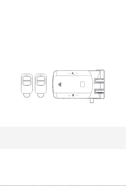
Major Parts
ON
OFF
ON
OFF

The device packed with 3M double-side stickers, can easily stick the Wireless Keypad and
Wireless Lock on smooth surface (We used high-quality 3M stickers, the stickiness will be the
best after sticking in 24 hours).
Below introduction for how to installWireless Lock intensively:
Method 1: Stick by 3M stickers
Confirm the direction and position of Hasp, meanwhile, make sure the Hasp align the
doorframe.
(So please make sure the direction of Hasp is fit for main body of lock before installation.)
Attentions of installing the Hasp
Put the Locating Rings into Hasp, and stick the 3M sticker at the back side of Hasp (You can
screw the hasp on the Reinforcing Plate if needed, then stick 3M sticker at the back of plate. It
can increase the stick area to make the Hasp stronger).
Installing the Hasp
Fix the main body of lock and the Fixed Plate by M5*6 hex screws in the packaging, and stick the
3M sticker on the back of Fixed Plate.
Installing the main body of lock
OPEN
CLOSE
INTRODUCTION

Press the Mechanical Switch on the main body of lock to open the lock mechanically, and
match the Hasp. Make sure it can be combined with Hasp perfectly, then stick the mail body of
lock on the door.
Combining the lock
Note: Mechanical Switch, it is used for installation and equipment trouble, please don’t
press it often in the normal condition.
When press the Mechanical Switch, the lock will be unlock all the time until open the
door one time by valid card, or valid PIN, or touch the close icon on the lock, or unlock
button on Remote Transmitter.
Method 2: Install by screws
OPEN
CLOSE
OPEN
CLOSE
87mm
61mm

Simplified Instruction
Function description
Enter the Program Mode:
Change the Master Code:
IMPORTANT NOTE: Please remember
the New Master Code as it can’t be reset
to default if forgotten
Add PIN User:
Add Card User:
Add fingerprint User:
Delete User:
Exit from the Program Mode:
How to release the door
PIN Access:
Card Access:
By Remote Transmitter:
By Wireless Lock:
Lock Immediately
By Keypad:
By Remote Transmitter:
By Wireless Lock:
Fingerprint Access:
Enter and Exit Program Mode
Operation
*(123456)#
(123456 is the factory default master code)
0 (New Code) # (Repeat New Code) #
(code: 6 digits)
1 (User ID) # (PIN) #(Repeat PIN) #
1 (Read Card)
1 (User ID) #(Read fingerprint)
#(Repeat Read fingerprint) #
2 (User ID) #
2 (Read Card)
*
PIN #
(Read Card)
Press
Touch
Press“0#”
Press
Touch
(Read Fingerprint)
Programming Step Keystroke Combination
1. Enter Program Mode
2. Exit
* (Master Code) #
(Factory default is 123456)
*
OPEN
CLOSE
PROGRAMMING

Set Master Code
Programming Step Keystroke Combination
1. Enter Program Mode
2. Update Master Code
3. Exit
Please do remember your Master Code because the Master Code can’t be reset if forget it.
* (Master Code) #
0(New Master Code)#
(Repeat New Master Code)#
Master code is any 6 digits
*
Add Users PIN(s)
Programming Step Keystroke Combination
1. Enter Program Mode
2. Add PIN
3. Exit
User ID: 0~499
PIN length: 4~8 digits
* (Master Code) #
1 (User ID) # (PIN) # (Repeat PIN) #
The users can be added continuously
*
Add Users Card(s)
Programming Step Keystroke Combination
1. Enter Program Mode:
2. Add Card:
Using Auto ID(Allows to assign Card
tonext available User ID number)
OR
2. Add Card:
Select Specific ID(Allows Master to
define a Specific User ID to associate
the card)
3. Exit:
User ID: 0~499
Card type: 13.56MHz M1 Card
* (Master Code) #
1 (Read Card) #
The cards can be added continuously.
1(User ID) # (Read Card) #
*
Change PIN
Programming Step Keystroke Combination
1.Change PIN:
By Card(There will be auto allocate
PIN (8888) to cards when adding)
OR
Change PIN: By User ID
2. Exit:
Note: Below is done outside programming mode, users can undertake this themselves
* (Read Card) (Old PIN) # (New PIN) #
(Repeat New PIN) #
* (User ID) # (Old PIN) # (New PIN) #
(Repeat New PIN) #
Exit automatically

Set Safety Mode
In safety mode, it can be set to deny access for 10 minutes after 10 failed PIN/card attempts in
10 minutes
(Factory default is OFF).
Delete Users
Programming Step Keystroke Combination
1. Enter Program Mode:
2.Delete user:
OR
Delete Card:
OR
Delete all users:
3. Exit:
* (Master Code) #
2 (User ID) #
The users can be deleted continuously.
2 (Read Card) #
2 (Master Code) #
*
Set Access Mode
Programming Step Keystroke Combination
1. Enter Program Mode:
2. Ad2. PIN Access:
OR
PIN + Card Access:
OR
PIN or Card:
3. Exit:
* (Master Code) #
3 0 #
3 1 #
3 2 # (factory default)
*
Programming Step Keystroke Combination
1. Enter Program Mode:
2. Strike-Out OFF:
OR
Strike-Out ON:
3. Exit:
* (Master Code) #
6 0 # (factory default)
6 1 #
*
Set Buzzer
Programming Step Keystroke Combination
1. Enter Program Mode
2. Buzzer OFF
OR
Buzzer ON
3. Exit
* (Master Code) #
7 0 #
7 1 # (factory default)
*

OTHERS
Users Operation
Programming Step Keystroke Combination
PIN User Access:
Card User Access:
Fingerprint Access:
PIN + Card User Access:
By Remote Transmitter:
(PIN) #
(Read Card)
(Read Fingerprint)
(Read Card) (PIN) #
Press
How to Open & Close the lock when the user is inside the door?
Programming Step Keystroke Combination
Open the lock:
Close the lock:
By Remote Transmitter:
Touch on the lock
Touch on the lock
Press
OPEN
CLOSE
The Wireless Lock will be locked automatically around 5 seconds after we open it. If we want to
lock it faster, please press“0 #”on the Keypad, or press on the Remote Transmitter, or touch
on the wireless lock, it will lock immediately.
Lock Immediately
(They are already paired when out of factory, if no problem, the users do not need to do this
operation in using.)
Pair Wireless Keypad / RemoteTransmitter withWireless Lock
CLOSE
Note: 1. The Wireless Lock can pair 16 parts (Keypad + RemoteTransmitter) maximum.
2. When pairing, all parts must be paired, then exit paring mode. If need adding one more
part, you still need to pair all parts again.
Step 1: Enter pairing mode
Open the battery cover of Wireless Lock, press the small round button left of battery
with a slender rod, hold it for 2 seconds until hearing two beeps, that means in the
pairing status.
Step 2: Pairing Wireless Keypad
Press the button“0 #”on the keypad, hold it for 2 seconds until hearing two beeps from
Lock, that means pairing successfully.
Step 3: Pairing RemoteTransmitter
Press any button on the Remote Transmitter, hold it until hearing two beeps from Lock,
that means pairing successfully.
Step 4: Exit pairing mode
After pairing all parts, press the small round button in the Wireless Lock again, hold it
until hearing two beeps, that means exit pairing successfully.

Operation
Status
Device
Sound and Light Indication
Low battery
reminding
Standby
Enter into
program
mode
Shines
per 1.5
seconds
Unlock
the lock
Press key
Wrong
operation
Invalid
PIN/Card/
fing erprint
ON for 1
second
ON for 1
second
ON for 1
second
LED ON for
1 second
ON for 1
second
Keypad
(finger-
print)
Remote
Trans-
mitter
Exit from the
program
mode
Any key press low
battery icon turn
on 5’S then off
Low battery
reminding
Pairing ON
Unlock
the lock
Lock
Lock
Low battery
reminding
LED shining, and beeps
Press button
Red LED
(Note: The lock will open automatically when the battery is
too low or run out, please change the battery INTIME!)
-- --
--
--
--
--
--
--
--
--
--
--
--
--
--
--
--
--
--
--
--
--
--
--
--
--
--
--
--
--
--
ON for 3
seconds
Green
LED
Low battey
ICON
When the
LED is dim,
please change
the battery
Buzzer
One beep
One beep
One beep
One beep
One beep
Two beep
Three beeps
Three beeps
Three beeps
when press
any button
One long beep

Name
Packaging box
Wireless Lock
Remote Transmitters
Manual
Screw Driver
Wall Fixing Plus
Self Tapping Screws
Accessories ofWireless Lock
3M Stickers
Packing List
Quantity
1pc
1pc
2pcs
1pc
1pc
4pcs
4pcs
4sets
4pcs
Table of contents
Popular Lock manuals by other brands

Simons Voss Technologies
Simons Voss Technologies LockNode MP Z4 quick guide

Chubbsafes
Chubbsafes Primus Quick user guide

Hafele
Hafele ER5000 installation guide

Comunello
Comunello AF 550 instruction manual

M&C
M&C Padlock user manual

schmersal
schmersal AZM300Z-I2-ST-1P2P-N-DU Operation and assembly instructions


