8
6. Troubleshooting
ERROR
CODE FAULT ACTION
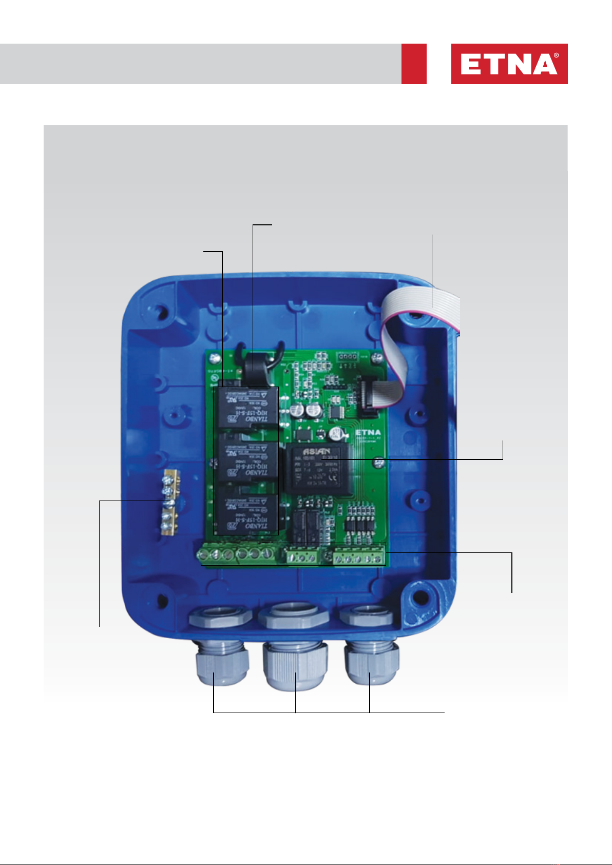
htA YG HIGH
VOLTAGE
FAULT
• Check the mains input voltage, phase-neutral values for all phases.
• When the high voltage protection value defined with "YG" is exceeded, this error is
given. Check the "YG" value.
• Check the mains voltage, cable and terminal connections.
htA dG LOW
VOLTAGE
FAULT
• Check the mains input voltage, phase-neutral values for all phases.
• When it goes below the low voltage protection value defined with “dG”, this error is
given. Check the “dG” value.
• Check the mains voltage, cable and terminal connections.
htA FS PHASE
SEQUENCE
FAULT
• When the phase sequence is reverse, the phase sequence error code “htA FS” is written
on the screen and the system does not work. Change the phase sequence from the
input and make sure that the motor rotates in the correct direction.
htA FY PHASE
LOSS FAULT
• One or more of the phases do not come to the energy supply terminals.
• Check the mains input voltage, phase-neutral values for all phases.
• Check whether there is any imbalance or phase loss between phases.
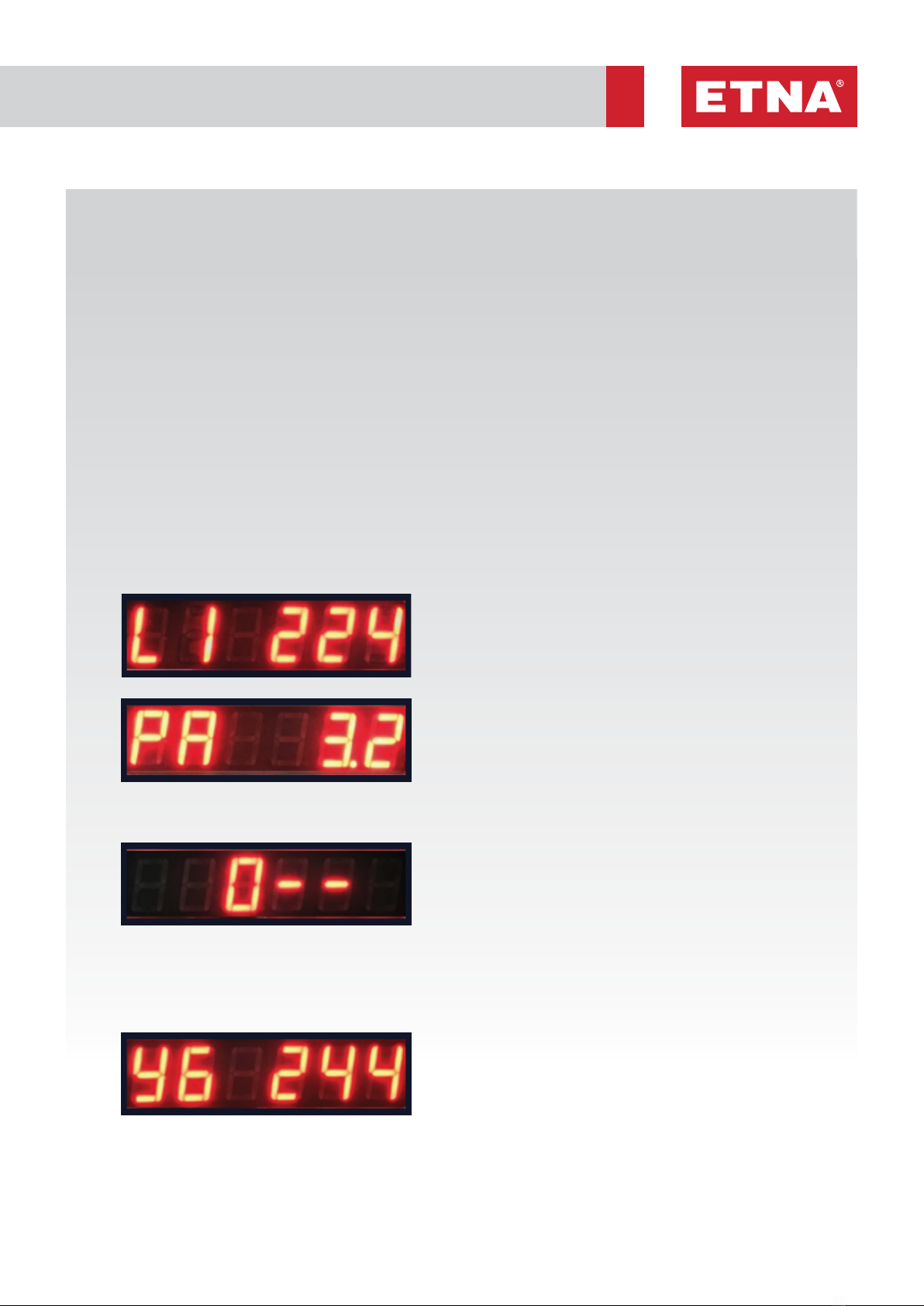
htA YA HIGH
CURRENT
FAULT
• Before taking the measurement, make sure that there is no mechanical failure in the
pump.
• Test the current drawn by the motor, measure it with the help of an ammeter and
compare it with the value indicated on the motor nameplate.
• Compare the "High Current Protection" value adjusted with the "YA" parameter with the
value specified on the motor nameplate.
• Check the motor cable and terminal connections.
• Verify that the overcurrent protection value (YA) is 10% above the maximum operating
current of the pump at full load and that the pump operates properly.
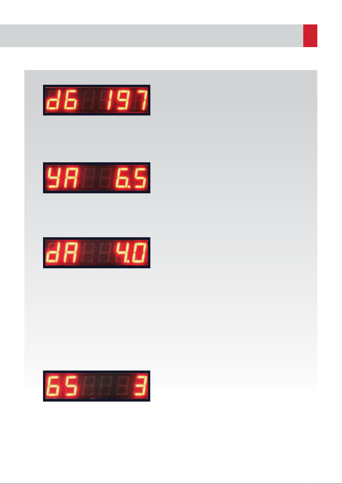
htA dA LOW
CURRENT
FAULT
• Before taking the defined measurements, make sure that there is no mechanical failure
in the pump and that the motor pump group works properly.
• Make sure that the pump suction and discharge valves are not closed.
• Make sure there is water in the reservoir.
• Make sure that there is no air in the system. If there is air, evacuate the air.
• Check the "Low Current Protection" value adjusted with the "dA" parameter.
• While the engine is running, close the suction valve and see how far the current has
dropped and note it. Make sure that the mains voltage is between 380-400 V during the
measurement.
• Defined Low Current Protection value must be 10% higher than this measured value.
After the low current limit is adjusted, make sure that the pump has low current error by
closing the suction valve during operation.
• When the tests are completed, open the suction valve again to confirm that the pump
works correctly.
htA SY NO WATER • Make sure that there is water in the tank.
• Make sure that the float switch (floater) level is adjusted properly.
• Make sure that the float switch works correctly by checking the float switch cable and
terminal connections.
htA th OVERFLOW
FAULT
• This error is given when the "CS" parameter is "1", that is in the discharge mode, if the
“SALTER (switch)” terminals are short-circuited.
• Check the overflow float switch cable and terminal connections and make sure that it
works properly.
• Check whether there is overflow.
htA bL BLOCKAGE
FAULT
• The system is blocked because a low current error has occurred and the low current
error continues even after software-defined automatic reset attempts.
• Repeat the checks in the “htA dA” part.
• Reset the error manually by holding down the Up / Down buttons and make sure that
the system works correctly.