ETNA Hydropan User manual

Hydropan Single with Alarm Kit
Operation and Maintenance Manual

2
1. Product Information
Hydropan-Single Control Panel is used to control , display modes and faults of single
pump booster systems, has 7 segment display and uniquely designed electronic main
board. In addition to the electronic board and 7 segment display, the panel also has No
Water / Pressure Switch / Fault warning leds as well as Up / Down buttons used to surf
in menus , Approval button to confirm parameter changes and ON / OFF button . System
parameters can be set easily by using Up / Down / Approval buttons located on the front
casing.
Panel On / OFF
Button
Parameter Set
Confirmation and
Menu Entrance
Button
Waterless Run
Warning Led 7 Segment
Display
Menu Surf and
Parameter
Setting Buttons
Pressure Switch
Signal Warning
Led
General Fault
Warning Led
Figure 1. Hydropan- Single External View

3www.etna.com.tr
Connectors
Cable Glands
Voltage
Transformer
7 Segment Display
Connection Cable
Current Transformers
Power Relays
Earth
Connection Bar
Figure 2. Hydropan Single Internal View

4
2. Technical Specifications
• Compatible with booster, deep well and waste water applications
• User friendly interface
• 8 bit microcontroller based design tabanlı tasarım
• 7 Segment display
• 3 phase voltage measurement and display on screen
• High Voltage Protection Setting
• Low Voltage Protection Setting
• High Current Protection Setting
• Current and Voltage fault delay time setting
• General Fault/ Dry Running and Pressure Switch signal warning leds
• Pump running currents display on screen during operation
• Ability to Reset faults
• Dry running protection with floater
• Additional dry running protection using minimum current protection algorithm
• Display all faults on screen
• Audible fault warning with buzzer
Figure 3. Panel Dimensions
Length: 170 mm
Width: 75 mm
Height: 195 mm
Weight: 775 gr

5www.etna.com.tr
3. Leds and Buttons on Front Panel
• General Fault Led: This led is ON together with written fault code on 7 segment display
when low current, high current, low voltage and high voltage protections are active.
• Up / Down Buttons: These buttons enable to surf within menus on 7 segment display and
they are used to set values of numerical parameters. In addition to this, the fault occured on
the system can be reset whşle pressing these buttons together for 5 seconds.
• Approval Button: This button enables to enter submenus and save the parameter already
set values.
• Switch Led: This led is ON when the pressure switch on the system is active.
• ON/OFF Button: This button is used to start-up and switch-o the panel OFF is written on 7
segment display when the panel is switched-o and there is power supply on the system.
Voltage value between L1-L2-L3 and neutral is
displayed in sequence as seen on the right hand
side when there is no signal from pressure switch.
In case there is signal from pressure switch and
system starts operating, pump current is displayed.
When display is on main screen and “Approval”
button is pressed, High Voltage Protection Setting
Menu is displayed. It is possible to enter the
submenu by re-pressing the “Approval” button and
high voltage protection value can be set by using
“Up/Down” buttons
Low Voltage Protection Setting Menu can be
reached by pressing “Approval” button first and
then “Down” button for once when display is on
main screen. It is possible to enter the submenu by
re-pressing the “Approval” button and low voltage
protection value can be set by using “Up/Down”
buttons.
4. Menus
a. High Voltage Protection Setting Menu
b. Low Voltage Protection Setting Menu
Figure 4. Panel Main Operating Screen
Figure 5. High Voltage Setting Menu
Figure 6. Low Voltage Setting Menu

6
High Current Protection Setting Menu can be
reached by pressing “Approval” button first and
then “Down” button for two times when display is
on main screen. It is possible to enter the submenu
by re-pressing the “Approval” button and high
current protection value can be set by using “Up/
Down” buttons
Low Current Protection Setting Menu can be
reached by pressing “Approval” button first and
then “Down” button for three times when display is
on main screen. It is possible to enter the submenu
by re-pressing the “Approval” button and low
current protection value can be set by using “Up/
Down” buttons
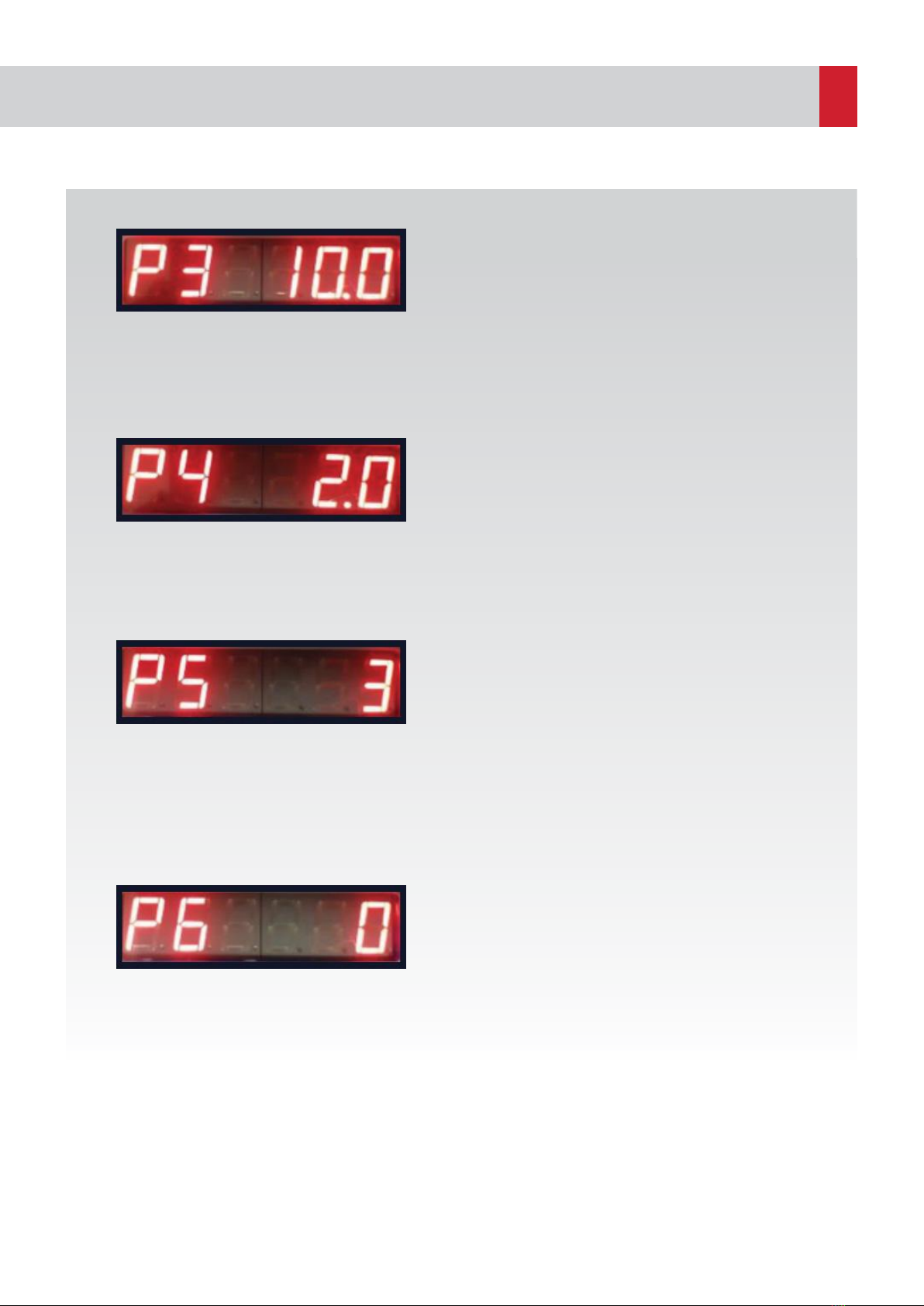
Fault display delay duration means when a
fault detected on the system , warning will be
delayed for this parameter long. Fault Display
Delay Duration Menu can be reached by pressing
“Approval” button first and then “Down” button
for four times when display is on main screen. It is
possible to enter the submenu by re-pressing the
“Approval” button and fault display delay duration
value can be set by using “Up/Down” buttons
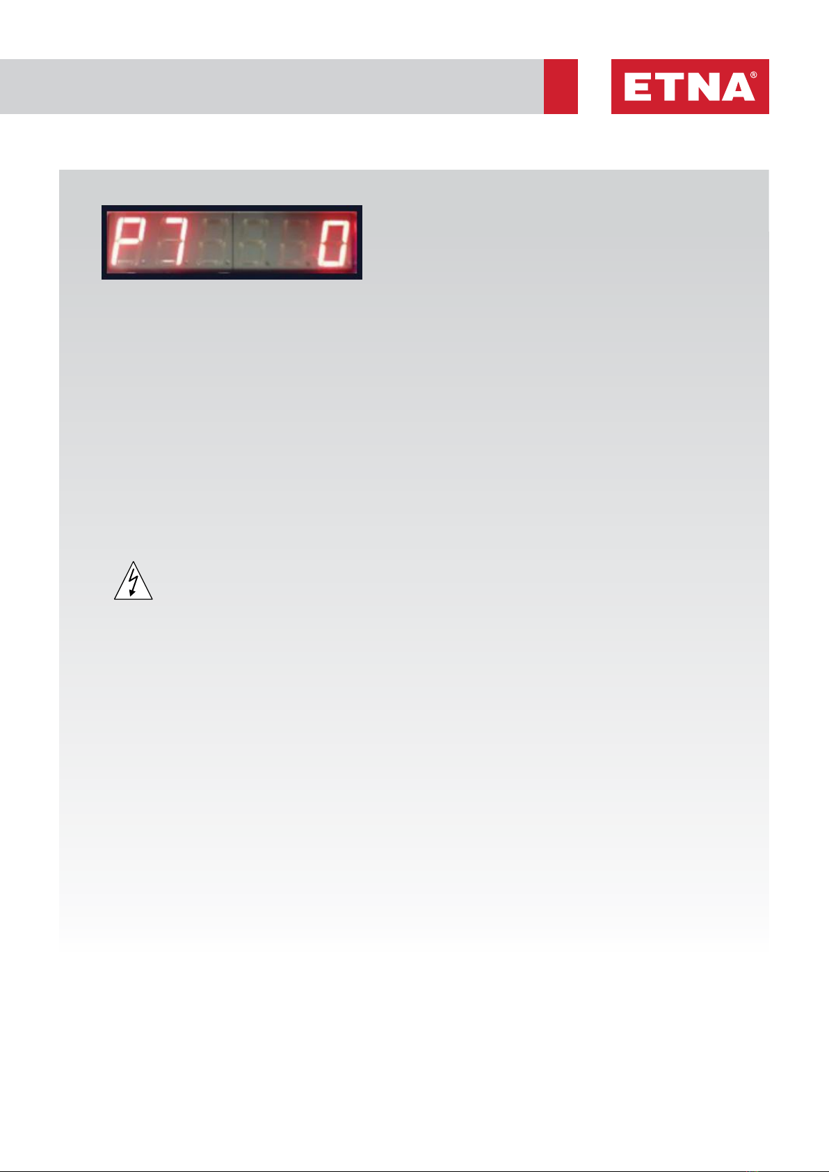
Pump Operation Mode Selection Menu as P6
seen on the Figure 10 can be reached by pressing
“Approval” button first and then “Down” button
for five times when display is on main screen. It is
possible to enter the submenu by re-pressing the
“Approval” button and pump operation mode can
be set by using “Up/Down” buttons. By setting the
parameter to “0” the panel can be used in booster,
waste water and deep well applications. When
parameter is set to “1” panel can be used in well
discharging applications. When parameter is set
to “2” panel can be used in well and water storage
tank filling applications.
Figure 7. High Current Settings Menu Menu
Figure 9. Fault Display Delay Duration Menu
Figure 10. Pump Operation Mode Menu
Figure 8.Low Current Settings Menu
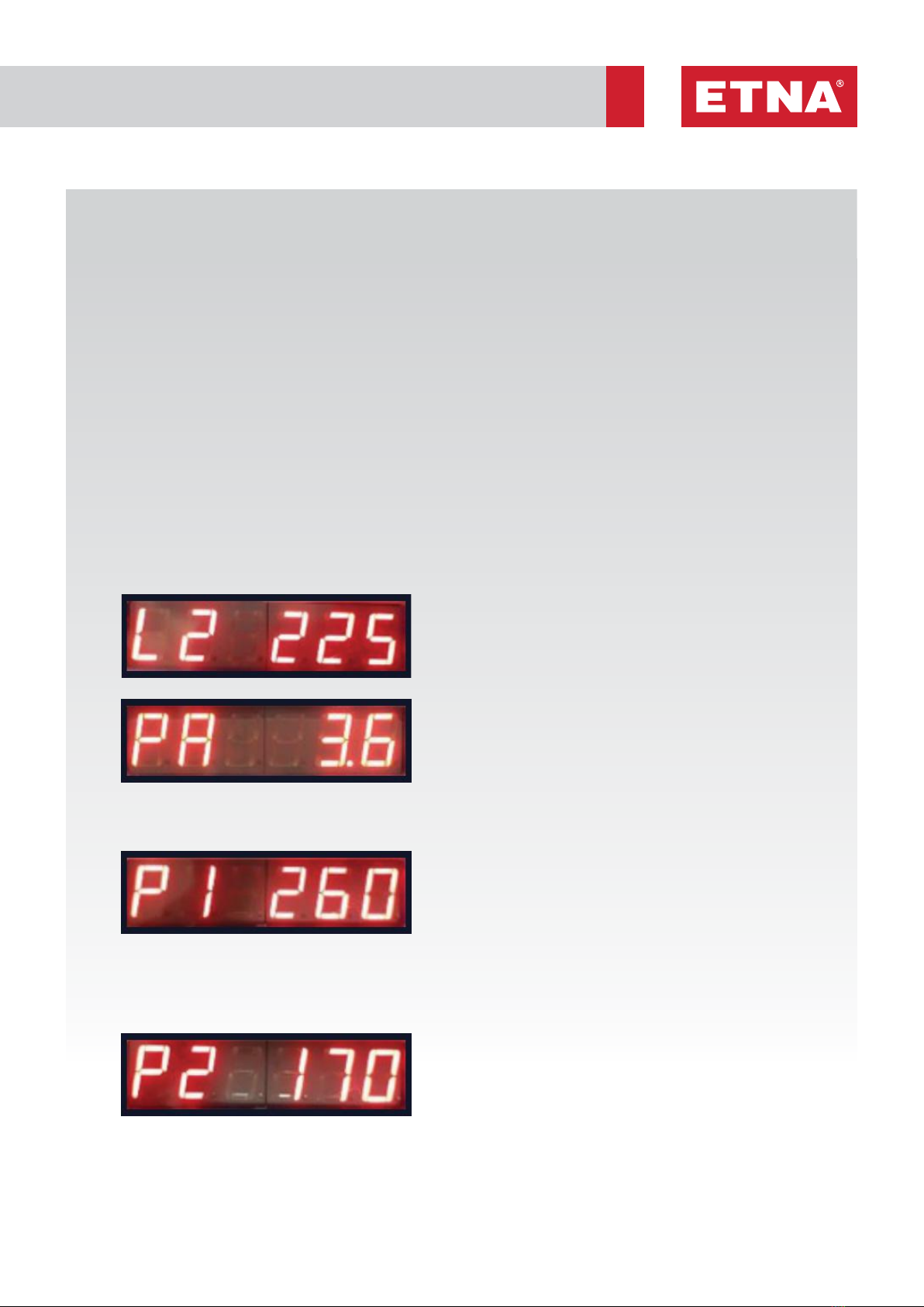
c. High Current Protection Setting Menu
d. Low Current Protection Setting Menu
e. Fault Display Delay Duration Menu
f. Pump Operation Mode Selection Menu

7www.etna.com.tr
Well Filling / Discharging Duration Setting Menu
can be reached by pressing “Approval” button
first and then “Down” button for six times when
display is on main screen. It is possible to enter
the submenu by re-pressing the “Approval”
button and well filling / discharging duration value
can be set by using “Up/Down” buttons. This
parameter becomes active when Pump Operation
Mode parameter set to “1” or “2” , requested time
duration for well filling or discharging can be set in
minutes. If this parameter is set to “0” it becomes
out-of-use.
Figure 11. Well Filling / Discharging
Duration Menu
g. Well Filling / Discharging Duration
Setting Menu
5. Maintenance
Please cut the power supply before performing any intervention.
• Check and make sure that there is no loose connections on power supply and earth
connection
• Check and make sure that there is no damage , hole or color change caused by
overheating on cables.

8
ERROR CODE FAULT ACTION
ERROR 1 HIGH
VOLTAGE
FAULT
• Check power supply input value
• Check high voltage protection value as parameter P1
ERROR 2 LOW
VOLTAGE
FAULT
• Check power supply input value
• Check low voltage protection value as parameter P2
• Check power supply cable and connector connections
ERROR 3 PHASE
SEQUENCE
FAULT
• Error 3 is occured on 7 segment display in case phase sequence fault
and system does not work. Change the sequence of phases on power
supply input.
ERROR 4 HIGH
CURRENT
FAULT
• Before performing any measurement, make sure there is no mechanical
congestion in pump
• Measure the current and compare with motor nominal current value
printed on motor label.
• Check high current value set in the parameter P3 and compare with
motor nominal current value printed on motor label
• Check motor cable and connector connections.
ERROR 5 LOW
CURRENT
FAULT
• Before performing any measurement, make sure there is no mechanical
congestion in pump
• Make sure that pump suction valve is not closed.
• Make sure the pump is deaerate before operation.
• Check low current protection value parameter P4
• Measure the current value when suction valve is closed and motor in
operation. Be careful the input voltage is between 380-400 V during this
measurement.
• The set parameter of low current protection must be %10 higher than
measured value
ERROR 6 NO WATER • Make sure there is enough water in storage tank.
• Make sure floater level is adjusted properly
• Check floater cable and contactor connections
ERROR 7 BLOCKAGE
FAULT
• System is blocked when low current protection algorithm completed and
there is still low current alarm.
• Make sure that pump suction valve is not closed
• Make sure the pump is deaerate before operation
• Check floater in water storage tank
6. Troubleshooting

9www.etna.com.tr
30A Relay
U V W
MOTOR
POWER
POWER
INPUT
FLOATER
PRESSURE
SWITCH
COM
RUN
FAULT
L1 L2 L3
Pe
30A Relay TRANSFORMER
HYDROPAN 1
30A Relay
TR
30A Relay
U N
MOTOR
POWER
POWER
SUPPLY
FLOATER
PRESSURE
SWITCH
COM
RUN
FAULT
N L1
Pe
30A Relay TRANSFORMER
HYDROPAN 1
30A Relay
TR
U N
MOTOR
POWER
POWER
SUPPLY
N L1
30A Relay
U V W
MOTOR
POWER
POWER
INPUT
PRESSURE
SWITCH
COM
RUN
FAULT
WELL
L1 L2 L3
Pe
30A Relay TRANSFORMER
HYDROPAN 1
30A Relay
TR
30A Relay
PRESSURE
SWITCH
COM
RUN
FAULT
WELL
Pe
30A Relay TRANSFORMER
HYDROPAN 1
30A Relay
TR
Figure 13. THREE PHASE
Deep Well Mode Connection
Figure 15. SINGLE PHASE
Deep Well Mode Connection
Figure 12. THREE PHASE
Booster Mode Connection
Figure 14. SINGLE PHASE
Booster Mode Connection

Dudullu Organize Sanayi Bölgesi 2. Cadde No: 14
34775 Ümraniye İstanbul / Turkey
Tel : +90 216 561 47 74 (Pbx) • Fax : +90 216 561 47 50
www.etna.com.tr/en • inf[email protected] customer service
Other manuals for Hydropan
2
Table of contents
Other ETNA Control Panel manuals
Popular Control Panel manuals by other brands

Bosch
Bosch REXROTH IndraControl VAM 42.1 Project planning manual

technoswitch
technoswitch TEC601 Installation & operation manual

Divus
Divus Touchzone Series user manual

Controls
Controls MVP-A3413-FT4 product manual

Belden
Belden Grass Valley Kayenne Installation & service manual

GFA
GFA TS 971 Series installation instructions

Garmin
Garmin GPSMAP 12 3 Series owner's manual

Arrowhead Alarm Products
Arrowhead Alarm Products ELITE SX-2 Installation & programming guide

NEC
NEC Attendant Xen IPK Attendant user guide

HEIDENHAIN
HEIDENHAIN POSITIP 8000 operating instructions

Piusi
Piusi MC BOX Use and maintenance manual

Fagor
Fagor Innova 40i Installation and operation manual