Etnyre Black-Topper Centennial Distributor User guide

E.D. ETNYRE & CO. – 1333 S. Daysville Road – Oregon, Illinois 61061
Phone: 815-732-2116 or 800-995-2116 – Fax: 800-521-1107 – www.etnyre.com
Version 3.9.4
Black-Topper®CENTENNIAL
Asphalt Distributor
With BT 1 Controls
M-114-10
Serial Number S3985 thru S5315
with BT1 Controls
For Units with Variable Width Spray Bar

1
M-114-10
Black-Topper Centennial Operation, Maintenance, and Safety Manual
BLACK-TOPPER Distributor with
Variable Width Spraybar and BT-1 Controls
Serial Number S3985 thru S5315
WARRANTY
E. D. Etnyre & Co. warrants to the original Purchaser, it’s new product to be free from defects in material and
workmanship for a period of twelve (12) months after date of delivery to original Purchaser. The obligation of the
Company is limited to repairing or replacing any defective part returned to the Company and will not be responsible for
consequential damages or any further loss by reason of such defect.
The company excludes all implied warranties of merchantability and fitness for a particular purpose. There are no
warranties, express or implied, which extend beyond the description of the goods contained in this contract.
This warranty does not obligate the Company to bear the cost of machine transportation in connection with the
replacementorrepairofdefectiveparts,nordoesitguaranteerepairorreplacementofanypartsonwhichunauthorized
repairs or alterations have been made or for components not manufactured by the Company except to the extent of
the warranty given by the original Manufacturer.
This warranty does not apply to:
(1) Normal startup services, normal maintenance services or adjustments usually performed by the selling dealer,
factory service representative or customer personnel.
(2) Any product manufactured by E. D. Etnyre & Co. purchased or subjected to rental use.
(3) Any product or part thereof which shows improper operation, improper maintenance, abuse, neglect, damage or
modification after shipment from factory.
(4)Anyproduct or part thereof damaged or lostinshipment. Inspection for damage should be made beforeacceptance
or signing any delivery documents releasing responsibility of the delivering carrier.
This warranty and foregoing obligations are in lieu of all other obligations and liabilities including negligence and all
warranties of merchantability or otherwise, express or implied in fact or by law.
WARNING
Do not use this machine for any operation that is
not described in this manual.
If you have any questions about operation of this
machine, contact the Etnyre Service Department
at 1-800-995-2116 or 1-815-732-2116.
Operations that are not approved could cause
serious injury or death.
WARNING
Diesel engine exhaust and some of its constituents
are known to the State of California to cause
cancer, birth defects, and other reproductive harm.
Please note this warning
and remember:
• Always start and operate the engine in a well
ventilated area.
• If in an enclosed area, vent the exhaust to the
outside.
• Do not modify or tamper with the exhaust system.
Can cause serious injury or death.
Version 3.9.4

2
© Copyright 2008 E.D. Etnyre & Co.
All brand names, trademarks and registered
trademarks are the property of their respective
owners. Information contained within this
document is subject to change without notice. All
rights reserved.

3
Table of Contents
Safety Instructions
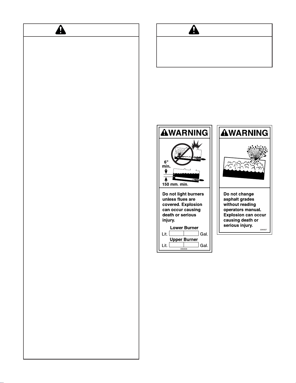
Warning And Instruction Plates......................... 5
General Safety Instructions .............................. 7
Safety Precautions, Hazard Seriousness Level 7
WARNINGS ...................................................... 8
Fluoroelastomer Handling.............................. 8
Foaming .......................................................... 10
Asphalt Institute .............................................. 10
Introduction ................................................... 11
Reporting Safety Defects................................ 11
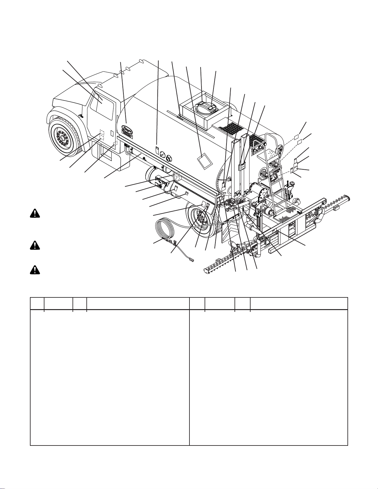
Component Location And Identification .......... 12
Rear and Side Components............................ 12
Spray Bar Components................................... 13
Hydraulic Tank Components ........................... 13
Cab Control Panel........................................... 14
Rear Control Panel ......................................... 17
Preparing for Operation ............................... 19
Setting Up the Computer ................................ 19
First Screen..................................................... 19
Second Screen ............................................... 19
Third Screen ................................................... 19
Fourth Screen ................................................. 20
Fifth Screen..................................................... 20
Sixth Screen.................................................... 20
Seventh Screen .............................................. 20
Eighth Screen ................................................. 20
Engaging Pump on PTO Equipped Distributors .... 21
Manual Transmissions .................................... 21
Automatic Transmissions ................................ 21
Spraying Operations ....................................... 22
Setting the Digital Memory Presets ................ 23
Adjusting the Spray Bar Nozzle Angle ............ 23
Adjusting the Spray Bar Height....................... 23
Operation ....................................................... 25
Tank Capacity ................................................. 25
Operation Screens .......................................... 25
First Operating Screen.................................... 25
Second Operating Screen............................... 25
Third Operating Screen................................... 26
Information Messages..................................... 26
Loading ........................................................... 28
Loading Through the Manhole........................ 28
Loading Through the Load Line Connections
and Preliminary Checks .................................. 29
Check Strainers .............................................. 29
Using the Measuring Stick .............................. 29
Loading Through the Load Line...................... 29
Circulating in the Tank..................................... 31
Circulating Product in the Bar ......................... 33
Spraying (Auto) ............................................... 35
Hand Spraying ................................................ 36
Bar Suck Back Override.................................. 37
Spray Bar Suckback ....................................... 38
Flushing Operations........................................ 40
Bar Flush (Auto).............................................. 40
Bar Flush (Manual) ......................................... 41
Unload Operations with External Pump.......... 42
Unload Operations with Distributor Pump....... 44
Transfer Operations ........................................ 46
Heating Product in Distributors .................. 48
Heating with Liquid Propane Gas (LPG) Burners .. 48
LPG Supply Tank Requirements..................... 48
Manual Control Burners .................................. 49
Burner Operation ............................................ 49
Burners With Outfire Controls......................... 50
Burners with Automatic Ignition and
Temperature Limiting Control........................ 53
Burner Operation with Auto Ignition &
Temperature Control ..................................... 53
Electric Driven Burner Diesel Operation ......... 54
Troubleshooting............................................ 55
Maintenance .................................................. 57
Electrode Assembly Adjustments.................... 57
Burner Air Band Settings................................. 57
Check Ignition Transformer Spark .................. 58
Fire Burners .................................................... 58
Replacing Speed Pickup................................. 58
Servicing the Etnyre P-15 Pump..................... 59
Vacuum Check................................................ 59
Impeller Installation And Pump ....................... 59
General Fuel Data and Heating Terminology.. 60
Fuel Data ........................................................ 60
Approximate Burner Fuel Consumption.......... 60
Heating Terminology ....................................... 60
Hydraulic Fluid Requirements......................... 61
General Information ........................................ 61
Hydraulic Fluid Requirements......................... 61
Viscosity & Temperature Requirements.......... 61
Contamination Levels ..................................... 62
Lubrication Chart............................................. 64
Etnyre Spraybar Nozzles ................................ 65
Decimal Equivalent Chart ............................... 66

4
List of Illustrations
Figure 1. Location of Warning and Instruction Plates.................................... 5
Figure 2. Rear and Side Component Identification...................................... 12
Figure 3. Rear Component Identification..................................................... 12
Figure 5. Hydraulic Tank Component Identification. .................................... 13
Figure 4. Spray Bar Component Identification............................................. 13
Figure 6. Cab Control Panel Components................................................... 14
Figure 7. Rear Control Panel Components.................................................. 17
Preparing for Operation
Figure 8. Adjusting the Spray Bar Nozzles. ................................................. 23
Figure 9. Adjusting the Spray Bar Height..................................................... 23
Operation
Figure 11. Valve Positions for Loading Through the Manhole. .................... 28
Figure 12. Using the Measuring Stick.......................................................... 29
Figure 13 Valve Positions for Loading Through the Load Line.................... 30
Figure 14. Valve Positions for Circulating in the Tank. ................................ 31
Figure 15. Valve Positions for Circulating in the Bar.................................... 33
Figure 16. Valve Positions for Spraying Through the Bar............................ 35
Figure 17. Valve Positions for Handspray.................................................... 36
Figure 18. Valve Positions for Spray Bar Suck Back................................... 38
Figure 19. Valve Positions for Flushing. ...................................................... 40
Figure 20. Valve Positions for Unload with External Pump. ........................ 42
Figure 21. Valve Positions for Unload withDistributor Pump. ...................... 44
Figure 22. Valve Positions for Transfer. ....................................................... 46
Figure 23. Manual Control Burner System. ................................................. 49
Figure 24. Outfire Controlled Burner System. ............................................. 51
Figure 25. Burner System with Auto Ignition and Temperature Control. ..... 53
Figure 26. Electric Burner System. .............................................................. 54
Maintenance
Figure 27. Burner Electrode Adjustments. ................................................... 57
Figure 28. Electrode Assembly Installation.................................................. 57
Figure 29. Nozzle Adjustment...................................................................... 57
Figure 30. Hydraulic Motor........................................................................... 58
Figure 31. Etnyre Asphalt Pump. ................................................................. 59
Figure 32. Fluid Cleanliness Chart. ............................................................. 62
Figure 33. Serial Number Plate Location..................................................... 66

5
20
1
2
45
5
5
678
910
11
12
13
14
15
16 17
18
18 19
20
21
22
23
24
25
26
27
28
29
30
31
32 33
34
35
16320807 1 Decal-Warn, Master Power
26320808 1 Decal-Warn, Electrical Equipment
43390696 2 Decal, Blacktopper Centennial
56320797 3 Plate- Caution, Hot Surface
63390645 1 Label-Measuring Stick, 1 Flue
3390656 1 Label-Measuring Stick, 2 Flues
76320272 AR Placard System (Optional)
86320794 2 Plate- Warning, Manhole
96320790 1 Decal-Warning, GVWR
10 6320791 1 Decal-Handspray Operation
11 3390562 1 Bracket- Mtg, Decal, Hot Surface
12 6320800 1 Decal-Diesel Fuel Only
13 6320809 1 Decal-Instr, Air Oiler
14 6320784 1 Decal-Warning, Personal Protection
15 6320802 1 Decal-Warning, Handspray Hose
16 6320799 1 Plate- Warning, Burner, General
17 6320787 AR Decal- Directions, LPG Burner
18 6320785 2 Decal-Warn, 1” Handspray Hose
6320806 2 Decal-Warn, 3/4” Handspray Hose
Warning And Instruction Plates
For operator safety and possible
liability protection, all Safety and
Instruction Plates should remain
in place and be legible.
Should a plate be removed, lost,
or become illegible, reorder and
replace immediately.
If plates become difficult to read
because of material coating the
surface, clean with solvent.
19 6320804 1 Decal-Warning, No Riders
20 6320803 1 Decal-Gate Valve
21 6320801 1 Decal-Gate Valve Close
22 6320795 1 Decal- Warning, Fill Line Cap
23 6320789 1 Decal- Warning, Asphalt Grades
24 3390636 1 Decal- Warning, Flues Covered
25 6320796 2 Decal- Warning, Before Starting
26 6320793 2 Plate- Warning, Manuals
27 6320788 1 Decal-Lubrication Chart
28 6320792 AR Decal- Directions, Fuel Oil Burners
29 6320798 1 Decal- Warning, Safety, General
30 6320805 1 Decal- All American
31 3390655 1 Plate- Name, Distributor S/N, Brass
32 2790530 1 Plate-Name, Spec, 178.345
33 6320786 1 Plate-Instr, Hydraulic Oil
34 6320796 1 Decal- Warning, Before Starting
35 6320793 1 Decal- Warning, Manuals
AR = As required
Ref Part No. Qty Description Ref Part No. Qty Description
Figure 1. Location of Warning and Instruction Plates.

6
NOTICE
The handling of Cationic Emulsions (CRS-2, CMS-2, CSS-1 and CSS) may
create an environment within the Asphalt Distributor that can be corrosive to
carbon steel and cast iron.
•Cationic Emulsions are widely used within the industry.
•Cationic Emulsion is manufactured with asphalt, water, emulsifiers and
hydrochloric acid. The chemistry of individual emulsions varies in asphalt
content and Ph levels.
•Tanks and spray mechanisms used with Cationic emulsions may experience
corrosion
•It is believed the chemistry of the emulsion - specifically the residual fumes
promote the corrosion
• Etnyre Distributors are compatible with Cationic Emulsions provided that
certain precautions are taken.
•Prior to placing a distributor in to service with Cationic Emulsion, it should be
loaded with an AC or MC type material to develop a protective coating.
• Periodic inspection of the tank and spray system should be preformed in the
normal course of operation.
• It is recommended that distributors used in Cationic service be flushed
periodically and at the end of the season with an AC, MC or cutback to
remove the corrosive materials and to provide a protective coating.
•Increasing the quantity of flushing material during daily suck back and
cleanout operations will also help to minimize corrosion damage.
•Dilution is the solution.
• Additional information can be acquired from your Emulsion supplier as well as
the Asphalt Institute or the Asphalt Emulsion Manufactures Association.
WARNING
Take extra care and follow recommended
procedures when alternating asphalt materials
especially when loading hot product, over 212
degrees Fahrenheit (100 degrees Celsius), on
to a tank and system previously in Emulsion
service.

7
Theoperationof abituminous distributornormallyrequires handlingofliquid productsat elevatedtemperature.
Also, these liquids may be of a volatile nature.Aheating system is supplied to raise or maintain the product
temperature, and these systems use highly combustible fuels.As with any type of construction equipment,
there are certain hazards associated with careless or improper operation.
Safety warnings have been provided to call attention to any potentially hazardous situation that may cause
property damage, personal injury or death to the operator or bystanders. These safety warnings will be
shown at various times throughout this manual, as they are applicable to the subject being presented.
These safety warnings are identified by the following warning symbols:
Safety Precautions, Hazard Seriousness Level
You will find safety information boxes throughout this manual. These boxes contain information alerting you
to situations or actions to avoid.
Signal words (DANGER, WARNING, and CAUTION) are used to identify levels of hazard seriousness.
Their selection is based on the likely consequence of human interaction with a hazard. Definitions of hazard
levels are as follows.
DANGER - Immediate hazards which will result in severe personal injury or death.
WARNING - Hazards or unsafe practices which could result in severe personal injury or death.
CAUTION - Hazards or unsafe practices which could result in minor personal injury or product or
property damage.
All of these warnings are listed below and they also appear throughout the manual. In addition to these, you
will find notes throughout the manual.
NOTE - A note provides general information that the operator should be aware of when performing an
operation.
General Safety Instructions
DANGER
To avoid an extreme fire hazard or explosion,
NEVER use gasoline as fuel in diesel or fuel
oil burners.
WARNING
A fully charged dry chemical type fire
extinguisher must be within easy reach
whenever the burners are operating or there
is an open flame near the Distributor. The
minimum capacity of the fire extinguisher
should be 10 pounds.
Please Note This Warning
and Remember:
• Always start and operate the engine in a
well ventilated area.
• If in an enclosed area, vent the exhaust to
the outside.
• Do not modify or tamper with the exhaust
system.

8
WARNING
A fully charged dry chemical type fire
extinguisher must be within easy reach
whenever the burners are operating or there
is an open flame near the Distributor. The
minimum capacity of the fire extinguisher
should be 10 pounds.
Fluoroelastomer Handling
Some O-rings and seals used in this vehicle
are made from fluoroelastomers, When used
under design conditions, fluoroelastomers do
not require special handling. However, when
fluoroelastomers are heated to temperatures
beyond their design temperature (around
600º Fahrenheit), decomposition may occur
with the formation of hydrofluoric acid.
Hydrofluoric acid can be extremely corrosive
to human tissue if not handled properly.
A degraded seal may appear as a charred or
black sticky mass, Do not touch either the
seal or the surrounding equipment without
wearing neoprene or PVC gloves if
degradation is suspected. Wash parts and
equipment with 10% lime water (calcium
hydroxide solution) to neutralize any
hydrofluoric acid.
If contact with the skin occurs, wash the
affected areas immediately with water. Then
rub a 2.5 calcium gluconate gel into the skin
until there is no further irritation, while
seeking prompt medical attention.
Note to Physicians: For advice or treatment
of HF burns, call the DuPont Medical
Emergency number, 1-800-441-3637.
To prevent an explosion or fire hazard:
• Position the unit broadside to the wind to
prevent volatile fumes from drifting toward
the burners.
• Do not operate the burners if the tank is
damaged or leaking.
• Ensure that the burners are extinguished
before removing any material from the tank
in any manner. Liquid petroleum (LP)
burners can support a flame for several
minutes after the fuel supply is turned off.
To prevent an explosion or fire hazard:
• Do not operate the burners when the vehicle
is unattended, when the vehicle is in
motion, or with the vehicle in a confined
area.
• When the burners go out, shut off the fuel
supply to both burners and allow the flues to
ventilate for at least 3 minutes before re-
lighting the burners.
• Do not heat the material beyond the
manufacturer’s recommended temperature.
• Keep burning cigarettes or other sources of
combustion away from manholes and
overflow vents.
• Keep area free of all sources of combustion
when spraying.
• Check the tank vent to insure that it is free
from obstruction before lighting the burners.
• Eliminate sparks from engine exhaust.
• Do not operate the burners with the
manhole open or open the manhole while
the burners are in operation.
• Flues must be covered by a minimum 6
inches of material (bitumen) when burners
are in operation.
To prevent possible hand or facial burns:
• Always light the inside burner first. Do not
reach across a lit burner to light or re-light the
inside burner. Shut off the outside burner
before lighting the inside burner.
To prevent possible burns:
• Always use a torch to light the burners.
Never attempt to light the burners using a
match or pocket lighter.
• Always wear insulated gloves when
handling spray bar sections or hoses.
• Always wear eye protection, face shield,
long sleeve shirt, insulated gloves, boots,
and long pants outside the boots when
working around the Distributor.
• Use extreme caution when using a torch to
heat the pump. Asphalt accumulated around
the pump may ignite when heating the
pump with a torch.
WARNINGS

9
WARNINGS
To prevent possible burns from leaking
material:
• Be sure all pipe, cap and hose connections
are secure before opening valves, or
beginning any operation.
To prevent possible burns from hot
asphalt spray:
• Do not stand, or allow anyone to stand,
where accidental opening of a valve may
cause contact with hot asphalt.
To prevent possible burns from foaming
or violent eruption:
• Do not load tank with material temperature
over 200ºF if water or condensation is
present in tank, or if emulsion was used in
the previous load.
• Do not heat material over 200 ºF if moisture
or emulsified material is present in tank.
To prevent burns from hot asphalt when
hand spraying:
• Hold the handspray gun in proper position
and watch for other people.
To prevent possible burns to operators or
bystanders, or possible equipment
damage:
• Do not start any operation if any control
settings are unknown.
To prevent severe injury from becoming
entangled in machinery:
• Stand clear of rotating drives.
To prevent possible injury:
• Always open the manhole cover slowly.
Pressure build up in the tank may cause
the cover to burst open.
To prevent possible fire hazards, burns or
falls:
• Keep the unit clean for safe operation.
To prevent possible burns from material
overflow:
• Allow sufficient space in the tank for
expansion of the material when heating
• Before removing the fill line cap, make
certain that the asphalt pump is turning and
the tank valve is closed.
WARNING
To prevent possible personal injury:
• Do not load the vehicle beyond the GAWR
or GVWR. The maximum load volume must
be calculated based on material density.
Allowing the burners to operate for a long period
oftime without circulatingcan damage the product
and create explosive fumes. If product cannot be
circulated after fifteen minutes of heating without
circulation,theburners should be extinguishedfor
20 - 30 minutes before re-lighting the burners.
Use the measuring stick as shown in Figure 9 in
the
UsingtheMeasuringStick
sectionto determine
the amount of product in the tank before lighting
burners. The minimum amounts shown on the
warning placard only apply if the tank is level.
Remember that the measuring stick is accurate
only when the tank is level. Ifthe tankis notlevel,
repositionthe Distributorto placethe tankin alevel
positionbeforetaking finalmeasurement.Youmust
have at least the amounts shown, with the tank
level, in order to safely light the lower burner and
upper burner respectively. Failure to have the
appropriate amount, accurately measured can
result in an explosion causing death or serious
injury.

10
Foaming
WARNING
To prevent possible burns from foaming
or violent eruption:
• Do not load tank with material temperature
over 200 ºF if water or condensation is
present in tank, or if emulsion was used in
the previous load.
• Do not heat material over 200 ºF if moisture
or emulsified material is present in tank.
If the Distributor is to be filled with hot bitumen,
proceed very cautiously. If there is any moisture in
the tank, or if an emulsion product was the last
load, foaming or eruption may occur.
Dow-Corning DC-200 may be used to prevent
foaming in Distributors, Transports, and
Maintenance Units.
Mix the contents of one can (16 oz.) with one (1)
gallon of diesel fuel or kerosene. Add one (1) oz.
of this diluted mixture to each 1000 gallons of
asphalt. The correct amount may be poured
through the manhole. This will assist in reducing
foaming, particularly if moisture is present or if an
emulsified asphalt was used in a previous load.
Iffoaming does notoccur at thestart of theloading
operation, but you suspect that there may be
moisturein the spraybaror circulating system,the
loadingoperation shouldbestoppedwhenthe tank
is no more than 25% full. The product should then
be circulated through the spray bar at a rate of 80
to 100 GPM before continuing the loading
operation.
Iffoaming does occur, continue circulatinguntil the
foaming stops, and then suck back the product in
the spray bar back into the tank before filling the
tank the rest of the way.
Asphalt Institute
To further increase awareness of the hazards
associated with the operation of a bituminous
distributor, and before beginning initial operation,
the operator should also receive instruction by an
authorizedEtnyre dealer,or Etnyrerepresentative.
The Centennial Distributor is designed to handle
a number of different products, such as ACs,
cutbacks & emulsions.
Knowledge of these liquid asphalts is required for
safeoperation oftheDistributor.Itiscritical toknow
which product can be loaded after the previous
product,and which productsreact with eachother.
TheAsphaltInstituteisasource ofasphalthandling
safety information.
Asphalt Institute
Research Park Drive
PO Box 140052
Lexington, KY 40512-4052
606-288-4960

11
Your Etnyre Blacktopper Centennial Distributor is
designed to give you many years of accurate,
dependable, and economic service. The following
instructionswillenable youtoreceive themaximum
performance from your Blacktopper Centennial
Distributor.
The Blacktopper Centennial Distributor’s controls
are designed for simple operation. They require a
minimum of training for proficient usage. The
exclusive Etnyre circulating system is designed
and built for handling all grades of bituminous
materials efficiently.
This manual is provided as a tool to aid personnel in
theoperation ofthe EtnyreBlacktopperCentennial
Distributor in a safe and efficient manner. As with
any type of construction equipment, there are
certain hazards associated with improper or
careless operation. The ability to read and
understand the instructions in this manual should
be a required qualification to become an operator.
There are also functions that require a certain
amount of physical strength to accomplish.
Personslacking therequired strengthmay notonly
place themselves in jeopardy, but also others in
the vicinity.
Thismanual covers standard featuresand options
for truck mounted units with computerized
controllers only. If your unit is equipped with Basic
Controls,please refertoOperation manualnumber
M-102-99 or later. If your unit incorporates custom
features, some of the information contained in this
manual may not apply. If you have any questions
regarding this manual or your unit, contact your
Etnyre dealer or the E. D. Etnyre Service
Department at 1-800-995-2116.
CAUTION
Unusually strong electromagnetic
interference could cause the electronic
controls on this equipment to temporarily
malfunction. Test the effect of two way radios
and similar equipment while operating in a
safe area.
Introduction
Reporting Safety Defects
If you believe that your vehicle has a defect which
couldcause acrash,or couldcause injuryordeath,
you should immediately inform the National
Highway Traffic Safety Administration (NHTSA) in
addition to notifying E. D. Etnyre & Co.
IfNHTSA receives similar complaints, itmay open
an investigation; and, if it finds that a safety defect
exists in a group of vehicles, it may order
a recall
and remedy campaign. However, NHTSA cannot
become involved in individual problems between
you, your dealer, or E. D. Etnyre & Co.
To contact NHTSA, you may either call the Auto
Safety Hotline toll free at 1-800-424-9393 (or 336-
0123 in the Washington, D.C. area) or write to
NHTSA, U.S. Department of Transportation,
Washington,DC, 20696.Youcan alsoobtain other
information about motor vehicle safety from the
hotline.

12
Component Location And Identification
Rear and Side Components
Figure 2. Rear and Side Component Identification.
Figure 3. Rear Component Identification.
20
Hand Spray Gun
Hydraulic Oil Tank
Hydraulic Oil Filters
LPG Tank
(may be on right or left side)
Fuel Oil Burner Fuel Tank
on right side frame when
applicable Hose Trough
Thermometer Well
Tool Box and
Rear Control Panel
Manhole & Platform
Tank Gauge
Exhaust Stacks
Ladder
Burners
Sample Valve
Air Oiler (in right side
tool box)
Suction Valve
Strainer/Valve Box
Asphalt Pump
Transfer Line
Fill Line
Fill Line Strainer
Spray Bar Lift Cylinder
8’ Telescopic bar
with Valves and Nozzles
Exhaust Stack Dampers
4 Way Valve
Rotary Actuator
Suction Screen
Optional Front Tank Valve
(not shown)
Rear Tank Valve
Asphalt Pump
Drive Motor
Left Spray Bar
Feed Tube
Right Spray Bar
Feed Tube
Asphalt Pump Gearbox
Asphalt Pump
Hand Spray Gun
Suck Back Valve
Strainer Box
Master Handspray Valve
Transfer Valve
Transfer Line
Transfer Line
Suck Back Valve
Return
Valve
Fill Line
Fill Line Strainer
Flush Valve
Hand Spray Valve

13
Spray Bar Components
Hydraulic Tank Components
Figure 4. Spray Bar Component Identification.
Figure 5. Hydraulic Tank Component Identification.
4
1
15
6
7
8
8
9
2
3
10
4
1. Hydraulic Filter
2. Mounting Bracket
3. Hydraulic Tank Assembly
4. Thermometer
5. Fill Cap
6. Breather
7. Hydraulic Oil Specifications Instruction Plate
8. Pipe Plug
9. Oil Eye Sight Plug
10. Thermo Switch
Left
Folding Wing
Right
Folding Wing
Left 8 Ft Section
Right 8 Ft Section
Left Bar Shift Cylinder
Right Bar Shift Cylinder
Breakaway
Swivel Joint
Breakaway
Swivel Joint
Nozzle
Spray Bar Hanger
Left Wing Tilt Switch
Spray Valve
Air Valves
Right Bar Feed Connection
Left Bar Feed Connection
Wing Fold Cylinder Wing Fold Cylinder
Lift Cylinder
Lift Cylinder

14
Figure 6. Cab Control Panel Components.
Cab Control Panel Descriptions
1. One Foot Switches
These switches activate a corresponding foot of
spray bar valves, there are three spray valves per
foot of spray bar. Switch and spray valve number-
ingstartsfrom thecenterof theDistributorand goes
outward in each direction. One Foot switches that
are on a wing, which is raised, do not add to the
displayed spray width even if they are turned ON.
The activated, switch ON, foot of spray bar will
come
on
when the SPRAY switch is turned ON.
Thecomputer will automaticallychange the pump-
ing rate as spray valves are turned on or off while
spraying to compensate for the number of feet
being sprayed.
On variable width spray bars the spray valves
associated with switch 1 are only in the center of
theDistributor whenthe spraybar isfullyextended.
From the fully retracted position, spray valves as-
sociatedwith switch 4are the firstto beturned ON,
with switch 4 ON, as the spray bar is extended.
One Foot switches that are in the retracted portion
of a variable width spray bar do not add to the dis-
played spray width even if they are turned ON.
2. MASTER SPRAY Switch
Turningthis switchto ONwhen theFunction knob
(rear panel) is turned to BAR CIRCULATE or BAR
SUCK BACK, opens all activated spray valves. The
spray valves are allowed to open in BAR SUCK
BACK for troubleshooting. Turning the SPRAY
switch ON the LOAD/TRANSFER or TANK CIRCU-
LATE positions of the Function knob allows the ac-
cumulated values to increment for measuring.
3. TANK VALVE Switch
Selects between the standard REAR tank valve
andthe optional FRONTtank valve. FRONTshould
always be selected prior to spraying to eliminate air
in the load line. FRONT can then be selected at
anytime while spraying.
4. LEFT MARKER VALVE Switch
(Optional)
Activates the left side marker valve.
5. RIGHT MARKER VALVE Switch
(Optional)
Activates the right side marker valve.
Cab Control Panel
12 34 5678
1413121110
17
9
1615
11918

15
6. SHIFT Switch
Moves the entire spray bar left or right. Holding
the switch in either direction moves the spray bar
continuously until the switch is released, or until
full right or left is obtained.
7. LIFT Switch
The bar latching position is when the spray bar
is completely centered and raised. Unlatch the
spray bar before lowering it. The spray bar may
need to be raised to allow the bar latching mecha-
nism to move. The spray bar cannot be lowered
beyond the height adjuster setting, which is set for
a spray height of 12 inches at the factory. The
height adjusters may be adjusted higher or lower
for individual preference. Also see the
Adjusting
Spray Bar Height
section.
8. BAR Latch Switch (Optional)
The bar latching mechanism will remain in the
desired position even though the switch does not.
The spray bar should be latched prior to transport
and unlatched prior to lowering for spraying.
9. WING FOLD Switches
Spray bars have fixed center sections and fold-
ing wings on both sides. Spray bars that have the
corresponding One Foot switches turned ON will
increase the spray width when the wing is lowered
anddecrease the spraywidth when raisedbeyond
thewing tiltswitchsetting. Itis alwaysa good prac-
tice to turn OFF the corresponding One Foot
switches before raising the wing while spraying.
10. Display
All information critical for Distributor operation
is displayed on this two-line LCD. When the sys-
tem is turned ON, the installed software version is
displayed for a few seconds, after which the first
of the operating screens is displayed. Additional
screens are used for setting up the computer. In-
formation messages flash over the entire display
to communicate critical information.
Refer to the
Setting up the Computer
and
Op-
eration Screens
sections in this manual for more
information.
11. WARNING Light
Indicates that there is critical information to be
viewed on the Display.
12. MEMORY Switches
Storeandrecall uptoten presetapplicationrates
for quick selection. To store the desired applica-
tion rate, make the application rate the selected
value on the display then press and hold the de-
sired Memory button while selecting the desired
application rate with the VALUE switch. Each but-
ton has a factory preset between 0.050 and 0.500
G/SQYD, or the Metric equivalent. Memories 1-5
are available when the Memory expander switch
isset to 1-5and similarly, memories6-10 areavail-
able when the Memory expander switch is set to
6-10.
13. SELECT Switch
Navigatethrough the displayusing theSELECT
switch.Theselected positionon thescreen isiden-
tified by the black box. The display reads like a
book, right moves right and down while left moves
left and up.
14. VALUE Switch
The selected value, identified by the black box,
canbe changed usingthis switch.Most values can
be increased or decreased by holding the switch
in the desired direction for large changes. The ac-
cumulated values on the second operating screen
can be reset to zero by first selecting the desired
valueand then selectingVALUEdecrease. Length
andarea resettogether whenarea isselected prior
to selecting VALUE decrease.

16
15. START Button
Starts the asphalt pump turning at the target
pump rate, used also for calibration operations in
the setup screens. When the Function knob (rear
panel)is turnedtoBAR CIRCULATE, thedisplayed
spraywidth mustbe greaterthan zerofor thepump
tostart turning when theSTARTbutton is pressed.
16. Power Switch
Both POWER switches, front and rear, must be
ON for the system to be ON. The entire system
canbe shut downby turning eitherPOWER switch
to OFF. Before turning either POWER switch to
ON be sure you know what will automatically acti-
vate.
17. SUCK BACK OVERRIDE Switch
When ON, this switch overrides the current set-
ting of the Function knob in the rear panel to the
SUCK BACK selection. The SUCK BACK OVER-
RIDE must be OFF for the Function knob and the
PUMP CONTROL switch to work correctly.
18. LEFT BAR Switch
Extends or retracts the left variable width spray
bar. Holding the switch in either direction moves
the spray bar continuously until the switch is re-
leased or until the spray bar is fully extended or
retracted. A single press of the switch in either di-
rection moves the spray bar 4 inches until it is fully
extend or retracted. If the spray bar, due to shift-
ing, does not fully extend or retract, holding the
switchin the desireddirection for 5seconds forces
the spray bar into position.
19. RIGHT BAR Switch
Extendsor retractsthe rightvariable widthspray
bar. Holding the switch in either direction moves
the spray bar continuously until the switch is re-
leased or until the spray bar is fully extended or
retracted. A single press of the switch in either di-
rection moves the spray bar 4 inches until it is fully
extend or retracted. If the spray bar, due to shift-
ing, does not fully extend or retract, holding the
switchin the desireddirection for 5seconds forces
the spray bar into position.
Components Not Shown
The following components are not on the Cab
Control Panel but may be mounted below the panel
or on the vehicle’s dash. Such as hour meter, mirror
switch(s), beacon, strobe, PTO light.

17
Rear Control Panel Descriptions
1. PUMP SPEED Control Knob
When MANUAL PUMP CONTROL is selected,
turning this knob to the right (clockwise) increases
theasphaltpump speed.It ispossibleto over-speed
the asphalt pump in MANUAL control since the as-
phalt pump speed is also dependent on the engine
speed. Always turn the knob back to the left
(counter-clockwise) before selecting AUTO PUMP
CONTROL or turning ON either POWER switches
(front or rear).
2. PUMP CONTROL Switch
Withtheswitchturned toAUTO,theasphaltpump
speed is controlled at the desired rate through the
computer which limits the maximum pump speed
to450 GPM. When theFunction knob is setto BAR
CIRCULATE, the pump speed is limited to a maxi-
mum of 120 GPM. With the switch turned to
MANUAL,theasphalt pumpspeedis controlledwith
the PUMP SPEED control knob.
In AUTO control, A flashes until the START but-
ton is pressed. In MANUAL control, M flashes until
the START button is pressed. Use Etnyre
computator (p/n 3390408) when spraying in
MANUAL control.
NOTE: Some early units were not wired so that
theSTARTbuttonmustbepressed beforethepump
can turn in MANUAL pump control.
3. START Button
Starts the asphalt pump turning at the target
Rear Control Panel
Figure 7. Rear Control Panel Components.
pump rate, and also for calibration operations in
the setup screens. When the Function knob is
turned to BAR CIRCULATE, the displayed spray
width must be greater than zero for the pump to
start turning when the START button is pressed.
4. ENGINE HIGH IDLE Switch
Whenthis option isavailable and installed,turn-
ingON thisswitchmakes theengine runata higher
RPM. Turning OFF the switch resumes the engine
speed to idle. The high idle setting varies but can
be programmed to your preference through your
truck dealer. This switch is not disabled through
the POWER switch.
5. Wing Fold Switches
Spray bars have fixed center sections and folding
wings on both right and left sides. Spray bars that
have the corresponding One Foot switches turned
ON will increase the spray width when the wing is
lowered and decrease the spray width when raised
beyondthewingtiltswitchsetting.Itisalwaysagood
practice to turn OFF the corresponding One Foot
switches before raising the wing while spraying.
6. LOWER BURNER Switch
When an optional fuel oil burner is installed, this
switch directly controls the lower burner unless an
optional thermostatic control or brake interlock
switch is also installed. Then it is possible for the
switch to be ON when the burner is off. Before
operating the burner, refer to the
Burner Opera-
tion
section in this manual.
ON
OFF
LATCH
UNLATCH
1234567
814
13
12
11 15
16 17 18

18
7. UPPER BURNER Switch
When an optional fuel oil burner is installed, this
switch directly controls the upper burner unless an
optional thermostatic control or brake interlock
switch is also installed. Then it is possible for the
switch to be ON when the burner is off. Before op-
erating the burner, refer to the
Burner Operation
section in this manual.
8. FUNCTION knob
When the desired operation is selected through
this knob, all automatic valves (tank valve, 4-way
valve, bar suck back valves, and balance valves)
are set for the desired operation, and the asphalt
pump stops and when the PUMP CONTROL is in
AUTO the stored asphalt pump rate target preset
for the desired operation is recalled. Changing the
selection after the pump is turning will stop the as-
phalt pump in AUTO or MANUAL control. When
BAR CIRCULATE is selected, the asphalt pump
rate target is calculated based on the displayed
spray width, application rate, and the setting of the
%CIRC factor. For all positions of this switch, ex-
ceptBAR CIRCULATE, the asphalt pumprate pre-
set can be set to operator preference by first se-
lecting AUTO PUMP CONTROL. Then before
pressing the STARTbutton, change the pump rate
targettothe desiredrateandthen press theSTART
button to save the desired rate and start the pump
turning.
The factory pump rate target presets are (With
Metric equivalents also):
• LOAD/TRANSFER 100 GPM
• TANK CIRCULATE 150 GPM
• BAR SUCK BACK 200 GPM
• BAR FLUSH 100 GPM
• UNLOAD 100 GPM
• HAND SPRAY 50 GPM
NOTE: Some early units were not wired for the
asphalt pump to automatically stop turning when
the FUNCTION knob selection is changed in
MANUAL pump control.
11. SHIFT Switch
Moves the entire spray bar left or right. Holding
the switch in either direction moves the spray bar
continuously until the switch is released, or until
full right or left is obtained.
12. LIFT Switch
The bar latching position is when the spray bar
is completely centered and raised. Unlatch the
spray bar before lowering it. The spray bar may
need to be raised to allow the bar latching mecha-
nism to move. The spray bar cannot be lowered
beyond the height adjuster setting, which is set for
asprayheightof 12inchesatthe factory.Theheight
adjusters may be adjusted higher or lower for indi-
vidualpreference.Also seethe
AdjustingSprayBar
Height
section.
13. BAR Latch Switch (Optional)
The bar latching mechanism will remain in the
desired position even though the switch does not.
The spray bar should be latched prior to transport
and unlatched prior to lowering for spraying.
14. WASH PUMP Switch and Light
When the optional solvent pump and switch is in-
stalled turning the switch ON will allow use of the
solvent wash wand or application of solvent to the
top of the asphalt pump without the pump turning. The
light is a reminder that the switch and pump are ON.
15. POWER Switch
Both POWER switches, front and rear, must be
ON for the system to be ON. The entire system can
be shut down by turning either POWER switch to
OFF. Before turning either POWER switch to ON be
sure you know what will automatically activate.
16. FRONT LOAD Switch (Optional)
When the optional front load switch is installed,
selecting Open when in the Load or Transfer posi-
tions of the Function knob will open the front load
valve. The Closed position allows the use of the
standard load line.
17. LEFT BAR Switch
Extends or retracts the left variable width spray
bar. Holding the switch in either direction moves
the spray bar continuously until the switch is re-
leased or until the spray bar is fully extended or
retracted. A single press of the switch in either di-
rection moves the spray bar 4 inches until it is fully
extend or retracted. If the spray bar, due to shift-
ing, does not fully extend or retract, holding the
switchin the desireddirection for 5seconds forces
the spray bar into position.
18. RIGHT BAR Switch
Extendsor retractsthe rightvariable widthspray
bar. Holding the switch in either direction moves
the spray bar continuously until the switch is re-
leased or until the spray bar is fully extended or
retracted. A single press of the switch in either di-
rection moves the spray bar 4 inches until it is fully
extend or retracted. If the spray bar, due to shift-
ing, does not fully extend or retract, holding the
switchin the desireddirection for 5seconds forces
the spray bar into position.

19
Note:
Always refer to the truck chassis owner’s
manual for chassis and engine maintenance in-
formation.
The following procedures apply to new or rebuilt
units.
1. Inspect the unit for damage that may have oc-
curred during transporting.
2. Check and tighten all fasteners, body tie-down
bolts, pipe and circulating line connections, etc.
that may have loosened in transit.
3.Checkthefluidlevelinthehydraulicreservoir.The
fluid must always be visible in the sight glass.
WARNING
To prevent possible personal injury, do not
load the vehicle beyond the GAWR or
GVWR. The maximum load volume must be
calculated based on material density.
Setting Up the Computer
Before the Distributor is used, the control com-
puter has to to be set for each particular Distributor.
The setup screens are used to set parameters and
perform calibrations for the Distributor that the con-
trol computer is installed in. Setup is performed for
the customer at the factory and should not need to
be changed except for when major service or repair
is performed on the Distributor.
To enter the set up screens hold Memory 6 and
10buttons downwhile turningthe POWERswitchto
ON.Thenrelease the buttons.To exitthe setup, turn
the power OFF.Any changes that are made while in
the setup screens are automatically saved.
The SELECT switch is used to navigate through
the Setup screens, while the VALUE switch is used
to change the value that is selected. The START
switchisusedtoinitiatecalibrationproceduresinthe
Setup screens. Abbreviated instructions for the cali-
bration procedures are displayed for quick recall.
First Screen
This screen allows you to set the display units
and bar control. VALUE increase from English to
get Metric. VALUE increase from FOOT to get
GANG or decrease from FOOT to get VW (vari-
able width). Additional setup screens, for the cali-
bration of VW spray bars, will become present if
VW is selected for bar control.
Second Screen
This screen allows the setting of the Spray De-
lay On and Off times. The Spray Delay On is the
amountof time, inseconds, after theMaster Spray
switch is turned on that the spray bar valves will
be turned on. The Spray Delay Off is the amount
of time, in seconds, after the Master Spray switch
isturned offthat thespray bar valveswill be turned
off.These delays allow time for the 4-way valve to
turn before open and closing the spray bar. Physi-
cal delays within the mechanical controls of these
valves may have significantly changed and should
be addresed before making significant deviations
from 0.20 seconds.
Third Screen
This screen allows for selection of the hydraulic
motor speed sensor pulses per revolution. The
correct setting is dependent upon displacement.
Holding the VALUE switch will not continuously in-
crement or decrement the value. Two values are
currently valid for the motor: 43 for 1.53 cubic
inches per revolution (CIR) motor, and 46 for both
2.1 and 2.69 CIR motors.
This screen is used to set the flow factor. The
flow factor is the calibration factor for the asphalt
pump.Changing thevaluefrom 1000(100%) does
not change the pump flow but does change the
displayed
pump rate. Values greater than 1000 in-
crease the displayed pump rate while values less
than 1000 decrease the displayed pump rate. The
flow factor increments or decrements by 0.1% and
should only be changed when you are absolutely
sure that such a correction needs to be made.
Preparing for Operation
This manual suits for next models
1
Table of contents
Other Etnyre Construction Equipment manuals