Etnyre Black-Topper User manual

E.D. ETNYRE & CO. – 1333 S. Daysville Road – Oregon, Illinois 61061
Phone: 815-732-2116 or 800-995-2116 – Fax: 800-521-1107 – www.etnyre.com
Black-Topper®
Asphalt Distributor
With Touch Screen Controls
Smart Clean Recirculating Flushing System
with All-In-One valve
Smart Clean Flow Diagrams......................1
Valve Locations.........................................2
Smart Clean Operations...........................3
Suck Back Procedure............................4–5
Spray Bar Smart Clean Procedure...........6
Asphalt Pump Smart Clean Procedure.....7
Spray Bar/Asphalt Pump SmartClean Figures...8
Empty Smart Clean Tank Into Main Tank.....9
Adjusting Preset Smart Clean Functions....9
Smart Clean Repair Parts.........................10
M-103-2-23
For Distributors
with Touch Screen Controls

FLOW DIAGRAM - SMART CLEAN
9307121
E. D. ETNYRE & CO.
OREGON, IL. 61061
SYSTEM OFF
1CLOSED
2CLOSED
3CLOSED
SMART CLEAN
TANK
STRAINER BOX
4 WAY
VALVE
VALVE = OPEN
VALVE = CLOSE
SMART CLEAN
TANK
STRAINER BOX
4 WAY
VALVE
VALVE = OPEN
VALVE = CLOSE
ASPHALT PUMP SMART CLEAN
1OPEN
2OPEN
3OPEN
REAR SUCTION = CLOSED
TANK RETURN = CLOSED
IN CIRC IN TANK
POSITION
SMART CLEAN
TANK
STRAINER BOX
4 WAY
VALVE
VALVE = OPEN
VALVE = CLOSE
1OPEN
2OPEN
3OPEN
REAR SUCTION = CLOSED
TANK RETURN = CLOSED
IN CIRC IN BAR
POSITION
SPRAY BAR SMART CLEAN
SMART CLEAN
TANK
STRAINER BOX
4 WAY
VALVE
VALVE = OPEN
VALVE = CLOSE
1OPEN
2CLOSED
3OPEN
REAR SUCTION = CLOSED
TANK RETURN = OPENED
IN CIRC IN TANK
POSITION
SMART CLEAN SUCK BACK
SMART CLEAN
TANK
STRAINER BOX
4 WAY
VALVE
VALVE = OPEN
VALVE = CLOSE
1CLOSED
2OPEN
3CLOSED
REAR SUCTION = CLOSED
TANK RETURN = CLOSED
IN CIRC IN TANK
POSITION
To Drops
Suckback Line
SMART CLEAN TANK EMPTY
INTO MAIN TANK
1

2

SMART CLEAN SYSTEM OPERATION CONTROLS
CAB CONTROL PANEL REAR CONTROL PANEL
STANDARD SUCK BACK FLOW
Optional Smart Clean System
The Smart Clean system is an automatic closed
system which pulls ushing solvent from the Smart
Clean tank, pumps it through the circulating system
and spray bar and returns the solvent to the Smart
Clean Tank.
Recirculating Smart Clean Operation
Complete the standard suck back proce-
dure(s) on pages 4 and 5 (also found in M-103-22
series Black-Topper Operation manuals) before
starting the Smart Clean operation.
Normally the standard suckback procedure will
remove sufcient material from the circulating sys-
tem to negate the need for performing the Smart
Clean procedure.
Flushing Solvent must be in the Smart Clean
tank for the Smart Clean procedure.
SMART CLEAN OPERATIONS
Smart Clean
Tank
Main
Distributor
Tank
3

Spray Bar Suck Back
Refer to Figure 1 for the following procedures.
1. Park the Distributor and set the parking brake.
The Engine must be running and the optional
transmission PTO must be engaged.
2. Turn the MASTER SPRAY switch OFF.
3. Turn the cab POWER switch ON and turn the rear
EMERGENCY STOP ON.
4. At the rear of the distributor, set or conrm the
following:
• Return valve open
• Tank Valve closed
• Master hand spray valve closed
• Transfer line suck back valve closed
• Transfer line valve closed
• Flush valve closed
• Load and transfer line caps are in place
and secured
5. Increase truck RPM over 1000 RPM
6. Go to suck back on the screen
7. Move pump to auto if not already there (200 GPM
default)
8. Tap start pump button
9. Raise spray bar and fold wings
10. Let pump suck back for a sufcient period of
time to allow all the product to be pulled from
the spray bar and circulating system as dened
by the pump (noise/load). Do not open any
spray valve or air into the system at this time.
11. When condent that the product pump is not
pulling any material from the circulating system,
turn on the wash down pump (if equipped) or
open the ush valve on the side of the load line
to introduce release agent into the system.
NOTE: Without a wash down pump it will be
a calculated guess as to how much release
agent is going into the system due to the nature
of the condition of the wash down system (this
may take extra time). With the wash down pump
running, open the ush valve for a period of
time (20 to 30 seconds, depending on material
in the circulating system) to allow release agent
NOTE: The pump can be stopped and the auto-mat-
ic tank valve can be closed immediately at any time
during operation by turning the EMERGENCY STOP
switch OFF.
For asphalts like AC it is recommended that this
procedure be repeated a second time, after which
adding solvent such as diesel fuel through each
bleeder will quickly ush the spray bar.
If not equipped with an electric pump, it is helpful to
pour some diesel fuel down the ll line after all op-
erations are completed. The diesel fuel will remain
in the pump overnight to keep the pump free for the
next morning’s operation.
Ensure that the self ush valve is closed at the
end of this function, or before loading or circulating
asphalt to eliminate chances of inducing asphalt into
the self ush fuel tank.
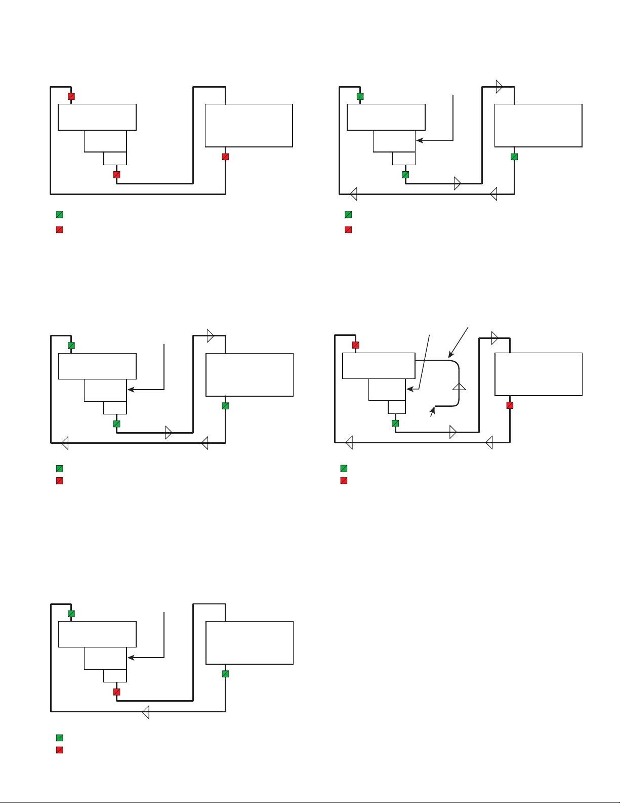
Suck Back Operation Mode
to migrate into the strainer box and over to the
asphalt pump.
12. At this time while the wash down pump is running
and suck back is in auto, change the pump con-
trol from auto to manual, and increase the pump
speed slider about ¾ of the way and start the
pump again.
Adjust the pump GPM to around 60 GPM for
another 10 seconds then turn the pump dial
counterclockwise to the 0 GPM position for
approximately another 10 seconds.
13. Turn the ush valve to the off position, shut off
the wash down pump then hit the power button
to turn off the system.
4

OFFHANDSPRAY SUCK BACK
Handspray Valve Positions
Return
Valve
Open
Hand Spray Valve
Closed
4 Way Valve
Circulate in T
ank
Tank
Valve
Closed
Master
Handspray
Valves Off
Transfer Valve
Closed
Transfer Line
Suck Back Valve
Closed
Flush Valve
Closed
Suck Back
Valve
Open
Transfer Line
cap on and
secured
Load Line cap
on and secured
Bleeder Valve
is last flip lever
valve on wings
Figure 1. Valve Positions for Spray Bar Suck Back
WARNING
To prevent possible burns from hot asphalt
spray, do not stand, or allow anyone to stand,
where accidental opening of a valve may
cause contact with hot asphalt.
CAUTION
When using rear pump control, engine RPM
changes will affect asphalt pump speed.
5

Smart Clean
Tank
Valve
CLOSED
Valve
OPEN
Valve
CLOSED
Power Return
Valve
CLOSED
4 Way Valve in
CIRC IN TANK
Position
Bleeder
Valve
Smart Clean
Tank
Valve
OPEN
Valve
OPEN
Valve
OPEN
Power Return
Valve
CLOSED
4 Way Valve in
CIRC IN BAR
Position
b. Put the PUMP CONTROL to MANUAL.
c. Press Start.
d. Slowly turn speed up until Smart Clean tank
starts to empty (near 150 GPM).
e. Turn the PUMP SPEED CONTROL back to
AUTO to stop the pump. The pump should
now have appropriate vacuum to run in
AUTO Smart Clean modes.
7. During the spray bar Smart Clean period (factory
set to 120 seconds), check Smart Clean Tank
to conrm uid is both draining and returning.
8. After the desired clean time, the Smart Clean
valves will switch into Smart Clean Suck Back.
The pump will change speed to 50 GPM for
15 seconds, then change to 100 GPM for 30
seconds and nish the rest of the cycle time at
150 GPM (factory set at 120 seconds.). This
cycle removes cleaning uid from the bar and
returns it to the Smart Clean tank.
9. During Smart Clean Suck Back, open the bleeder
valve on the left wing of a VWSB or single spray
valve of a standard bar, then lower and raise the
wing. Close the bleeder valve or single spray
valve. Repeat this process for the right wing.
For best results, the spray bar should be in the
raised position for this cycle.
10. Check Smart Clean tank to conrm uid is
returning after the set suck back time (factory
set at 120 seconds). The pump will stop.
NOTE: To stop the pump in either MANUAL
control or AUTO control, press the red Stop Pump
button.
The pump can be stopped by pushing the
EMERGENCY STOP switch OFF.
Spray Bar Smart Clean
At the cab control panel:
Turn on the POWER switch.
At the rear control panel:
1. Turn the EMERGENCY STOP switch ON.
2. Conrm unit is properly sucked back.
3. Press the Bar Clean button on the BAR CLEAN
portion of the Operation Mode (Spray Bar Smart
Clean) (See Figure 2 on page 8).
4. Put the PUMP CONTROL to AUTO.
5. Press START. The pump will start turning at
a preset circulation rate (200 GPM). For two
minutes the system will engage a standard
suckback.
6. After standard suck back is complete, the Smart
Clean valves will switch into Spray Bar Smart
Clean. The pump will start at 100 GPM for 5
seconds then change to 50 GPM for the rest of
the cycle time (factory set at 120 seconds).On
page 8, Figure 3 shows each step of the Bar
Clean cycle, with a countdown timer for how
long the step will run.
NOTE: If uid does not begin to drain from
the Smart Clean tank, the following steps may
need to be done in order to form a vacuum.
a. Press the Bar Clean button on the BAR
CLEAN portion of the Operation Mode
(Spray Bar Smart Clean).
BAR CLEAN SMART CLEAN SUCK BACK
6

Asphalt Pump Smart Clean
At the cab control panel:
Turn the POWER switch ON.
At the rear control panel:
1. Turn the EMERGENCY STOP switch ON.
2. Conrm unit is properly sucked back.
3. Press the Pump Clean button on the BAR CLEAN
portion of the Operation Mode (Spray Bar Smart
Clean) (See Figure 4 on page 8).
4. Put the PUMP CONTROL to AUTO.
5. Press START. The pump will start turning at
a preset circulation rate (200 GPM). For two
minutes the system will engage a standard
suckback.
6. After standard suck back is complete, the Smart
Clean valves will switch into Asphalt Pump
Smart Clean. The pump will start at 100 GPM for
5 seconds then change to 50 GPM for the rest
of the cycle time (factory set at 120 seconds)
On page 8,.Figure 5 shows each step of the
Bar Clean cycle, with a countdown timer for how
long the step will run.
NOTE: If uid does not begin to drain from the
Smart Clean tank, the following steps may need
to be done in order to form a vacuum.
a. Press the Pump Clean button on the BAR
CLEAN portion of the Operation Mode
(Spray Bar Smart Clean).
b. Put the PUMP CONTROL to MANUAL.
c. Press Start.
d. Slowly turn speed up until Smart Clean tank
starts to empty (near 150 GPM).
e. Turn the PUMP SPEED CONTROL back to
AUTO to stop the pump. The pump should
now have appropriate vacuum to run in
AUTO Smart Clean modes.
7. During the spray bar Smart Clean period (factory
set to 120 seconds), check Smart Clean Tank
to conrm uid is both draining and returning.
8. After the desired clean time, the Smart Clean
valves will switch into Smart Clean Suck Back.
The pump will change speed to 50 GPM for 15
seconds, then change to 100 GPM for 30 sec-
onds and nish the rest of the cycle time at 150
GPM (factory set at 120 seconds.). This cycle
removes cleaning uid from the bar and returns
it to the Smart Clean tank.
9. During Smart Clean Suck Back, open the bleeder
valve on the left wing of a VWSB or single spray
valve of a standard bar, then lower and raise the
wing. Close the bleeder valve or single spray
valve. Repeat this process for the right wing.
For best results, the spray bar should be in the
raised position for this cycle.
10. Check Smart Clean tank to conrm uid is re-
turning after the set suck back time (factory set
at 120 seconds). The pump will stop.
NOTE: To stop the pump in either MANUAL
control or AUTO control, press the red Stop Pump
button.
The pump can be stopped by pushing the
EMERGENCY STOP switch OFF.
ASPHALT PUMP SMART CLEAN SMART CLEAN SUCK BACK
Smart Clean
Tank
Valve
OPEN
Valve
OPEN
Valve
OPEN
Power Return
Valve
CLOSED
4 Way Valve in
CIRC IN TANK
Position
Smart Clean
Tank
Valve
CLOSED
Valve
OPEN
Valve
CLOSED
Power Return
Valve
CLOSED
4 Way Valve in
CIRC IN TANK
Position
Bleeder
Valve
7

Figure 2. SmartClean Bar Clean Button
Figure 3. SmartClean Bar Clean Cycle Steps
Figure 4. SmartClean Pump Clean Button
Figure 5. SmartClean Pump Clean Cycle Steps
8

Adjusting Preset Smart Clean
Functions:
Enter the setup screens.
1. Navigate to Setup by pressing the gear icon in
the header. Press the Setup button and enter
password 61061. Smart Clean settings are on
page 1.
2. Use the plus and minus buttons to adjust set-
tings. Smart Suck Back is the time the asphalt
pump sucks back after ushing in Bar Clean or
Pump Clean. Smart Bar Clean and Smart Pump
Clean are the times the asphalt pump ushes
in either. These three settings all have a factory
default of 120 seconds. Press the Save button
on Memory to save settings. The Factory mem-
ory slot cannot be saved over.
3. Tap the oval Etnyre Logo home button to exit
Setup screens and return to the home screen.
To prevent possible burns from foaming
or violent eruption:
Do not transfer the contents of the Smart
Clean Tank if the material temperature in the
Asphalt Tank is over 200ºF or if water and/or
condensation is present in the Smart Clean
Tank or if emulsion was previously ushed
with the Smart Clean system.
WARNING
Empty Smart Clean Tank Into
Main Tank
At the cab control panel:
Turn the POWER switch on.
At the rear control panel:
1. Turn EMERGENCY STOP switch ON.
2. Must be in Bar Clean or Pump Clean.
3. Press and hold Smart Clean Tank Empty button
for 5 seconds. The pump will run for 30 seconds
at 50 GPM. If the tank does not drain completely,
repeat step 3.
CAUTION: This function will put the Smart Clean
solution into the main tank. Be sure you want to
mix before using this function.
EMPTY SMART CLEAN TANK
INTO MAIN TANK
9

Smart Clean Recirculating Flushing System - Optional
23
12 26
27
1
1
9
19
22
17
14
20
13
7
8
3
25
18
6
21
24
5
2
16
4
11
10
15
REF PART NO QTY DESCRIPTION REF PART NO QTY DESCRIPTION
12610041 2BRKT ASSEMBLY-MT, FUEL TANK
23383153 1TANK
32600376 3HANDLE-ASM
46605258 3VALVE-BALL,DBL ACT,1"NPT,AIR
50108686 2ELBOW-PIPE,90,ST,0.50NPT,PN
60144033 1BUSHING-PIPE,0.75X0.25NPT,PN
70144129 1ELBOW-PIPE,90,0.75NPT,PD
82600371 3BOLT-EYE,20" MANHOLE
93360726 4BOLT-HOOK BIT,FRAME TRUCK 5/8
10 3370988 1ANGLE ASM-RH MTG,SMT CLEAN
11 3370989 1ANGLE ASM-LH MTG,SMT CLEAN
12 3383158 1PLATE-LID,SMART CLEAN
13 3383159 1DECAL-SMART CLEAN,LOGO
14 3390570 1PLATE-IDENTIFICATION FUEL TANK
15 5005423 1DECAL-FILL W/RELEASE AGNT ONLY
16 6002390 3NUT-HEX SER FLG,.38NC PD
17 6605204 1CAP-FILLER,FUEL TANK
18 6100880-05 3BOLT-WIZ,0.375UNCX1.50 GR5,PD
19 6200153 1PLUG-PIPE,SQ HD,3.00NPT,PN
20 6200530 1NIPPLE-PP,SCH 80,0.75CL,PD.
21 6500039 1THERMOMETER-2IN.DIAL,9IN DUAL
22 6600162 1COCK-DRAIN,0.25",EXTERNAL SEAT
23 6600323 AR PACKING-3/8SQ,GARLOCK#3/FT
24 6600647 3HOSE END-12X12MP,ST, LPSP
25 6605458 1GAUGE-SPIRAL,14IN,TANKS
26 9413948 4NUT-HEX,LOCK,0.62NC,EA,GRA,PD
27 9422850 4WASHER-FLAT,0.62A(0.65X1.31)HN
AR = As Required
12
3383158
1
PLATE-LID
,
SMART CLEAN
2
23
66003
2
3
AR
PACKING-3/8SQ
,
GARLOCK#3/FT
3
6
01
44
033
1
BU
S
HIN
G
-PIPE,0.75X0.25NPT,P
N
6
10
Other manuals for Black-Topper
6
Table of contents
Other Etnyre Construction Equipment manuals