ETS-Lindgren OMS User manual

www.fmgrupotec.com fmgrupotec@fmgrupotec.com 0034.903.360.306 Calle Algepser n16 Parque Empresarial Tactica- 46980 Paterna (Valencia)- España
Sample Draw
Oxygen
Monitoring System
(OMS)
User Manual

www.fmgrupotec.com fmgrupotec@fmgrupotec.com 0034.903.360.306 Calle Algepser n16 Parque Empresarial Tactica- 46980 Paterna (Valencia)- España
ETS-Lindgren Inc. reserves the right to make changes to any product described
herein in order to improve function, design, or for any other reason. Nothing
contained herein shall constitute ETS-Lindgren Inc. assuming any liability
whatsoever arising out of the application or use of any product or circuit
described herein. ETS-Lindgren Inc. does not convey any license under its
patent rights or the rights of others.
© Copyright 2013 by ETS-Lindgren Inc. All Rights Reserved. No part of this
document maybe copied byany means without written permission from
ETS-Lindgren Inc.
Trademarks used in this document: The ETS-Lindgren logo and OMS are
trademarks of ETS-Lindgren Inc.; NEMA is a registered trademark of NEMA;
3M and Scotch-Brite are trademarks of 3M.
Revision Record
MANUAL,OXYGEN DEFICIENCY MONITOR | Part #399374, Rev. B
Revision
Description
Date
A
Initial Release
August, 2013
B
Updated Introduction; added
installation location information;
added Sample Draw Sensor
Tubing
December, 2013

www.fmgrupotec.com fmgrupotec@fmgrupotec.com 0034.903.360.306 Calle Algepser n16 Parque Empresarial Tactica- 46980 Paterna (Valencia)- España
Table of Contents
Notes, Cautions, and
Warnings..............................................vii
1.0
Introduction..........................................................................9
Technology................................................................................................. 9
Long-Life Zirconium Oxide Sensor Cell............................................... 9
Smart Electronics.............................................................................. 10
Standard Configuration............................................................................. 10
Optional Remote Display.......................................................................... 10
Other Optional Items................................................................................. 11
ETS-Lindgren Product Information Bulletin ............................................... 11
2.0
Maintenance ....................................................................... 13
Recommended Routine Maintenance....................................................... 14
Every 6-12 Months............................................................................ 14
Annually............................................................................................ 14
Replacement and Optional Parts .............................................................. 15
Service Procedures .................................................................................. 15
3.0
Specifications..................................................................... 17
Electrical Specifications ............................................................................ 17
Physical Specifications ............................................................................. 17
Performance Specifications ...................................................................... 18
Gas Detection System Specifications........................................................ 18
Signal Outputs.......................................................................................... 19
Default Factory Settings............................................................................ 19
4.0 Component
Views
..............................................................21
Front View Exterior................................................................................... 21
Front View, Cover Removed..................................................................... 23
Transmitter Interior ................................................................................... 25
Alarm Relay Board.................................................................................... 26
5.0 Before You Begin
Installation...........................................27
Site Requirements.................................................................................... 27
Connect to 24 VDC Regulated Power....................................................... 28
Connect OMS and Sensor Before Powering............................................. 28

www.fmgrupotec.com fmgrupotec@fmgrupotec.com 0034.903.360.306 Calle Algepser n16 Parque Empresarial Tactica- 46980 Paterna (Valencia)- España
Do Not Exchange the Sensor Electronics.................................................. 28
Use Proper Calibration Steps.................................................................... 28
Keep Away From Silicone Compounds..................................................... 29
Keep Away From High Air Flow ................................................................ 29
Keep Away From a Water Stream............................................................. 30
6.0
Installation..........................................................................
31
Mounting the OMS.................................................................................... 31
Transmitter and Sensor..................................................................... 32
Enclosure Mounting Feet .................................................................. 33
Dust Filter......................................................................................... 34
Sample Draw Sensor Tubing.................................................................... 35
Using an Available Waveguide.......................................................... 36
Using Kit 551060 to InstallWaveguide.............................................. 37
Wiring....................................................................................................... 39
Installing the Optional Remote Display...................................................... 40
Connecting a Remote Horn and Strobe to OMS........................................ 42
Connecting a Remote Fan Contactor to OMS........................................... 43
Initial Startup............................................................................................. 44
7.0
Operation ............................................................................
47
Joystick Operation.................................................................................... 47
Main Operation Mode ............................................................................... 48
Internal Sample Flow Rate........................................................................ 48
Signal Outputs.......................................................................................... 48
Instrument Faults...................................................................................... 49
Loss of Power Indicator ............................................................................ 50
Alarm Reset.............................................................................................. 50
8.0 Programming the
OMS
......................................................
51
Program Flowchart ................................................................................... 52
Passwords................................................................................................ 57
Enter Password ................................................................................ 57
Change Password............................................................................. 58
Enable/Disable Password Function................................................... 59
Main Menus and Submenus ..................................................................... 60
Set 4–20 mA Loop............................................................................ 60

www.fmgrupotec.com fmgrupotec@fmgrupotec.com 0034.903.360.306 Calle Algepser n16 Parque Empresarial Tactica- 46980 Paterna (Valencia)- España
Set Formats...................................................................................... 61

www.fmgrupotec.com fmgrupotec@fmgrupotec.com 0034.903.360.306 Calle Algepser n16 Parque Empresarial Tactica- 46980 Paterna (Valencia)- España
Set Alarm Threshold Parity............................................................... 63
Set Latching...................................................................................... 65
Reset Latching Alarm........................................................................ 66
Set Alarm Delay................................................................................ 67
Set Zero Suppression....................................................................... 67
Set Alarm Thresholds ....................................................................... 68
Set Alarm Hysteresis ........................................................................ 70
Set Sensor Adjust............................................................................. 72
9.0 Sensor
Verification ............................................................
73
Required Gas and Equipment................................................................... 74
Sensor Verification Procedure .................................................................. 74
Sensor Verification to Nitrogen.................................................................. 75
Sensor Verification to Known Concentration of Oxygen ............................ 76
Appendix A:
Warranty.............................................................
77

www.fmgrupotec.com fmgrupotec@fmgrupotec.com 0034.903.360.306 Calle Algepser n16 Parque Empresarial Tactica- 46980 Paterna (Valencia)- España
This page intentionally left blank.


vii
www.ets-lindgren.com
Notes, Cautions, and Warnings
Note: Denotes helpful information intended to
provide tips for better use of the product.
Caution: Denotes a hazard. Failure to follow
instructions could result in minor personal injury
and/or property damage. Included text gives proper
procedures.
Warning: Denotes a hazard. Failure to follow
instructions could result in SEVERE personal injury
and/or property damage. Included text gives proper
procedures.
See the ETS-Lindgren Product Information Bulletin for safety,
regulatory, and other product marking information.

This page intentionally left blank.

1.0 Introduction
The ETS-Lindgren Sample Draw Oxygen Monitoring System (OMS™) is a
self-contained oxygen deficiency detection system suitable for remote sampling
of confined spaces; this single-point monitor is designed for the continuous
detection and measurement of ambient oxygen concentration levels.
As a compact gas monitoring system, the OMS is ideal for the continuous
monitoring of the air in MRI rooms, labs, freezers, confined spaces, and other
shielded enclosures where inert gases may displace the oxygen and create a
danger for patients and staff. The OMS is suitable for indoor and outdoor use,
and is intended to be installed outside of the shielded enclosure.
Each system consists of a long-life zirconium oxide sensor cell and 3-wire
transmitter. Unlike electrochemical sensor cells, the zirconium oxide sensor cell
provides stable oxygen readings even in areas where temperature and humidity
levels are changing. The OMS may be used as a standalone gas detector or
connected to your own centralized control and surveillance system.
Technology
L
ONG
-L
IFE
Z
IRCONIUM
O
XIDE
S
ENSOR
C
ELL
The heart of the monitoring system is a zirconium sensor, which responds to low
oxygen conditions within seconds and provides accurate measurements over a
wide temperature and humidity range. The zirconium sensor will operate
continuously for eight or more years, requiring minimum maintenance. There are
no zero or span calibration pots to adjust, and when compared to disposable
sensors, the long-life zirconium sensor can save hundreds of dollars in annual
maintenance.
Unlike concentration cells, the zirconium sensor does not need an oxygen
reference gas for proper operation. The OMS can detect low oxygen levels in
confined spaces and process tools without the need of a reference gas.
S
MART
E
LECTRONICS
The OMS incorporates a special electronic circuit that continuously monitors
sensor operation.With the addition of the alarm relay option, any cell degradation
or complete failure will be detected immediately. This smart circuitry alerts the
user to sensor faults and other electrical problems that may interrupt surveillance
through the standard mA signal output signal or through the optional fault relay
option.
Ideal for continuously monitoring oxygen levels in confined spaces or areas
where inert gases are used, the OMS does not drift or lose sensitivity with
weather or temperature changes. The electronics are housed in a
NEMA Type 4X enclosure.
Standard Configuration
The OMS must be installed outside of the shielded enclosure.
•Oxygen Monitoring System
•Power supply
•Dust filter
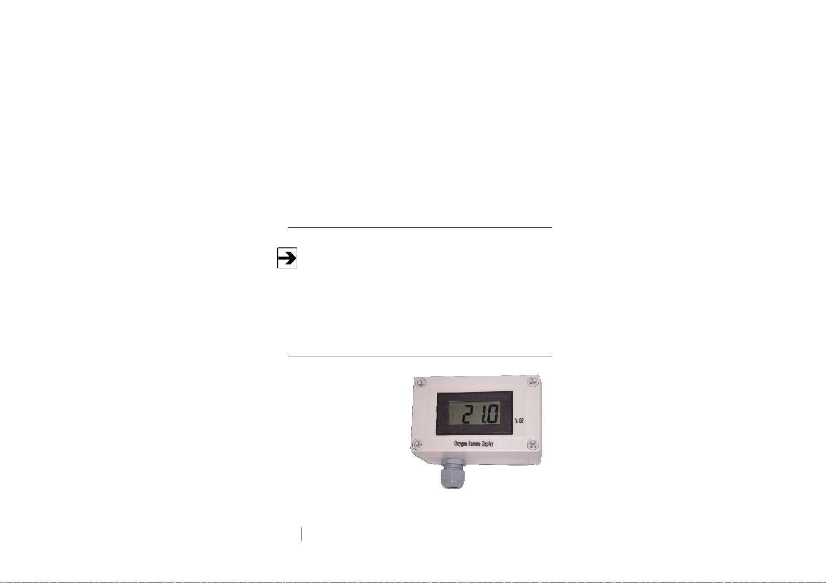
Optional Remote Display
The remote display receives oxygen
concentration information from
the OMS. Up to two remote displays
can be connected. See page 40 for
installation information.

Other Optional Items
•Remote Horn and Strobe
•Waveguide Installation Kit
ETS-Lindgren Product Information Bulletin
See the ETS-Lindgren Product Information Bulletin included with your shipment
for the following:
•Warranty information
•Safety, regulatory, and other product marking information
•Steps to receive your shipment
•Steps to return a component for service
•ETS-Lindgren calibration service
•ETS-Lindgren contact information

This page intentionally left blank.
13
2.0 Maintenance
WARRANTY
Calibrate or challenge the OMS ONLY outside
the MRI suite.
Before performing anymaintenance, follow the
safetyinformation in the ETS-Lindgren
Product Information Bulletin included with your
shipment.
Maintenance of the OMS is limited to the
procedures described in this manual, and
should be performed onlyby qualified
personnel.
Warranty may be void if non-authorized
procedures are performed, or if performed by
non-qualified personnel.
If you have any questions concerning
maintenance, contact ETS-Lindgren
Customer Service.

14
Maintenance
Recommended Routine Maintenance
The Sample Draw Oxygen Monitoring System (OMS™) is a continuous gas
detection system that measures and detects hazardous gas leaks in the
workplace, and therefore requires periodic maintenance to ensure proper
operation. The frequency with which this routine maintenance is performed
depends on your environment and company policies. Following are
recommendations intended as a general guideline.
E
VERY
6-12 M
ONTHS
•Visual checks: Check for power and proper operation. The OMS
should output a 17.34 mA signal when the oxygen level is at 20.9%.
Also, the display should indicate 20.9% oxygen when the oxygen is at
ambient levels.
•Sensor verification with nitrogen: The ambient oxygen level is
20.9%; therefore, under ambient conditions verification of the OMS to
20.9% oxygen is constantly performed. The OMS requires periodic
testing with nitrogen only to verify the cell response to low oxygen
levels. See Sensor Verification on page 73 for detailed steps.
A
NNUALLY
Depending on the environment, the filter should be replaced every 12 months; in
dusty environments, the filter may need to be replaced more frequently. If the
filter becomes completely blocked, the internal flow sensor will detect the loss of
flow and activate the fault relay and LED.
15
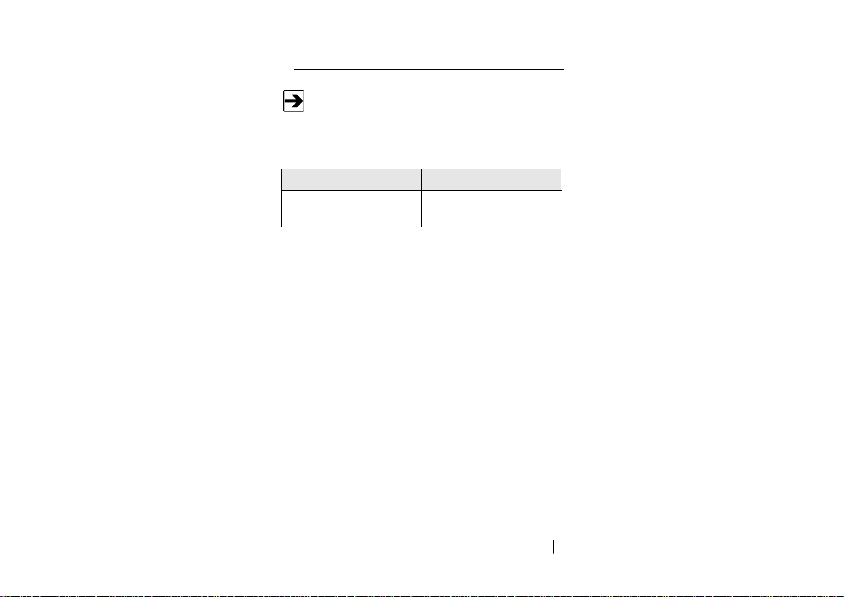
Replacement and Optional Parts
ETS-Lindgren may substitute a similar part or new part number with
the same functionality for another part/part number. Contact
ETS-Lindgren for questions about part numbers and ordering parts.
Following are the part numbers for ordering replacement or optional parts for
the OMS.
Part Description
Part Number
Optional Remote Display
250552
Filter Replacement
250551
Service Procedures
For the steps to return a system or system component to ETS-Lindgren for
service, see the Product Information Bulletin included with your shipment.

16
Maintenance
This page intentionally left blank.

17
3.0 Specifications
Electrical Specifications
A regulated 24 VDC power supply is required.
Power:
24 VDC external power
Consumption:
Approximately 700 mA
Physical Specifications
Height:
7.0 in (178 mm)
Width:
5.0 in (127 mm)
Depth:
5.0 in (127 mm)
Weight:
4.0 lb (2 kg)
Enclosure Type:
NEMA Type 4X wall mount general
purpose; not intended for explosive
atmospheres or
electrically-classified areas

18
Specifications
Performance Specifications
Sensor Type:
Long-life zirconium oxide
sensor cell, 0%–25%
Response Time:
Within 2 seconds of any change in
oxygen
Repeatability:
± 2% of reading
Fault Indicators:
•Loss of VDC power
(analog signal drops to 0 mA).
•Sensor cell failure: fault relay
activated
Operating Temperature:
-40°C to + 40°C (40°F to 104°F)
Contact ETS-Lindgren for lower or
higher operating temperatures
Humidity:
0% to 95% relative humidity (RH)
Contact ETS-Lindgren for sensors
which can operate in 100%
condensing RH environments
Gas Detection System Specifications
Type:
Long-life zirconium oxide
sensor cell, 0%–25%
Sensor Life:
8 to10 years, under normal
conditions
Transmitter:
•Microprocessor electronics with
built-in 3-digit backlit LCD display
•Joystick-operated menus
Other manuals for OMS
1
Table of contents
Popular Laboratory Equipment manuals by other brands

Hanil
Hanil Ultra 5.0 quick guide

Thermo Scientific
Thermo Scientific STANDARD Series manual

Swan Analytical Instruments
Swan Analytical Instruments AMI Turbiwell Operator's manual

Miltenyi Biotec
Miltenyi Biotec CliniMACS Plus System user manual

Thermo Scientific
Thermo Scientific HyPerforma 5.1 S.U.B. Hardware Integrator Guide

Thermo Scientific
Thermo Scientific Medifuge Instructions for use

Thermo Scientific
Thermo Scientific STANDARD Series instructions

Beckman Coulter
Beckman Coulter JA-25.50 Instructions for use

seward
seward STOMACHER 3500 Series Service and maintenance manual

LW Scientific
LW Scientific BVC-4k16-CMT3 instruction manual

Radleys
Radleys Carousel 12 Plus instructions

Parata
Parata Mini Customer guide


