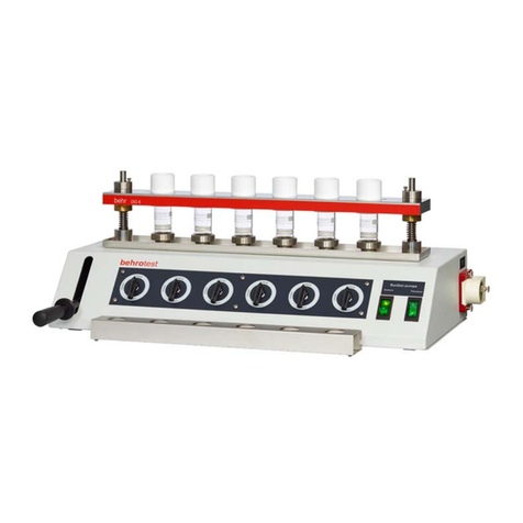
seward STOMACHER 3500 Series Installation and user guide

STOMACHER 80/ 400 CLASSIC/ 400 CIRCULATOR/ 3500 Series
MAINTENANCE INSTRUCTIONS
1
STOMACHER
SERVICE
AND MAINTENANCE
MANUAL

STOMACHER 80/ 400 CLASSIC/ 400 CIRCULATOR/ 3500 Series
MAINTENANCE INSTRUCTIONS
2
This electronic manual consists of 3 parts.
1. The general notes presented here on tackling service and maintenance
issues.
2. A set of Stomacher schematics with parts identification annotations.
3. Spare parts number and description list.
These sections are all on the CD ROM as separate files in .pdf and .doc format.
Please contact SEWARD SERVICE if you have any queries or require advice on
any issue:
PHONE +44 (0) 1903 236411
FAX +44 (0) 1903 219233
EMAIL info@seward.co.uk

STOMACHER 80/ 400 CLASSIC/ 400 CIRCULATOR/ 3500 Series
MAINTENANCE INSTRUCTIONS
3
WARRANTY & SERVICE POLICY
All Seward Stomacher are protected by a 36 month warranty covering faulty
workmanship and materials. In the event of a fault occurring within this period please
contact Seward Customer Service who will arrange the collection / return of the
instrument for warranty repair and/or replacement at Seward’s discretion.
The warranty is void if the device has been damaged as a result of unauthorised
service, lack of routine maintenance, modification or subject to neglect, misuse,
accident, improper installation or operation.
The Seward Stomacher has been designed to give durable service with a minimum of
maintenance. Construction is of a modular form enabling major sub- assemblies to be
readily removed and replaced thereby minimising downtime in the unlikely event of a
failure.
Seward Ltd are can provide spare parts but are unable to accept any liability implied
or otherwise for the incorrect fitting of such parts or cost incurred in the fitting of any
replacement parts by third parties.
SAFETY RECOMMENDATIONS
Internal servicing and maintenance should be performed by suitably qualified, trained
and authorised personnel fully conversant with this type of equipment. Prior to
commencement of work it is recommended that this manual be studied fully. Seward
Ltd accepts no responsibility implied or otherwise for any damage, loss or injury as the
result of incorrect use, maintenance or interpretation of these instructions.
CAUTION:- High voltages are present on the main PCB, transformer, etc.; at all times
whilst the instrument is powered “on”. The correct safety procedures should therefore
be strictly adhered to during the course of all maintenance work.
RECOMMENDED TOOLS FOR SERVICING
The tools listed below are those considered by Seward to be the most appropriate for
service and maintenance of the Stomacher 400.
Hexagon socket ball wrenches - 2.5 mm, 3.0 mm & 5.0 mm sizes
Open end spanner (extra thin series) - 19/32” A/F.
Large screwdriver - 150 mm blade length.
Small electrical screwdriver - 75 mm blade length.
Ball pien hammer - 500 gram size.
Pin punch - 3mm size.
External right angle circlip pliers - 0 to 12 mm size.
Multi-meter - any basic model
Starlock dome washer application tool - 11 mm size.

STOMACHER 80/ 400 CLASSIC/ 400 CIRCULATOR/ 3500 Series
MAINTENANCE INSTRUCTIONS
4
Bush insertion tool - Contact Seward Ltd
In the event of difficulty obtaining any item please contact Seward Customer Service.
The correct use of hand tools to remove fasteners, wiring terminations and other
conventional components is assumed
ROUTINE SERVICING
It is recommended that the following routine checks be carried out at six monthly
intervals unless local regulations or Codes of Practice require more frequent service
intervals. If the instrument is extensively use, i.e.; double shift working, then it is
recommended to reduce the service interval to three months.
Functional Check
•Run the instrument and ensure all available functions are working correctly.
•Check speeds and times are within specification.
•Take note of any excessive noise, this may be indicative of worn connectors.
Electrical Check
•Check the security of all terminal/ plug connections.
•It is considered good practise to periodically test the instrument using a portable
appliance tester and particularly following any electrical repair.
Mechanical Checks
•Check the security of all fastenings, but avoid over tightening.
•Check paddle clearance, a tapping sound from the paddles striking the inside
face of the door is indicative of adjustment being required.
•Clean the paddle faces, residue build-up could cause bag damage.
•Examine the rubber connectors for signs of deterioration, always replace as a
pair as necessary.
•Examine the knuckle pivots, checking for bearing wear, replace as necessary.
•Check the paddle shaft bearings, replace if any radial wear is detected.
•Lubricate the paddle shaft bearings; apply two to three strokes from an oil gun
containing SA30 to each oil nipple. DO NOT over lubricate as this may cause oil
to forced past the seals. DO NOT USE GREASE UNDER ANY
CIRCUMSTANCE.
•Ensure eccentrics are tight on the gearbox output shafts.
•Check the door mechanism linkage for absence of excessive play.
• Check the operation of the door interlock switch.

STOMACHER 80/ 400 CLASSIC/ 400 CIRCULATOR/ 3500 Series
MAINTENANCE INSTRUCTIONS
5
TROUBLE SHOOTING
When experiencing a problem and before consulting the fault diagnosis charts that
follow, please ensure that all electrical connection, plugs and sockets are firmly and
correctly engaged.
Please be aware that the instrument incorporates an overload protection circuit within
the controller and limits the current draw to prevent the risk of overheating or other
damage.
Under adverse conditions the motor may take a little more time to build up sufficient
torque to start and run at the selected speed. These conditions are:-
1. Upon initial start up following a period of transportation or storage.
2. The instrument has been stored or is in a cold environment i.e. less than 10 C.
3. Overloading the instrument due to the nature of the sample.
4. The paddle shafts are tight in their bearings, possibly following the incorrect
replacement of the bearings.
The above can be overcome in the following manner:-
1. Run for 5 to 10 minutes with a number of stop/start cycles
2. Allow the instrument to stand in a warmer environment i.e. above 10 C, for at least
2 hours then run for 5 to 10 minutes with a number of stop/start cycles.
3. Reduce the sample size.
4. Ref.. to section on paddle shaft bearings.
In the event of being unable to reach a diagnosis please contact Seward Customer
Service.

STOMACHER 80/ 400 CLASSIC/ 400 CIRCULATOR/ 3500 Series
MAINTENANCE INSTRUCTIONS
6
Mains Lead
Connected ? Connect
FAULT DIAGNOSIS
CHART No. 1
FAULT DESCRIPTION
Y
N
Instrument
Mains Lead Replace Fuse
N
N
Y
Y
Y
Mains Inlet Replace Fuse(s)
Rocker Switch Replace Switch
will not
power up
Fuse Failed ?
Fuse(s) Failed ?
Faulty ?

STOMACHER 80/ 400 CLASSIC/ 400 CIRCULATOR/ 3500 Series
MAINTENANCE INSTRUCTIONS
7
Keypad PCB
Connected ? Connect
FAULT DIAGNOSIS
CHART No. 2
FAULT DESCRIPTION
Y
N
Mains Indicator
'ON' Instrument
will not run.
Is 'LCD'
Functioning ? Go to Chart 3
Y
N
N
Y
N
Stall Icon
Indicated
on LCD ? Go to Chart 4
Press 'RUN'
Button (Green)
Unit runs ?
Door Switch
Adjustment
And/Or Faulty

STOMACHER 80/ 400 CLASSIC/ 400 CIRCULATOR/ 3500 Series
MAINTENANCE INSTRUCTIONS
8
Transformer Replace
FAULT DIAGNOSIS
CHART No. 3
FAULT DESCRIPTION
N
Y
12v Supply CheckN
From Chart 2 12v Fuses
Failed ?
present at
Transformer ? Transformer
Y
Keypad or
Control PCB
Faulty

STOMACHER 80/ 400 CLASSIC/ 400 CIRCULATOR/ 3500 Series
MAINTENANCE INSTRUCTIONS
9
PCB Motor Paddles
FAULT DIAGNOSIS
CHART No. 4
FAULT DESCRIPTION
N
Y
From Chart 2
110v Supply Check
Y
N
N
Y
Y
PCB Faulty ? Replace
Drive Unit Replace
Protection
Fuse Failed ? Jammed or
seized ?
Remove
obstruction or
resolve seizure
Replace Fuse
present at
Transformer ? Transformer
Faulty ?
Y

STOMACHER 80/ 400 CLASSIC/ 400 CIRCULATOR/ 3500 Series
MAINTENANCE INSTRUCTIONS
10
Keypad PCB Replace
FAULT DIAGNOSIS
CHART No. 5
FAULT DESCRIPTION
N
Y
Instrument
Drive Replace
Y
Faulty ?
runs but at
incorrect speed
Controller
PCB Faulty ?
Keypad PCB Replace
FAULT DIAGNOSIS
CHART No. 6
FAULT DESCRIPTION
N
Y
Instrument
Drive Replace
Y
Faulty ?
runs but for
incorrect time
Controller
PCB Faulty ?

STOMACHER 80/ 400 CLASSIC/ 400 CIRCULATOR/ 3500 Series
MAINTENANCE INSTRUCTIONS
11
STOMACHER ELECTRONIC SERVICE PROCEDURES
To replace the Drive Control PCB remove the rear cover and disconnect the main loom
plug and the ribbon cable from the Keypad PCB. Remove the socket cap screws
holding the PCB taking care not to cause any damage. Replacement is the reverse
procedure, ensure the connectors are fully inserted.
Keypad Display PCB Replacement
To replace the Keypad Display PCB remove the rear cover and disconnect the ribbon
cable from the Drive Control PCB. Remove the socket cap screws holding the PCB
taking care not to cause any damage. Replacement is the reverse procedure, ensure
the connectors are fully inserted.
Transformer & Choke Replacement
Removal and replacement of the transformer and choke is straightforward by the
removal of the screw fasteners. The choke terminations are soldered to the loom
requiring replacement and removal by this method. It is imperative that the outputs on
the transformer are replaced in exactly the same positions as they were prior to
dismantling. Refer to block wiring diagram.
Door Interlock Micro Switch Replacement
The door interlock micro switch is actuated by a ramp incorporated into the adjacent
rotating link. The switch is retained by two thin brass lock nuts threaded onto the shank
of the switch and positioned either side of the main body wall through which the shank
passes.
To adjust the switch slacken both lock nuts and rotate the appropriate nut to move the
switch in the desired direction. Re-tighten carefully avoiding excessive force, which
could damage the thread of the switch body. To remove the switch detach the loom
wiring and remove the outside lock nut allowing the switch to be remove from the inside
of the instrument.

STOMACHER 80/ 400 CLASSIC/ 400 CIRCULATOR/ 3500 Series
MAINTENANCE INSTRUCTIONS
12
STOMACHER MECHANICAL SERVICE PROCEDURES
General Description
All threads tapped ISO metric course. The door and door links are stainless steel; the
rear cover is sheet steel. The paint finish is stoved for durability.
NOTE -Care should be taken not to over tighten any fastener, as this may cause
damage to the threads in the casting. If in doubt the recommended tightening torque's
listed below should be adhered to:-
Screw Size (mm) Torque (Nm)
M3 0.95
M4 2.22
M5 4.00
M6 5.40
Door, Handle & Bag Clamp
After long periods of use the paint may wear away from the inside face of the door, this
is quite normal and no cause for concern as the door is constructed of stainless steel.
The door is removed by prising off the two starlock dome washers, releasing the links
and lifting the door off of it’s bottom pivots with a sharp lifting movement.
The bag clamp, complete with door linkage, is removed by undoing the bag clamp
fastening that attaches it to the main body. The linkage should not normally require
attention.
Drive Unit.
The motor gearbox drive unit is sealed with no requirement or provision for
maintenance and if faulty must be replaced as a complete unit. After extreme periods
of service it may be necessary to replace the motor brush gear, in this event contact
Seward Customer Service for advice.
The drive unit is secured to the aluminium motor mounting block by four socket cap
screws, DO NOT SLACKEN, unless it is necessary to replace the drive unit. The motor
mounting block runs in machined guides in the main body to provide paddle clearance
adjustment relative to the inside face of the door. The motor block adjusting screw is
captive within the motor mounting block and threaded into the main body to facilitate
and provide retention of adjustment. The motor mounting block has slotted holes and is
retained to the main body by four socket cap screws. These retaining screws must be
slackened before attempting to turn the motor block adjusting screw and always re-
tighten after adjustment.
To remove the drive it is advised to remove the connector.

STOMACHER 80/ 400 CLASSIC/ 400 CIRCULATOR/ 3500 Series
MAINTENANCE INSTRUCTIONS
13
If the drive unit is released from the motor mounting block, it should be re-aligned using
normal engineering methods such as a dial indicator. However, with experience it is
possible to re-align by a combination of eye and “double tapping” as described later.
Replacement is the reverse procedure and it is recommended that new spring tension
pins be fitted.
Paddles & Connector Assemblies
The flexible connectors are subjected to compression by the Stomaching process and
may deteriorate depending on the degree of use and application. Therefore, they
should be routinely inspected. We recommend that to ensure optimum performance
and to reduce potential down time of the instrument that connectors, if and when
replaced, are done so as a pair and that the ball journal bearings and paddle pivot pin
bushes are simultaneously replaced.
To replace the connector assembly remove the rear cover, slacken the socket cap
screws retaining the motor mounting block to the main body and, with the paddles in
maximum stroke position, turn the motor block adjusting screw so the to retract the
drive unit fully to the rear of the instrument. Remove one of the circlips from the clevis
pivot pin and remove the pin. Release the eccentrics from the gearbox output shafts by
driving out the spring tension pins with a pin punch. It is now possible to remove the
clevis from the cap end by driving out the spring tension pin and the eccentric by
removing the circlip and pressing the eccentric out. The new connector assemblies are
supplied with the ball journal bearing fitted. Replacement is the reverse procedure,
always fit new spring tension pins. Adjust the paddle clearance as described in 7.6,
refit rear cover and test.
The paddles are a stainless steel fabrication and in the event of damage should be
replaced, DO NOT attempt to straighten or repair a damaged shaft. When fitting new
paddles we recommend that new paddle bushes are also fitted.
Paddles Shaft Bushes
Oilite bushes pressed into the main body support the paddle shafts. These bushes are
of sintered construction and are impregnated with lubricant during their manufacture.
Oil nipples are provided to allow additional lubrication as detailed in routine
maintenance.
If the bushes require replacement it is necessary to remove the rear cover, connector
assemblies, drive unit and paddles. Remove the worn bushes using a drift of 8 - 10mm
diameter, engaging on the inner end of the bush being removed. Avoid damaging the
bore if possible. Insert the first new bush using the insertion tool, contact Seward Ltd,
insert the second bush ensure the mandrel of the insertion tool passes through the first
bush to ensure bore alignment. Check the fit of each paddle, the paddle should slide
easily and smoothly in the bush bores with minimum resistance and NO radial play.
Any tightness should be eased by manipulating the paddle shaft in a circular twisting
motion, thereby burnishing the bores, until the desired fit is achieved. In extreme
cases, use of an expanding reamer rotated backwards (anti-clockwise) to improve the

STOMACHER 80/ 400 CLASSIC/ 400 CIRCULATOR/ 3500 Series
MAINTENANCE INSTRUCTIONS
14
fit. UNDER NO CIRCUMSTANCES should any material be reamed from the bush as
this will cause the bush to “bleed” excessive lubricant.
Re assemble all components, adjust the paddle clearance.
Paddles Clearance Adjustment
After carrying out any of the procedures it will be necessary to check and/or adjust the
paddle clearance.
To adjust the paddle clearance, remove the rear cover; slacken the socket cap screws
holding the motor mounting plate to the main body. DO NOT slacken the screws
holding the drive unit to the motor mounting plate otherwise alignment will be lost. Turn
the motor block adjusting screw until each paddle just touches the inside face of the
door when the paddles are at their maximum forward stroke position.. If the instrument
is run briefly the alternate tapping noise of each paddle touching the door should be
just audible. Take up any backlash in the motor block adjusting screw and turn it back
one to one and a quarter turns. Tighten the socket cap screws retaining the motor
mounting plate and refit the cover. If correctly adjusted the ‘double tap’ of the paddles
should be just audible when the front of the door is flexed inwards by hand whilst the
instrument is running.
This manual suits for next models
3
Table of contents
Other seward Laboratory Equipment manuals
Popular Laboratory Equipment manuals by other brands

Novus
Novus NV-8000PS/HP user manual
Diesse
Diesse Ves-Matic Cube 200 Service manual
Thermo Scientific
Thermo Scientific Precision GP 02 user manual
Renfert
Renfert Twister pro instruction manual
Cisco
Cisco AIR-PWRINJ-60RGD1 Series installation instructions

Hauschild
Hauschild SpeedMixer DAC 400.2 VAC-P user manual
