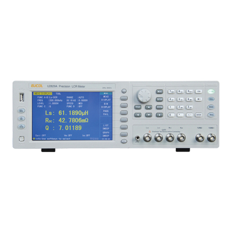
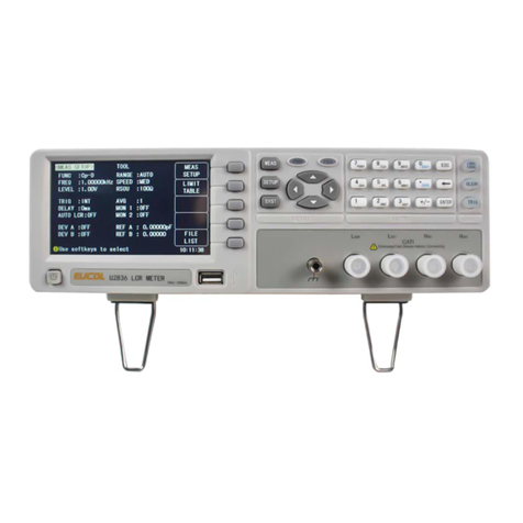
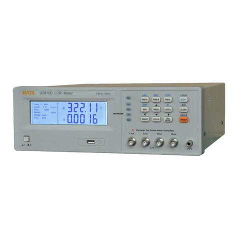
EUCOL U2684 User manual

O
OP
PE
ER
RA
AT
TI
IO
ON
N
M
MA
AN
NU
UA
AL
L
U2684InsulationResistanceMeter
C
C
Ch
h
ha
a
an
n
ng
g
gz
z
zh
h
ho
o
ou
u
u
E
E
Eu
u
uc
c
co
o
ol
l
l
E
E
El
l
le
e
ec
c
ct
t
tr
r
ro
o
on
n
ni
i
ic
c
c
T
T
Te
e
ec
c
ch
h
hn
n
no
o
ol
l
lo
o
og
g
gy
y
y
C
C
Co
o
o.
.
.
,
,
,
L
L
Lt
t
td
d
d.
.
.
A
A
Ad
d
dd
d
d:
:
:No.1,NorthZiyangRoad,TianningDistrict,Changzhou,Jiangsu
T
T
Te
e
el
l
l:
:
:(
(
(0
0
05
5
51
1
19
9
9)
)
)8
8
85
5
55
5
50
0
05
5
51
1
19
9
99
9
9
F
F
Fa
a
ax
x
x:
:
:(
(
(0
0
05
5
51
1
19
9
9)
)
)8
8
85
5
55
5
50
0
05
5
51
1
16
6
69
9
9
E
E
E‐
‐
‐m
m
ma
a
ai
i
il
l
l:
:
:
S
S
Sa
a
al
l
le
e
es
s
s@
@
@e
e
eu
u
uc
c
co
o
ol
l
l.
.
.c
c
co
o
om
m
m.
.
.c
c
cn
n
n
W
W
We
e
eb
b
bs
s
si
i
it
t
te
e
e:
:
:
h
h
ht
t
tt
t
tp
p
p:
:
:/
/
//
/
/
w
w
ww
w
ww
w
w.
.
.e
e
eu
u
uc
c
co
o
ol
l
l.
.
.c
c
co
o
om
m
m.
.
.c
c
cn
n
n

U2684OperationManualVer.1.3
Contents
Contents
1)IntroductiontoInstrument,UnpackingandInstalling......................................................7
1.1IntroductiontoInstrument.................................................................................7
1.2Unpacking...........................................................................................................7
1.3PowerConnection..............................................................................................7
1.4Fuse.....................................................................................................................8
1.5Environment.......................................................................................................8
1.6UseofTestFixture..............................................................................................8
1.7Warm‐up.............................................................................................................8
1.8OtherFeatures....................................................................................................8
2)IntroductiontoFrontandRearPanels..............................................................................9
2.1IntroductiontoFrontPanel................................................................................9
2.2IntroductiontoRearPanel...............................................................................10
2.3DisplayZone.....................................................................................................12
2.4IntroductiontoButtonsonFrontPanel...........................................................12
2.4.1[MEAS]..............................................................................................................12
2.4.2[MEASSETUP]...................................................................................................13
2.4.3[SYSTEM]...........................................................................................................13
2.5SimpleOperation..............................................................................................13
2.6StartingUp........................................................................................................13
3)BasicOperation...............................................................................................................15
3.1<MEASDISP>....................................................................................................15
3.2<MEASSETUP>.................................................................................................15
3.2.1MEASMODE.....................................................................................................16
3.2.2VOLTSET...........................................................................................................16
3.2.3CHARTIME........................................................................................................17
3.2.4RANGE...............................................................................................................17
3.2.5SPEED................................................................................................................18
3.2.6OPENCLR..........................................................................................................18
3.2.7TRIGSRC...........................................................................................................19

U2684OperationManualVer.1.3
Contents
3.2.8AVERAGE...........................................................................................................19
3.2.9INPUTRES.........................................................................................................20
3.2.10CONTCHK.........................................................................................................20
3.2.11LINEFREQ.........................................................................................................21
3.3<LIMITTABLE>..................................................................................................21
3.3.1COMPARER.......................................................................................................21
3.3.2COMPMOD......................................................................................................22
3.3.3COMPPAR........................................................................................................22
3.3.4NOMINAL..........................................................................................................22
3.3.5PASSALMorFAILALM.....................................................................................23
3.3.6LMTL01............................................................................................................23
3.4StartTest...........................................................................................................23
3.4.1TestMethod.....................................................................................................23
3.4.2OperationProcess............................................................................................24
4)SYSTEMandFILE..............................................................................................................25
4.1<SYSTEM>.........................................................................................................25
4.1.1SKIN...................................................................................................................25
4.1.2LANGUAGE........................................................................................................25
4.1.3PASSALARM.....................................................................................................26
4.1.4FAILALARM......................................................................................................26
4.1.5KEYSOUND.......................................................................................................26
4.1.6PASSWORD.......................................................................................................27
4.1.7SAVETYPE.........................................................................................................27
4.1.8BUSMODE........................................................................................................27
4.1.9BAUDRATE.......................................................................................................28
4.1.10DATA/TIME.......................................................................................................28
4.2SYSTEMINFORMATION....................................................................................28
4.3FIRMWAREUPDATE..........................................................................................29
4.4SYSTEMTEST.....................................................................................................29
4.5<FILE>................................................................................................................30

U2684OperationManualVer.1.3
Contents
4.5.1Setupfileforsingle‐groupcomponent(*.EST).................................................30
4.5.2U‐diskmanageperformance............................................................................31
4.5.3Operationstepsforfilemanagement..............................................................31
5)PerformanceIndex............................................................................................................1
5.1MeasurementFunction......................................................................................1
5.1.1MeasurementParametersandNotations..........................................................1
5.1.2Range..................................................................................................................1
5.1.3Trigger.................................................................................................................1
5.1.4ModeofTestTerminal.......................................................................................1
5.1.5MeasurementSpeed(whenMEASDISP&BINDISPissetasOFF)....................1
5.1.6DisplayDigits......................................................................................................2
5.2TestSignal...........................................................................................................2
5.2.1OutputVoltageRange........................................................................................2
5.2.2OutputVoltageAccuracy....................................................................................2
5.2.3MaximumDisplayRange....................................................................................2
5.3MeasurementAccuracy......................................................................................2
5.3.1BasicAccuracyforResistanceMeasurement.....................................................3
6)RemoteControl.................................................................................................................4
6.1RS232CConnection............................................................................................4
6.2SCPI(StandardCommandsforProgrammableInstruments).............................5
6.3USBTMCRemoteControlSystem.......................................................................5
6.3.1SystemConfiguration.........................................................................................5
6.3.2InstalltheDriver.................................................................................................6
6.4USBVCOMVirtualSerialPort..............................................................................7
6.4.1SystemConfiguration.........................................................................................7
6.4.2InstallingDriver...................................................................................................7
7)SCIPCommandReference.................................................................................................8
7.1U2684SubsystemCommands............................................................................8
7.1.1DISPlaySubsystemCommands...........................................................................8
7.1.2FUNCtionSubsystemCommands.......................................................................9

U2684OperationManualVer.1.3
Contents
7.1.3DISChargeSubsystemCommands....................................................................14
7.1.4TRIGgerSubsystemCommands........................................................................14
TRIGger:SOURceBUS..............................................................................................14
HOLD........................................................................................................................................14
7.1.5FETCH?SubsystemCommands........................................................................15
7.1.6COMParatorSubsystemCommands................................................................16
RESistance...............................................................................................................................18
PULSe.......................................................................................................................................19
7.1.7SYSTemSubsystemCommands........................................................................20
7.1.8MassMEMorySubsystemCommands.............................................................21
7.2GPIBCommonComamnds...............................................................................21
8)HandlerInterface............................................................................................................23
9)PackageContentsandWarranty.....................................................................................26
9.1PackageContents.............................................................................................26
9.2Marks................................................................................................................26
9.3Package.............................................................................................................26
9.4Shipping............................................................................................................27
9.5Storage..............................................................................................................27
9.6Warranty...........................................................................................................27

U2684OperationManualVer.1.3
Contents
Declaration
Thedescriptionscontainedinthismanualmaynotcoverallinformationaboutthisinstrument.
Introductionstotheimprovementsoftheinstrumentinperformance,function,internalstructure,
outerappearance,accessories,packingmaterial,etc.aresubjecttochangewithoutnotice.Ifyou
findanyinconformityofthismanualwithourinstruments,pleasecontactusforfurther
consultationbytheaddresslistedonthecover.

U2684OperationManual
Contents
1) IntroductiontoInstrument,Unpackingand
Installing
Thankyouforyourpurchaseanduseofourproducts!Thischapterwillintroducethebasic
instrumentperformance,whichisfollowedbynotesofunpackingandinstalling.
1.1IntroductiontoInstrument
With5‐inch,colorLCDscreenanduniqueinsulationresistance/leakagecurrentdualtestfunction,
U2684InsulationResistanceMeterisanintelligentmeasurementinstrumentthatisusedforrapid
measurementsoninsulatingpropertiesofelectronicpartsandcomponents(especiallythe
capacitance),dielectricmaterial,equipments,wires,cables,etc.
U2684isprovidedwithsortingoutputandexternalsinglepulsesignalinputinterface,makingit
easyforpipelineoperation.Thequippedcommunicationinterfacecanachievetheoff‐site
operationsofallfunctionsoftheinstrumentthroughmicrocomputer.Theinstrumenthasa
powerfulanti‐jammingcapability,whichmakesthemeasurementmorereliable
1.2Unpacking
Inspecttheshippingcontainerfordamageafterunpackingit.Itisnotrecommendedtopoweron
theinstrumentinthecaseofadamagecontainer.
Ifthecontentsinthecontainerdonotconformtothepackinglist,notifyusoryourdealer.
1.3PowerConnection
1) Powersupply:90Vto121Vac(60Hz)or198to242Vac(50Hz).
2) Powersupplypowerrange:≤50VA.
3) L(linewire),N(neutralwire)andE(earthgroundwire)ofthepowersupplyinputsocket
shouldcorrespondtothepowerplugoftheinstrument.
4) Theinstrumenthasbeenspeciallydesignedfordecreasingnoisejammingcausedbytheinput
inACpowerterminal,butitisalsorecommendedtouseitintheenvironmentoflownoise.If
noisescannotbeavoided,installapowersourcefilterplease.
WARNING:Toavoidinjurytopersonnelanddamagetotheinstrumentresultingfromelectric
shock,dosurethattheearthgroundwireissafelygrounded.

U2684OperationManual
Contents
1.4Fuse
Thefuseisastandardconfiguration,sousetheincludedcustomfuseplease.
1.5Environment
1) Donotstoreorusetheinstrumentwhereitcouldbeexposedtomanydusts,greatvibration,
directsunshineandcorrosivegas.
2) Theinstrumentshouldoperateunderthetemperaturerangingfrom10℃to40℃,relative
humidityofnogreaterthan90%.Forhighaccuracy,usetheinstrumentintheenvironment
abovementioned.
3) Forhighaccuracy,donotblocktheleftairventsoastoensuregoodventilation.
4) TheinstrumenthasbeenspeciallydesignedfordecreasingnoisejammingcausedbytheAC
powerinput,butitisalsorecommendedtouseitintheenvironmentoflownoise.Ifnoise
cannotbeavoided,installapowerfilterplease.
5) Iftheinstrumentwillnotbeusedforalongtime,pleaseplaceitintheoriginalorasimilar
packingbox.Theenvironmenttemperatureshouldbekeptintherangeof0℃to40℃,and
therelativehumidityshouldnotbegreaterthan90%RH.Theboxshouldbelocatedinanairy
roomwhereitcouldbeexposedcorrosiveimpuritiesanddirectsunlight.
6) TestleadsontheinstrumentthatareconnectedtoDUTsshouldbekeptawayfromstrong
electromagneticfieldstoavoidinterference.
1.6UseofTestFixture
Onlyusethetestfixtureorcablemadebyourcompany,becausetheuseofothertestfixturesor
cablesmayresultinincorrectmeasurementresults.Inaddition,forgoodcontactofDUTandfixture,
keepthetestfixtureorcableandpinsofDUTclean.
ConnectthetestfixtureorcabletoHV(‐)andINPUTterminalsontheinstrumentfrontpanel.
1.7Warm‐up
1) Foraccuratemeasurement,thewarm‐uptimeshouldnotbelessthan30minutes.
2) Donotturnonorofftheinstrumentfrequently.Thismaycauseinternaldataconfusion.
1.8OtherFeatures
1) Consumption:≤30VA
2) Dimensions(W*H*D):350mm*120mm*360mm;thisdimensionisthefinalpackagingsize.
3) Weight:Approx.10.0kg

U2684OperationManual
Contents
2) IntroductiontoFrontandRearPanels
ThischapterwilldescribethebasicoperationofU2684.Beforeusingtheinstrument,pleaseread
thischaptercarefully.
2.1IntroductiontoFrontPanel
Figure2‐1showsthefrontpanelofU2684.
Figure2‐1FrontPanel
1) POWER
Itisthepowerswitch.
2) CLEAR
Press[CLEAR]keytodoopenclearoftheinstrument.
3) FULLSCREEN
Press[FULLSCREEN]keytodisplaythemeasurementresultonfullscreen.
4) [LOCK/LOCAL]
Pressthiskey,thebuzzerwillbeep,whichmeansthefunctionofcurrentpanelislocked.Press
itagain,itwillbeoff,whichmeansdischargingthelockstatus.IfthepasswordfunctionisON,
itmeanscorrectpasswordisnecessarywhendischargingthekey‐lock,orthekeycannotbe
unlocked.
5) [FILE]
Press[FILE]toenterintotheFILELISTpage.
6) [RESET]
Press[RESET]keytoresetallsettingsoftheinstrument.
7) [SYSTEM]
Press[SYSTEM]toenterintotheSYSTEMSETUPpage.
8) Groundterminal
Thegroundterminalisconnectedwiththecaseofinstrument,whichcanbeusedtoprotect

U2684OperationManual
Contents
orshieldthegroundconnection.
9) Testterminals(HV‐),INPUT,GUARD
(HV‐):voltageoutputterminal
INPUT:samplinginputterminal
GUARD:groundshieldterminal
10) [DISCHARGE]
Pressthiskeytomaketheinstrumentreturntodischargestatefromteststate.
11) [TEST]
WhenthetriggermodeissetasMANU(manual),pressingthiskeycantriggertheinstrument
manually.
12) TrademarkandModel
Showinstrumenttrademarkandmodel.
13) LCD
480*272dot‐matrix,24‐bit,5‐inchTFTLCDisusedformeasurementsetupandresultdisplay.
14) Softkeys
Fivesoftkeysareusedtoselectparameters.Thecorrespondingfunctionofeachsoftkeyhas
beendisplayedonitsleft(therightpartofLCD).Thefunctiondefinitionvarieswithdifferent
pages.
15) [SAVE]
Press[SAVE]keytosavethedatatoU‐disk.
16) [MEAS]
Press[MEAS]toenterintotheMEASDISPpage.
17) [CURSOR]
ThiskeyisusedtomovethecursorontheLCDdisplayedpage.Whenthecursormovestoa
zone,thecorrespondingzonewillbelighted.
18) [MEASSETUP]
Press[MEASSETUP]toenterintothepageofmeasurementsetup.
19) [Numericalkeys]
Thesekeysareusedtoinputdatatotheinstrument.Thekeyconsistsofnumericalkeys[0]to
[9],decimalpoint[.]and[+/‐]key.
20) FAILINDICATOR
LEDindicatorshowsthetestresulthasfailed.
21) PASSINDICATOR
LEDindicatorshowsthetestresulthaspassed.
22) USBinterface
HOSTinterfaceofUSB
2.2IntroductiontoRearPanel
Figure2‐2showstherearpanelofU2684.

U2684OperationManual
Contents
Figure2‐2RearPanel
1) HANDLERInterface
ThroughHANDLERinterface,anautomatictestsystemcanbeconvenientlyconstructedtorealize
autotest.U2684willoutputsortingcomparatorresultsignalsandlinksignals.Meantime,“START”
signalcanbeobtainedthroughthisinterface.
2) EXT.TRG
Externaltriggersignal,footswitchU2684‐001(optional)canbeusedtotriggermeasurementwhen
thetriggersourceisEXT.
3) USBInterface
PCcanremotelycontrolU2684throughUSBDEVICE.
4) RS232CSerialInterface
ItrealizesserialcommunicationoftheinstrumentwithPC.
5) GPIBInterface
PCcanremotelycontrolU2684throughGPIB.
6) GroundTerminal
Thisterminalconnectstheinstrumentchassisthustoprotectorshieldgroundconnection.
7) HV(‐)
Thisterminalconnectsthecorrespondingtestterminalonthefrontpanel.
8) INPUT(+)
Thisterminalconnectsthecorrespondingtestterminalonthefrontpanel.
9) V.ADJ
Thisterminaladjuststheactualpre‐chargevoltageaccordingtheuser’srequirement.
10) PRECHARGEInterface
Thisterminaloutputsthepre‐chargevoltage.
11) Nameplate
Itshowstheinstrumentmodel.
12) FANWindow
Heatelimination,maintainingthenormalworkingtemperature.
13) PowerSocket
ItisusedtoinputACpoweranditisequippedwithfusesocket.Fusewillbeplacedinfusesocket

U2684OperationManual
Contents
toprotecttheinstrument.
2.3DisplayZone
U2684adopts24‐bit5‐inchLCDtouchscreenwitharesolutionof480*272.Thedisplayscreenis
dividedintothefollowingzones,asshowninfigure2‐3.
Figure2‐3Displayzone
1. Pagename
Thiszoneshowsthecurrentpagename.
2. Functionzone
Onmeasurementdisplaypage,thiszoneisusedtoshowthemeasurementparameters
3. Softkeys
Thiszonedisplaysthefunctionmenucorrespondingtothecursor‐locatedzone.
4. Resultdisplay
Thiszonedisplaysthemeasurementresultandthetimeofeachtestprocedures(countingdown).
5. Promptinformation
Thiszonedisplaysallpromptinformation.
2.4IntroductiontoButtonsonFrontPanel
2.4.1 [MEAS]
Press<MEAS>buttontoenterintodisplayhomepage.Selectablefunctionsonthispageareshown
asfollows:
<MEASDISP>
<BINCOUNT>

U2684OperationManual
Contents
<FILELIST>
2.4.2 [MEASSETUP]
Press<SETUP>buttontoenterintomeasurementsetupdisplayhomepage.Selectablefunctionson
thispageareshownasfollows:
<MEASSETUP>
<LIMITTABLE>
<FILELIST>
2.4.3 [SYSTEM]
Pressthe[SYSTEM]buttontoenterintothe<SYSTEMSETUP>page;thesetupitemsofsystemcan
bechangedonthispageandthefollowingsoftkeysareshownasfollows:
<SYSTEMSETUP>
<SYSTEMINFO>
<FIRMWAREUPDATE>
<SYSTEMTEST>
<FILELIST>
2.5SimpleOperation
SimpleoperationstepsforU2684:
Use[MEAS],[SETUP]or[SYSTEM]orsoftkeystoenterintothepagerequiredtoenter.(Refer
tofigure2‐1)
Usearrowbuttons([←][↑][→][↓])tomovethecursortodesiredzone.
Thesoftkeyfunctionscorrespondingtothecurrentzoneofthecursorwillbedisplayedinthe
softkeyzone.Userscanselectandusethedesiredkey.Numerickeys,[BACKSPACE]and
[ENTER]areusedtoinputdata.
Whenanumerickeyispresseddown,theusableunitsoftkeywillbedisplayedinthesoftkey
zone.Youcanchooseaunitsoftkeyorpress[ENTER]toenddatainputting.When[ENTER]is
usedtoterminatedatainputting,theunitofdatawillbesettoadefaultunit.
2.6StartingUp
Ensurethepowerearth(ground)wireisgrounded,plugintoa3‐wirepowersocket.Pressdownthe
powerswitchonthebottomleftcornerofthefrontpanel,theinstrumentwillbestartedupanda
bootscreenwillbedisplayed.
Figure2‐4showsthebootscreenofU2684,indicatingproductinformationsuchasinstrument
trademark,modelandversion.

U2684OperationManual
Contents
Figure2‐4U2684BootScreen
Ifthepasswordprotectionisenabled,youwillbeaskedtoinputyourpassword.Afterinputting
yourpassword,press[ENTER]toenterintothemainmenupage.
NOTE:Thisseriesofproductshaveenabledpasswordprotectionandthedefaultpasswordis
123456.Youcanresetthepasswordbyyourself.Refertothepasswordfunctionon<SYSTEM
SETUP>pageformoredetails.

U2684OperationManual
Contents
3) BasicOperation
3.1<MEASDISP>
Pressdown[MEAS]andthenthe<MEASDISP>pagewillbedisplayedonthescreenshownas
figure3‐1.
Figure3‐1MeasureDisplay
Thefollowingmeasurementparameterscanbesetonthispage.
Measurementmode(MEASMODE)
Measurementvoltage(VOLTSET)
Limitedcurrent(CURRLMT)
Measurementrange(RANGE)
Measurementspeed(SPEED)
Clearstatusandoperation(OPENCLR)
3.2<MEASSETUP>
Pressdownthe<SETUP>toenterintothe<MEASSETUP>pageshownasfigure3‐2.

U2684OperationManual
Contents
Figure3‐2MeasurementSetup
3.2.1 MEASMODE
Thisfunctionisusedforsettingthemeasurementmodeoftheinstrument.
StepsforsettingtheMEASMODE:
1)Movethecursortothemeasurementmodezone,thefollowingitemswillbedisplayedinthe
softkeyzone.
NORM
ItisusedforsettingthemeasurementmodeoftheinstrumentasNormal.Theinstrument
makesatestafterbeingtrigged.
SEQ
ItisusedforsettingthemeasurementmodeoftheinstrumentasSequence.Theinstrument
makesatestinthefollowingsequenceoftrigger,charge,wait,test,dischargeandendtest.
2)Pressthecorrespondingsoftkeytoselecttherequiredmeasurementmode.
3.2.2 VOLTSET
Thisfunctionisusedforsettingthevoltageoftheinstrumentoutputterminal.
OperationforsettingtheOUTPVOLT:
1. Movethecursortothevoltagesettingzone,thefollowingitemswillbedisplayedinthesoft
keyzone.
z↑(+)
Thiskeyistheincreaseroughadjustmentkeyofoutputvoltage(setvalue).Pressthiskeyand
thenthevoltagewillincreaseaccordingtothesequenceofthecommonvoltagepoint.The
commonlyusedseveraldefaultvoltagepointsoftheinstrumentare:1V,10V,25V,50V,75V,
100V,125V,200V,250V,400V,500V,750V,1000V.
z↓(‐)
Thiskeyisthedecreaseroughadjustmentkeyofoutputvoltage(setvalue).Pressthiskeyand

U2684OperationManual
Contents
thenthevoltagewilldecreaseaccordingtothesequenceofthecommonvoltagepoint.
2. Usercanusethesoftkeystoadjustthevoltageorthenumericalkeystoinputthedesired
voltage.Voltageunits(V)and(kV)currentlyavailablewillbedisplayedinthesoftkeyzone
whenthenumericalkeysareusedtoinputthevoltage.Pressingthecorrespondingsoftkey,the
voltageunitcanbeselectedandthedatawillbeconfirmed.When[ENTER]ispressedtofinish
thedatainput,thedefaultvoltageunitisV.
3.2.3 CHARTIME
Thisfunctionisusedforsettingthechargetimeoftheinstrument.
OperationforsettingtheCHARTIME:
1. Movethecursortothechargetimezoneandthefollowingitemswillbedisplayedinthesoft
keyzone.
z↑(++)
Pressthiskeyandthentheinstrumentwillincreasethechargetime(setvalue)rapidlyby1s.
z↑(+)
Touc hthiskeyandthentheinstrumentwillincreasethechargetime(setvalue)by0.1s.
z↓(‐)
Touc hthiskeyandthentheinstrumentwilldecreasethechargetime(setvalue)by0.1s.
z↓(‐‐)
Touc hthiskeyandthentheinstrumentwilldecreasethechargetime(setvalue)rapidlyby1s.
2. Usercanusethesoftkeystoadjustthetimeorthenumericalkeystoinputthedesiredtime.
Timeunits(s)and(ms)currentlyavailablewillbedisplayedinthesoftkeyzonewhenthe
numericalkeysareusedtoinputthetime.Pressingthecorrespondingsoftkey,thetimeunit
canbeselectedandthedatawillbeconfirmed.When[ENTER]ispressedtofinishthedata
input,thedefaulttimeunitiss.
StepsforsettingtheMEASTIME,DICHTIMEandMEASDLYarethesameasCHARTIME.Thesetting
rangeofCHARTIME,MEASTIMEandDICHTIMEis0~999.9sandthesettingrangeofMEASDLYis0
~60s.Whenthetimeissetas0s,thisstep(detailsformeasurementprocedurespleasereferto
3.4.2)isclosed.
3.2.4 RANGE
Thisfunctionisusedforsettingtherangeselectionmodeoftheinstrument.
StepsforsettingtheRANGE:
Movethecursortotherangezone.Thefollowingitemswillbedisplayedinthesoftkeyzone.
AUTO
ItisusedforsettingtherangeselectionmodeasAUTO.
HOLD
ItisusedforsettingtherangeselectionmodeasHOLD.WhentherangemodeissettoHOLD,
therangewillbelockedinthecurrentmeasurementrange.Thecurrentmeasurementrangewillbe
displayedintherangezone.

U2684OperationManual
Contents
↑(+)
ThesoftkeyisusedtoincreasetherangeunderHOLDmode.
↓(‐)
ThesoftkeyisusedtodecreasetherangeunderHOLDmode.
Pressthecorrespondingsoftkeytoselecttherelevantfunction.
TherearesevenrangeresistancesinU2684.Theyconstitutesevenrangesegments(refertotable
3‐1below).
RangeInputInternalResistance
1mA 10kΩ
20uA 10kΩ
10uA 10kΩ
1uA 10kΩ
100nA 1MΩ
10nA 1MΩ
10‐nA 1MΩ
Table3‐1Rangeresistances
WhentheRANGESEToftheinstrumentissetasAUTO,fordifferentresistancesbeingmeasured,
theinstrumentwillchoosetheoptimalinputresistancetoachieveidealmeasurementresults.
3.2.5 SPEED
Thisfunctionisusedforsettingthemeasurementspeedoftheinstrument.
StepsforsettingtheSPEED:
Movethecursortothemeasuringspeedzone.Thefollowingitemswillbedisplayedinthesoftkey
zone.
FAST
ItisusedforsettingtheMEASSPEEDasFAST.
SLOW
ItisusedforsettingtheMEASSPEEDasSLOW.
MED
ItisusedforsettingtheMEASSPEEDasMedium.
Pressthecorrespondingsoftkeytoselecttherelevantfunction.
3.2.6 OPENCLR
Thisfunctionisusedforoperatingopenclearoftheinstrument.
StepsforsettingtheOPENCLR:
Movethecursortotheopenclearzone.Thefollowingitemswillbedisplayedinthesoftkeyzone.
ON
ItisusedforsettingtheOPENCLRasON.Iftheopenclearissuccessful,theOPENCLRstate

U2684OperationManual
Contents
changestoON;iftheopenclearisfailing,theOPENCLRstatekeepsOFF.
OFF
ItisusedforsettingtheOPENCLRasOFF.
Pressthecorrespondingsoftkeytoselecttherelevantfunction.
NOTE:
1. Iftheuseroperatestheopenclearsuccessfully,theclearbaseusedintheinstrumentis
thebaseobtainedwhenoperatingthisopenclear;iftheuseroperatestheopenclear
unsuccessfullyorsetstheOPENCLRasOFF,theclearbaseusedintheinstrumentisthe
FactoryDefault.
2. Whenoperatingopenclear,theusermustconformtotheconditiondescribedin
ChapterOne—“Environment”,pulloutallthetestlinesintestterminalsandheatthe
instrumentformorethan30minutes,otherwiseitmayresultininaccurateclearbaseand
thenaffecttheaccuracyofmeasurementresults.
3.2.7 TRIGSRC
Thisfunctionisusedforsettingthetriggermodeoftheinstrument.
StepsforsettingtheTRIGSRC:
Movethecursortothetriggermodezone.Thefollowingitemswillbedisplayedinthesoftkey
zone.
INT
ItisusedforsettingthetriggermodeasINT,U2684willmakesequentialandrepeatedtests.
MAN
ItisusedforsettingthetriggermodeasMAN,U2684willmakeonetestafterpress[TEST]key.
EXT
ItisusedforsettingthetriggermodeasEXT,U2684willmakeonetestoncetheHANDLER
interfacereceivesapositiveimpulse.
Pressthecorrespondingsoftkeytoselecttherelevantfunction.
3.2.8 AVERAGE
Thisfunctionisusedforsettingthetestaveragetimesoftheinstrument.Thesetrangeis1~255.
StepsforsettingtheAverage:
Movethecursortotheaveragezone.Thefollowingitemswillbedisplayedinthesoftkeyzone.
z↑(+)
Pressthesoftkeyandthentheinstrumentwillincreasetheaveragetimes(setvalue)by1.
z↓(‐)
Pressthesoftkeyandthentheinstrumentwilldecreasetheaveragetimes(setvalue)by1.
NOTE:
1. WhentheMEASTIMEissetas0s(i.e.thisprocedureissetasOFF),theAveragetimes
canbesetas1~255.
2. WhentheMEASTIMEisnotsetas0s(i.e.thisprocedureissetasON),thesetvalueof
theAveragetimesissubjecttotheMEASTIME.Specifically,thefollowingrestrictionrulesare

U2684OperationManual
Contents
required:
(1) WhentheMEASSPEEDissetasSLOW,ittakes0.06stomakeameasurement,sothe
restrictiverelationbetweentheAveragetimesandtheMEASTIMEis:
Averagetimes×0.06<=MEASTIME
(2) WhentheMEASSPEEDissetasFAST,ittakes0.03stomakeameasurement,sothe
restrictiverelationbetweentheAveragetimesandtheMEASTIMEis:
Averagetimes×0.03<=MEASTIME
Forthesamereason,whensettingtheMEASTIME,theaboverestrictionrulesarealso
required.
3.2.9 INPUTRES
Thisfunctionisusedforsettingtheinputinternalresistanceoftheinstrument.
StepsforsettingtheINPUTRES:
Movethecursortotheinputresistancezone.Thefollowingitemswillbedisplayedinthesoftkey
zone.
10kΩ
Itisusedforsettingtheinputinternalresistanceas10kΩ.
1MΩ
Itisusedforsettingtheinputinternalresistanceas1MΩ.
AUTO
ItisusedforsettingtheinputinternalresistanceasAuto.
Pressthecorrespondingsoftkeytoselecttherelevantfunction.
3.2.10CONTCHK
Thisfunctionisusedforsettingthecontactcheckoftheinstrument.Astheuniquecontactcheck
functionofU2684,thisfunctioncanwellidentifythecontactperformanceofcomponentsfor
capacitance,cableandothercapacitivematerialsandreducetheoccurringoferrortest.Inaddition,
thecontactcheckwillnotincreaseanymeasurementtime.
WhentheCONTCHKfunctionissetasON,N.C(NOCONTACT),notRorIwillbedisplayedonthe
screeniftheinstrumentisintestmodeandnocapacitivematerialisdetected.
WhentheCONTCHECfunctionissetasOFF,theinstrumentwilltestthevaluedirectly,notcheck
thecapacitivematerial.
StepsforsettingtheCONTCHEC:
Movethecursortothecontactcheckzone.Thefollowingitemswillbedisplayedinthesoftkey
zone.
ON
ItisusedforsettingtheCONTCHKasON.
OFF
ItisusedforsettingtheCONTCHKasOFF.
Pressthecorrespondingsoftkeytoselecttherelevantfunction.
NOTE:Thecontactcheckfunctionisusefulwhentestingcapacitivematerialsandthecapacityis
Table of contents
Other EUCOL Measuring Instrument manuals
Popular Measuring Instrument manuals by other brands

Ronan Engineering
Ronan Engineering X76CTM series Instructions and operating manual
Opsis
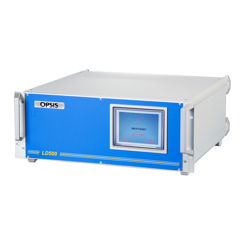
Opsis LD500 Installation & user guide
Salutron
Salutron ComBi D3 user manual
Applent Instruments
Applent Instruments AT5110 user guide

Campbell
Campbell CS140 product manual

PCE Health and Fitness
PCE Health and Fitness CMM 8 user manual
