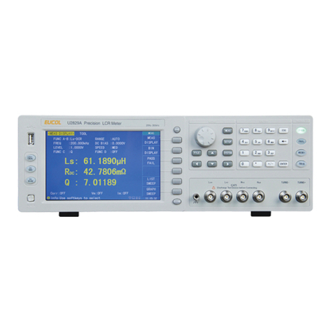
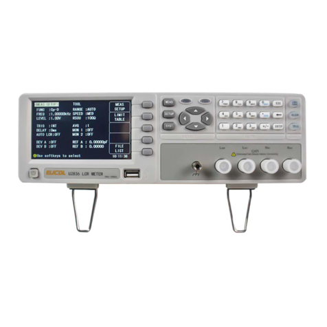
EUCOL U2810D User manual

OPERATION MANUAL
U2810D LCR Meter
EUCOL (CHANGZHOU) Electronic Technology Co., Ltd.
www.eucol.com.cn


CHAPTER 1 PREPARATION....................................................................................................................1-1
1.1 UNPACKING AND INSPECTION.................................................................................................................1-1
1.2 POWER REQUIREMENTS .........................................................................................................................1-1
1.3 FUSE SELECTION ....................................................................................................................................1-1
1.4 OPERATION ENVIRONMENT ....................................................................................................................1-2
1.5 USE TEST FIXTURE .................................................................................................................................1-2
1.6 WARM-UP AND CONTINUOUS WORKING TIME.......................................................................................1-2
1.7 OTHER FEATURES ...................................................................................................................................1-2
CHAPTER 2 PANEL DESCRIPTION.......................................................................................................2-3
2.1 ATOUR OF THE FRONT PANEL ...............................................................................................................2-3
2.2 ATOUR OF THE REAR PANEL .................................................................................................................2-6
2.3 DISPLAY AREA DEFINITION.....................................................................................................................2-7
CHAPTER 3 OPERATION.......................................................................................................................3-10
3.1 POWER ON............................................................................................................................................3-10
3.2 THE PRIMARY FUNCTION OPERATION .................................................................................................3-10
3.2.1 MEASUREMENT FUNCTION ................................................................................................................3-10
3.2.2 TEST FREQUENCY.............................................................................................................................. 3-11
3.2.3 TEST SIGNAL LEVEL........................................................................................................................... 3-11
3.2.4 MEASUREMENT SPEED......................................................................................................................3-12
3.2.5 EQUIVALENT CIRCUIT.........................................................................................................................3-12
3.2.5.1 Series and Parallel Circuit Setup.....................................................................................................3-12
3.2.5.2 How to Select the Measurement Circuit Mode ............................................................................... 3-12
3.2.6 SIGNAL SOURCE OUTPUT IMPEDANCE .............................................................................................3-13
3.2.7 MEASUREMENT RANGE .....................................................................................................................3-14
3.2.8 TRIG MODE.........................................................................................................................................3-14
3.2.9 CORRECTION......................................................................................................................................3-14
3.3 THE SECONDARY FUNCTION OPERATION............................................................................................3-17
3.3.1 BEEP FUNCTION.................................................................................................................................3-17
3.3.2 COMPARATOR FUNCTION...................................................................................................................3-17
3.3.2.1 Comparator Function ON/OFF .......................................................................................................3-18
3.3.2.2 Input the Low/High Limits..............................................................................................................3-18
3.3.3 PRIMARY PARAMETER DISPLAY MODE .............................................................................................3-20
3.3.4 AUTOMATIC IDENTIFICATION(AI)FUNCTION ......................................................................................3-21
CHAPTER 4 HANDLER INTERFACE ..................................................................................................4-22
4.1 INTRODUCTION ......................................................................................................................................4-22
4.2 OPERATION............................................................................................................................................4-22
4.2.1 SIGNAL DEFINITION ............................................................................................................................4-22
4.2.2 ELECTRICAL CHARACTERISTICS .......................................................................................................4-27
CHAPTER 5 RS232C SERIAL INTERFACE........................................................................................5-29
5.1 INTRODUCTION ......................................................................................................................................5-29
5.2 U2810D’S SERIAL INTERFACE.............................................................................................................5-29
5.3 COMMUNICATION WITH ACOMPUTER ..................................................................................................5-30

5.4 SERIAL PORT PARAMETER....................................................................................................................5-30
5.5 SOFTWARE PROTOCOL.........................................................................................................................5-30
CHAPTER 6 THE SPECIFICATIONS ....................................................................................................6-32
6.1 MEASUREMENT FUNCTIONS .................................................................................................................6-32
6.2 EQUIVALENT MEASUREMENT CIRCUIT.................................................................................................6-32
6.3 MEASUREMENT RANGE ........................................................................................................................6-33
6.4 TRIGGER MODE .....................................................................................................................................6-34
6.5 MEASUREMENT TERMINALS .................................................................................................................6-34
6.6 MEASUREMENT SPEED .........................................................................................................................6-34
6.7 BASIC ACCURACY .................................................................................................................................6-34
6.7.1 MAXIMUM AND MINIMUM VALUES USED FOR ACCURACY CALCULATION ........................................6-35
6.7.2 MEASUREMENT SPEED FACTOR KS ..................................................................................................6-35
6.7.3 MEASUREMENT VOLTAGE LEVEL FACTOR KV ...................................................................................6-35
6.7.4 MEASUREMENT FREQUENCY FACTOR KF .........................................................................................6-35
6.8 MEASUREMENT FREQUENCY................................................................................................................6-35
6.9 TEST SIGNAL LEVEL .............................................................................................................................6-36
6.10 OUTPUT IMPEDANCE...........................................................................................................................6-36
6.11 DISPLAY RANGE ..................................................................................................................................6-36
6.12 CORRECTION FUNCTION.....................................................................................................................6-36
6.13 COMPARATOR FUNCTION ...................................................................................................................6-36
6.14 RANGING MODE ..................................................................................................................................6-37
6.15 BEEP FUNCTION..................................................................................................................................6-37
6.16 RS232 INTERFACE..............................................................................................................................6-37
6.17 HANDLER INTERFACE ......................................................................................................................6-37

Warranty
This EUCOL instrument product is warranted against defects in material and workmanship
for a period of one year from the date of shipment. Other items such as test fixtures, test
cables are warranted for 90 days from the date of shipment. During the warranty period, we
will, at our option, either repair or replace products which prove to be defective.
For warranty service or repair, this product must be returned to a service facility designated
by EUCOL. Purchaser shall prepay shipping charges to EUCOL and EUCOL shall pay for
the return of the product to Buyer. However, Buyer shall pay all shipping charges, duties,
taxes, and any other charges for products returned to EUCOL from another country.
Limitation of Warranty
This warranty does not apply to defects resulting from improper or inadequate maintenance
and care by Buyer, Buyer-supplied software or interfacing, unauthorized modification or
misuse, operation outside of the environmental specifications for the product, or improper
site preparation or maintenance.
No other warranty is expressed or implied. EUCOL specially disclaims the implied
warranties of merchantability and fitness for a particular use.
EUCOL’s responsibility to repair or replace defective products is the sole and exclusive
remedy provided to the customer for breach of this warranty. EUCOL shall not be liable for
any direct, indirect, special, incidental, or consequential damages, whether based on
contract, tort, or any other legal theory.

Safety Precautions
The following safety precautions must be observed to avoid injury and prevent damage
to this product or any products connected to it. To avoid potential hazards, read the
operating information carefully before using the product and use this product only as
specified.
NOTE: This product complies with INSTALLATION CATEGORY I as well as
POLLUTION DEGREE 2. This product is an INDOOR USE product.
zGround the Instrument
Before operating the instrument, make sure the instrument chassis is grounded with the
3-pole power cable.
zDon’t operate in an explosive atmosphere
To prevent explosion or file, don’t operate the instrument in the presence of
inflammable gases or fumes.
zUse the proper fuse
Replace the broken fuse with the same type and rating for continuous protection
against fire hazard.
zKeep away from live circuits
Don’t remove the instrument covers when operating the instrument. Component
replacement and internal adjustment can only be done by qualified personnel. Don’t
replace components with the power cable connected. Dangerous voltage may remain
even after the power cable has been disconnected. Always remove the power cable
from the instrument and discharge circuits before touching them.

1-1
Chapter 1 Preparation
This chapter provides the information necessary for performing an incoming inspection and
setting up the instrument before operation.
1.1 Unpacking and Inspection
Thank you for purchasing and using our product. Inspect the shipping container for damage.
If the shipping container or cushioning material is damaged, it should be kept until the
contents of the shipment have been checked for completeness and the U2810D has been
checked mechanically and electrically. The contents of the shipment should be as listed in
the packing list. If the contents are incomplete, if there is mechanical damage or defect, if
the instrument does not work normally, notify our company or our local representative.
Keep the shipping container and packing material for future use such as returning for
re-calibration or service.
1.2 Power Requirements
(1) Voltage: 198 to 242 Vac,
(2) Frequency: 47.5 to 63 Hz
(3) Power: 20 VA maximum
(4) In accordance with internal safety standards, this instrument is equipped with a three-
wire power cable. When connected to an appropriate ac power outlet, this cable
grounds the instrument frame.
(5) The instrument is carefully designed in order to reduce the disturbance induced by AC
power supply, however, low noise environment is recommended. Sometimes a power
source filter is needed.
Warning: For protection from electrical shock, the power cable ground must not be
defeated. The power plug must be plugged into an outlet that provides a
protective earth ground connection.
1.3 Fuse Selection
The instrument has been equipped with the 500 mA fuse before leaving factory. Use only
fuses with the required current rating and of the specified type as replacements. Do not use
a mended fuse or short-circuit the fuse-holder in order to by-pass a blown fuse. Find out
what caused the fuse to blow!

1-2
1.4 Operation Environment
(1) The Please do not operate the instrument in places where there is dusty, vibrant, under
direct sunlight, or where there is corrosive air.
(2) In order to maintain good measurement accuracy, the U2810D must be operated under
the following environment conditions:
Temperature: 0°C ~ 40°C
Humidity: ≤75% RH at 40°C.
(3) The instrument is carefully designed in order to reduce the disturbance induced by AC
power supply, however, low noise environment is recommended. Sometimes a power
source filter is needed.
(4) Please store the instrument in the place where the temperature is between 5°C and
40°C, humidity is less than 85% RH. If the instrument will not be put in use for a time,
please have it properly packed with its original box or a similar box for storage.
(5) The instrument, especially the test leads, should be kept far away from strong
electromagnetic field to avoid interference with measuring precision.
1.5 Use Test Fixture
Original test fixture and test clip leads should be used in order to ensure correct and
accurate measuring results. At the same time, test fixture, test clip leads and pins of DUT
should be kept clean in order to connect well between DUT and test fixture. Test fixture and
test clip leads are connected to Hcur、Hpot、Lcur and Lpot 4 terminals on the front panel.
For DUT which has shield, please connect the shield to the ground terminal “ ” of the
instrument.
1.6 Warm-up and Continuous Working Time
Warm up the instrument for a minimum time of 15 minutes in order to ensure measuring
precision.
Continuous working time should be less than 16 hours.
1.7 Other features
(1) Power consumption:≤20VA
(2) Dimension(W*H*D):310mm*105mm*295mm
(3) Weight: about 3.5kg

2-3
Chapter 2 Panel Description
This chapter provides information including a tour of the front and rear panel and display
area definition, which will help you to quickly learn how to operate the U2810D.
2.1 A Tour of the Front Panel
Figure 2-1 shows the brief description of each key on the U2810D’s front panel.
(1) Brand and Model
Mark and model of instrument
(2) LCD
Display the measurement results and test conditions, etc.
(3) Comparator Indication
Display the comparator sorting results: NG, P1, P2, P3, and AUX.
(4) Power on/off
Power on/off switch. In the “ON” position all operating voltages are applied to the
instrument. In the “OFF” position NO operating voltages are applied to the instrument.
(5) Keys

2-4
Figure 2-2 Keybaord
a) PAR A key:
The primary function is the setup key of main test parameter.
The secondary function is the sorting limits setup key LIMIT.
b) PAR B key:
The primary function is the setup key of second test parameter.
The secondary function is the buzzer’s beep status setup key BEEP..
c) FREQ key:
The primary function is the setup key of test frequency.
The secondary function is the comparison function key COMP.
d) SHIFT key:
The primary function is the secondary function enable key.
The secondary function is the return the meter key LOCAL.
e) EQU key:
The primary function is the equivalent circuit setup key.
The secondary function is the main parameter display mode setup key DISP.
f) SPEED key:
The primary function is the setup key of measurement speed.
Under limit setup status, it is the up cursor key or increase key [▲].
g) LEVEL key:
The primary function is the setup key of test voltage level.

2-5
The second function is the automatic identification function key AI.
h) CLEAR key:
The primary function is the setup key of correction function.
Under input status, it is the exit key [ESC].
i) RANGE key:
The primary function is the setup key of range HOLD or AUTO.
Under limit status , it is the left cursor key [
▲
].
j) 30/100 key:
The primary function is signal source output impedance setup key.
Under limit setup status, it is the down cursor or decrease key [▼].
k) TRIG MODE key:
The primary function is the trig mode setup key.
Under limit status, it is the right cursor key [
▼
].
l) TRIGGER key:
The primary function is the trigger key.
Under input status, it is the [ENTER] key.
(6) Test Terminals
There are 4 test terminals used to connect a 4-terminal test fixture or test leads for
measuring the device under test.
HCUR:High current
HPOT:High potential
LPOT:Low potential
LCUR:Low current
(7) Frame Terminal
This is the frame terminal which is tied to the instrument’s chassis and which can be
used for measurements that require guarding.

2-6
2.2 A Tour of the Rear Panel
Figure 2-3 shows a brief description of the U2810D’s rear panel.
(1) Name Plate
Name plate is used to provide the information of date, model, lot number and
manufacturer etc.
(2) Line Input Receptacle and Fuse Holder
AC power cord receptacle.
(3) USB Device Interface
This is the USB device interface connector used when operating through the USB
interface.
(4) RS232C Interface
This is the RS232C interface connector used when operating through the serial
interface.
(5) Handler Interface
This is the HANDLER interface connector used when operating with a component
handler to fully automate component testing, sorting, and quality control data
processing. U2810D receives the Trigger signal and outputs the comparison results
through the HANDLER interface.

2-7
2.3 Display Area Definition
Figure 2-4 shows the display area definition of the U2810D LCD screen.
Figure 2-4 Display Area Definition
(1) Test Signal Frequency Indication
“100 Hz” is on:The current test signal frequency is 100 Hz.
“120 Hz” is on:The current test signal frequency is 120 Hz.
“1 kHz” is on:The current test signal frequency is 1 kHz.
“10 kHz” is on:The current test signal frequency is 10 kHz.
(2) Test Signal Level Indication
“0.1 V” is on:The current test signal voltage is 0.1 V.
“0.3 V” is on:The current test signal voltage is 0.3 V.
“1.0 V” is on:The current test signal voltage is 1.0 V.
(3) Signal Source Output Impedance Indication
“30Ω” is on:Signal source output impedance is 30 Ω.
“100Ω” is on:Signal source output impedance is 100 Ω.
(4) Measurement Speed Indication
“Fast” is on: Fast measurement speed
“Med” is on: Medium measurement speed
“Slow” is on: Slow measurement speed
(5) Range Indication
Indicate the current ranging mode and the current range number.
“Auto” is on:Range AUTO

2-8
“Hold” is off:Range HOLD
(6) Trigger Mode Indication
“Int” is on: Internal trigger mode
“Man” is on:Manual trigger mode
“Ext” is on: External trigger mode
“Dut” is on: DUT trigger mode
“Bus” is on: Bus trigger mode
(7) Equivalent Circuit Mode Indication
“” is on:Series equivalent circuit mode.
“ ” is on: Parallel equivalent circuit mode.
(8) Auto Identification Mode Indication
“” is on: Starts auto identification mode.
“” is off: Stops auto identification mode.
(9) Display Mode of The Primary Parameter Indication
Indicate the current primary parameter display mode.
“” is off: Direct reading display mode.
“” is on: Percent deviation display mode.
(10) The primary Parameter Indication
Indicate the current measuring primary parameter user selected.
“L:” is on:Inductance is measured and displayed.
“C:” is on:Capacitance is measured and displayed.
“R:” is on:Resistance is measured and displayed.
“Z:” is on:Impedance is measured and displayed.
(11) The Primary Parameter Display
Display the current measurement result of the primary parameter.
(12) Unit of The primary Parameter Indication
Indicate the current unit of measurement result of the primary parameter.
Unit of inductance:μH, mH, H.
Unit of capacitance:pF, nF, μF, mF.
Unit of resistance/impedance:Ω, kΩ, MΩ.
(13) Unit of The second Parameter Indication
Indicate the current unit of measurement result of the second parameter.
Unit of phase angle:Rad、Deg.
Unit of reactance / equivalent series resistance:mΩ,Ω,kΩ,MΩ.

2-9
(14) The Secondary Parameter Display
Display the current measurement result of the secondary parameter.
(15) The Secondary Parameter Indication
Indicate the current measuring secondary parameter user selected.
(16) The Secondary Function Indication
“ ” is on: The current key function is the secondary function.
“” is off: The current key function is the primary function.
(17) Comparator Function Indication
“” is on: The comparator function is turned on.
“” is off: The comparator function is turned off.
(18) Alarm Indication
“”is on: Alarm buzzer is turned on.
“”is off: Alarm buzzer is turned off.
(19) Remote Control Indication
“” is on:Host in the remote control state,keyboard(except LOCAL) locked
“” is off:Host in local state.

3-10
Chapter 3 Operation
3.1 Power On
1) Press power switch to turn on the instrument.
2) Version number of the instrument is first displayed on the LCD screen.
3) The instrument enters the measurement status after a short delay. Figure 3.1
shows the information displayed in measurement status. It maybe different with the
actual display due to different measurement setup.
3.2 The Primary Function Operation
3.2.1 Measurement Function
U2810D measures two components of the complex impedance parameters at the same
time in a measurement cycle. The primary and secondary measurement parameters are
listed as follows.
Primary Parameter
L: Inductance
C: Capacitance
R: Resistance
|Z|: Absolute value of impedance
Secondary Parameter
D: Dissipation factor
Q: Quality factor
θ: Phase angle
X : Reactance
ESR: Equivalent series resistance
|Z| is the absolute value of impedance, so it is always a positive value; While L/ C/ R maybe
a positive value or sometimes a negative value.

3-11
When measurement function is C-D and the primary parameter measurement result is
negative, this means the component under test is probably an inductor.
When measurement function is L-Q and the primary parameter measurement result is
negative, this means the component under test is probably a capacitor.
When measurement function is R-Q and the measurement result of resistor is negative, this
is due to over zero correction, please perform open and short correction correctly.
U2810D provides 4 combinations of primary and secondary parameters:
L-Q
C-D
R-X
Z-θ
Perform the following steps to set the measurement function.
1. Assume that current measurement function is L-Q. Primary parameter indication is “L”,
secondary parameter indication is “Q”.
2. Press PAR A key, measurement function is changed to C-D. Primary parameter
indication is “C”, secondary parameter indication is “D”.
3. Press PAR A key, measurement function is changed to R-X. Primary parameter
indication is “R”, secondary parameter indication is “X”.
4. Press PAR A key, measurement function is changed to Z-θ. Primary parameter
indication is “Z”, secondary parameter indication is “θ”.
5. Keep on pressing PAR A key, until the measurement function required is indicated.
6. Keep on pressing PAR B key, until the secondary parameter required is indicated.
3.2.2 Test Frequency
U2810D provides 4 typical frequency points:100Hz, 120Hz, 1kHz and 10kHz. The current
test frequency is displayed on the LCD.
Perform the following steps to set the test frequency.
1. Assume the current test frequency of the instrument is 100Hz. “100Hz” is indicated on
the LCD.
2. Press FREQ key, test frequency is changed to 120 Hz, and “120Hz” is indicated on the
LCD.
3. Keep on pressing FREQ key, until the test frequency required is indicated on the LCD.
3.2.3 Test Signal Level
U2810D provides 3 kinds of test signal voltage levels: 0.1VRMS, 0.3 VRMS and 1.0 VRMS.
Perform the following steps to set the test signal level.
1. Assume the current test signal level 1.0V, and “1.0V” indicated on the bottom of LCD.

3-12
2. Press LEVEL key, test signal level is changed to 0.1V, and “0.1V” is indicated on the
LCD.
3. Press LEVEL key, test signal level is changed to 0.3V, and “0.3V” is indicated on the
LCD.
4. Press LEVEL key, test signal level is changed back to 1.0V, and “1.0V” is indicated on
the LCD.
5. Keep on pressing LEVEL key, until the test signal level required is indicated on the
LCD.
3.2.4 Measurement Speed
U2810D provides 3 kinds of measurement speeds: Fast, Med and Slow. Generally, a slow
measurement speed will result in more stable and accurate measurement results.
Fast: 20 meas/sec
Med: 7 meas/sec
Slow: 3 meas/sec
Perform the following steps to set the measurement speed
1. Assume the current measurement speed is FAST, and “FAST” is indicated on the LCD.
2. Press SPEED key, the measurement speed is changed to MED, and “MED” is indicated
on the LCD.
3. Press SPEED key, the measurement speed is changed to SLOW, and “SLOW” is
indicated on the LCD.
4. Press SPEED key, the measurement speed is changed back to FAST, and “FAST” is
indicated on the LCD.
5. Keep on pressing SPEED key, until the measurement speed required is indicated on
the LCD.
3.2.5 Equivalent Circuit
3.2.5.1 Series and Parallel Circuit Setup
U2810D provides the series and parallel equivalent circuit modes for measuring the L, C,
and R.
Perform the following steps to set the equivalent circuit mode
1. Press EQU key to switch between the series mode and parallel mode, and the current
equivalent circuit mode is displayed on the bottom of LCD.
3.2.5.2 How to Select the Measurement Circuit Mode
Guide lines for selecting the capacitance measurement circuit mode.
Small capacitance yields large reactance, which implies that the effect of the parallel
resistance has relatively more significance than that of series resistance. The low value

3-13
of the series resistance has negligible significance compared with the large capacitive
reactance, so the parallel circuit mode should be used.
Large capacitance yields small reactance, which implies that the effect of the series
resistance has relatively more significance than that of parallel resistance. The large
value of the parallel resistance has negligible significance compared with the low
capacitive reactance, so the series circuit mode should be used.
The following is a rule of thumb for selecting the circuit mode according to the
impedance of the capacitor.
Above approx. 10kΩ: use parallel circuit mode
Below approx. 10Ω: use series circuit mode
Between above values: follow the manufacturer’s recommendation
Guide lines for selecting the inductance measurement circuit mode.
The reactance of a large inductance at a given frequency is relatively large (compared
with that of a small inductance), so the parallel resistance becomes more significant
than the series component. So, a measurement in the parallel equivalent circuit mode
is more suitable.
Conversely, for low values of inductance the reactance becomes relatively small
(compared with that of a large inductance), so the series resistance component is more
significant. So, the series equivalent circuit mode is the appropriate choice.
The following is a rule of thumb for selecting the circuit mode according to the
impedance of the inductor.
Below approx. 10Ω: use series circuit mode
Above approx. 10kΩ: use parallel circuit mode
Between above values: follow the manufacturer’s recommendation
3.2.6 Signal Source Output Impedance
U2810D provides two different signal output impedance 30Ωand 100Ω. The measurement
current through the DUT will be different with different signal output impedance under the
test same signal voltage level. The current sensitive components, for example the inductors
with cores, will get different measurement results under different signal source output
impedance. In order to be compatible with other well-known instruments in the world, use
the same signal source output impedance for each instrument.
Perform the following steps to set the signal source output impedance
1. If “100Ω” is displayed on the LCD, this means the current signal source output
impedance is 100Ω.
2. Press 30/100 key to set the current source output impedance to 30Ω, and “30Ω” will be

3-14
displayed on the LCD.
3. Repeat step 2 and 3, signal source output impedance will be switched between 30Ω
and 100Ω.
3.2.7 Measurement Range
Perform the following steps to set the measurement range
1. Assume the current measurement range is set to “Auto” status. Press RANGE key to
change the measurement range from the “Auto” mode to the “Hold” mode. When the
measurement range is set to the “Hold” mode, “Auto” is turned off from the LCD, the
impedance range is fixed at the current range setting.
3.2.8 Trig Mode
U2810D provides 4 kinds of trig modes:
INT : Internal trigger mode
MAN: Manual trigger mode
EXT : External trigger mode
DUT : DUT trigger mode
BUS: BUS trigger mode
Performing the following steps to set the measurement mode:
1. Press TRIG MODE key to switch trig mode from INT to BUS, and the current
measurement mode will be displayed on LCD.
Note: when the DUT mode is selected, the nominal value of primary parameter should be
entered.
3.2.9 Correction
U2810D’s OPEN correction capability cancels errors due to the stray admittance (G, B) in
parallel with the device under. U2810D’s SHORT correction capability corrects for the
residual impedance (R, X) in serial with the device under test.
Perform following steps for the open and short correction:
1. When the U2810D is under the measurement status, Press CLEAR key to enter the
correction function.
2. If the fixture is open, the information shown in Figure 3-2 will be displayed.
Table of contents
Other EUCOL Measuring Instrument manuals
Popular Measuring Instrument manuals by other brands

Axioma
Axioma QALCOSONIC F1 Technical description, installation and user instructions
Kailiu Instrument
Kailiu Instrument MGG/KL-DCB Operation manual
SPM
SPM intellinova compact INS06 Ex Assembly, installation and operation instructions
YOKOGAWA
YOKOGAWA Power Series Plus instruction manual
OSD Audio
OSD Audio SD-W10 user guide
Twinno
Twinno T4030 operating manual

