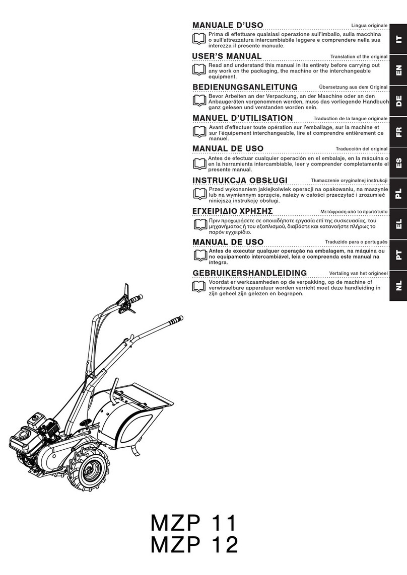
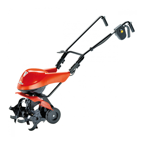
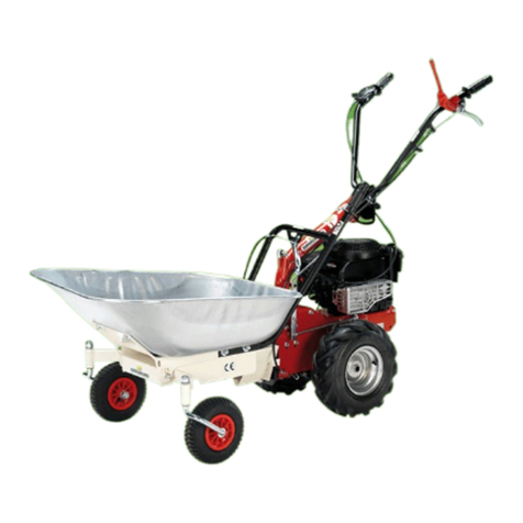
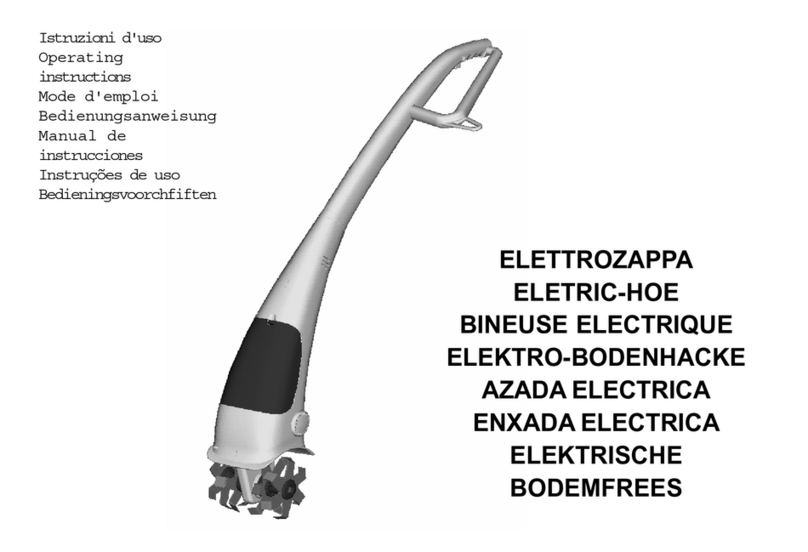
Euro Systems P55 User manual

Istruzioni d’uso
Operating Instructions
Mode d’emploi
Bedienungsanweisung
Bedieningsvoorschriften
Instruções de uso
Instrucciones para la utilización
O Δ Η Γ Ι Ε Σ Χ Ρ Η Σ Η Σ
Руководство по эксплуатации
Instrukcja obsługi MOTOCOLTIVATORE
MOTOR-CULTIVATOR
MOTOCULTEUR
MEHRZWECKGERÄT
CULTIVATOR
MOTOCULTOR
MOTOCULTIVADOR
Μ Ο Ν Ο Α Ξ Ο Ν I Κ Ο
МОТОКУЛЬТИВАТОР
GLEBOGRYZARKA SPALINOWA

1 2
3 4
1
2
3

A
B
5 6a
13
1 32
13
14
15
14
14
14
13

7
6b
1 32
14
13
14
13
14
15
14
13
4
3
1
2

8 9 10
11 12 13

14 15 16
17 18

Leggere il manuale prima di usare la macchina.
Read the instructions manual before operating on the
machine.
Lire le mode d’emploi avant l’usage.
Lesen Sie die Gebrauchsanweisung vor der
Inbetriebnahme.
Lees de handleiding voor het gebruik.
Ler o manual das instruções antes do uso.
Antes de proceder a montar la màquina lea atentamente
estas instrucciones.
Διαβάστε τις οδηγίες χρήσης πριν θέσετε το μηχάνημα
σε λειτουργία.
Перед началом эксплуатации культиватора
ознакомьтесь с настоящим руководством.
Przed użyciem maszyny przeczytać instrukcje obsługi.
Attenzione: rotazione fresa
Danger tiller rotation
Attention: danger rotation fraise
Achtung: drehende Hackwerkzeuge
Let op: draaiende frees
Atenção: rotação da fresa
Atencion: la fresa gira
Κίνδυνος περιστροφής της ρέζας
Опасность травмирования
вращающейся фрезой
Niebezpieczeństwo wirujących noży
Etichetta acceleratore
Label accelerator
Plaquette acceleration
Aufkleber - Gashebel
Etiket gaspedaal
Etiqueta do acelerador
Etiqueta acelerador
Ετικέτα εκκίνησης
Управление дроссельной
заслонкой
Tabliczka przyspieszenia
Attenzione: rotazione lama
Danger : rotation blade
Attention: danger rotation lame
Achtung: Messerrotation
Let op: draaiend mes
Atenção: rotação da lâmina
Atención, rotación hoja
Опасность травмирования ножами
Niebezpieczeństwo wirujących ostrzy
Innesto marcia
Speed clutching
Embrayage marche
Gang-Einschaltung
Inschakeling versnelling
Engate de velocidade
Conección marcha
Μπροστινή κίνηση
Переключение скоростей
Sprzęgło biegu

Innesto attrezzo
Cutter bar clutching
Embrayage barre
Mähbalkenantrieb
Maaibalkaandrijving
Engate da alfaia
Conección utensilios
Συμπλέκτης μπάρας κοπής
Фиксация ножевого бруса
Sprzęgło urządzenia
Indice marce
Speed index
Index marches
Angabe
Aanduiding versnellingen
Indice de velocidades
Índice marchas
Δείκτης ταχύτητας
Расположение передач
Wskaźnik położenia biegów
1
Costruttore
Manufacturer
Constructeur
Hersteller
Fabrikant
Fabricante
Constructor
Κατασκευαστής
Производитель
Producent
2
Modello
Type
Modèle
Modell
Model
Modelo
Modelo
Τύπος/ μοντέλο
Модель
Model
4
Numero di serie articolo – Progressivo
Numéro de série article - Progressif
Serial number - Progressive
Serienummer - fortlaufend
Serienummer artikel - Progressief
Numero de série - Progressivo
Número de serie artículo – Progresivo
Αριθμός σειράς / πλαισίου – Αυξανόμενο
Серийный номер (порядковый)
Numer seryjny – kolejny
6
Potenza in kW
Puissance en kW
Power in kW
Leistung in kW
Vermogen in kW
Potência em kW
Potencia en kW
Ισχύς σε kW
Мощность, кВт
Moc w kW
3
Anno di costruzione
Année de construction
Year of construction
Baujahr
Bouwjaar
Ano de fabricação
Año de construcción
Έτος κατασκευής
Год изготовления
Rok produkcji
5
Massa
Masse
Mass
Gewicht
Gewicht
Massa
Masa
Βάρος
Вес
Masa

Indice
Introduzione
Condizioni di utilizzazione
Suggerimenti di sicurezza
Istruzioni d’ uso
Trasporto
Montaggio
Regolazione
Manutenzione
Dati tecnici
Rumore aereo
Guasti
Pericolo grave per
l’incolumità dell’operatore
e delle persone esposte.
INTRODUZIONE
Gentile cliente, lei ha acquistato una nuova attrezzatura. La ringraziamo per la ducia accordata ai ns.
prodotti e le auguriamo un piacevole utilizzo della sua macchina.
Abbiamo creato queste istruzioni per I’uso allo scopo di assicurare, n dall’inizio, un funzionamento privo
d’inconvenienti. Seguite attentamente questi consigli, avrete la soddisfazione di possedere per molto tempo
una macchina che funziona a dovere.
Le nostre macchine, prima di essere fabbricate in serie, vengono collaudate in maniera molto rigorosa e, durante
la fabbricazione vera e propria, sono sottoposte e severi controlli. Ciò costituisce, per noi e per voi, la migliore
garanzia che si tratta di un prodotto di riprovata qualità.
Questa macchina é stata sottoposta a rigorosi test neutrali, nel paese d’origine, e risponde alle norme
di sicurezza in vigore.
Per garantire questo, é necessario utilizzare esclusivamente ricambi originali.
L’utilizzatore perde ogni diritto di garanzia qualora vengono utilizzati ricambi non originali.
Con riserva di variazioni tecnico-costruttive. Per informazioni e per ordinazioni di pezzi di ricambio si prega
citare il numero di articolo e il numero di produzione.
nDATI PER L’IDENTIFICAZIONE (FIG. 1) L’etichetta con i dati della macchina e il numero
di matricola è sul anco sinistro del motocoltivatore, sotto il motore (g.1). Nota - Nelle eventuali richieste
di Assistenza Tecnica o nelle ordinazioni delle Parti di Ricambio, citare sempre il numero di matricola del
motocoltivatore interessato.
nCONDIZIONI DI UTILIZZAZIONE - LIMITI DUSO
Il motocoltivatore è progettato e costruito per eseguire operazioni di zappatura o falciatura di terreni erbosi
e deve lavorare esclusivamente con attrezzi e con ricambi originali. Ogni utilizzo diverso da quello sopra
descritto è illegale; comporta, oltre al decadimento della garanzia, anche un grave pericolo per l’operatore e
per le persone esposte.
n NORME DI SICUREZZA
Attenzione: prima del montaggio e la messa in funzione leggere attentamente il libretto istruzione. Le
persone che non conoscono le norme di utilizzazione non possono usare la macchina.
1. L’ uso della macchine è vietato ai minori di 16 anni e alle persone che hanno assunto alcol, medicine
o droghe.
2. La macchina è stata progettata per essere utilizzata da un solo operatore addestrato. L’utilizzatore
dell’apparecchio è responsabile di danni arrecati ad altre persone ed alle loro proprietà; controllare
che altre persone, sopratutto i bambini stiano lontani dalla zona di lavoro (10 mt.).
3. Togliere corpi estranei dal prato prima di iniziare il lavoro. 1
ITALIANO
Istruzioni d’uso originali

4. Non mettere in moto la macchina quando si è davanti alle frese o alla barra falciante. Tirando la funicella di avviamento del motore le frese
o la barra falciante non devono mettersi in moto. (Se accade intervenire sul rispettivo registro di regolazione).
5. Durante il lavoro, per maggiore protezione, vanno indossate protezioni acustiche (cufe e/o tappi), calzature antinfortunistiche e pantaloni
lunghi.
6. Per trasportare la macchina fermare il motore.
7. Tutte le operazioni di servizio devono essere effettuate con motore spento.
8. Non abbandonare la macchina con motore in moto.
9. Il conduttore deve operare impugnando il manubrio.
10. In caso di urto contro un ostacolo, che blocchi la macchina, farla controllare da una stazione di servizio.
11. E’ vietato avviare la macchina in locali chiusi .
12. AVVERTENZA La benzina è altamente inammabile, conservare il carburante in appositi recipienti. Non fare il pieno di benzina in locali
chiusi né con il motore in moto. Non fumare e fare attenzione alle fuoriuscite di combustibile dal serbatoio. In caso di fuoriuscita non tentare
di avviare il motore, ma allontanare la macchina dall’area interessata evitando di creare fonti di accensione nché non si sono dissipati i
vapori della benzina. Rimettere a posto correttamente i tappi del serbatoio e del contenitore della benzina. Non aprire il tappo della benzina
con motore acceso o quando è caldo.
13. Attenzione al tubo di scarico. Le parti vicine possono arrivare a 80°.
14. Facciamo presente che non ci assumiamo nessuna responsabilità per danni dovuti a: a) riparazioni effettuate da personale non specializzato o
da centri di assistenza non autorizzati, oppure b) impiego di RICAMBI NON ORIGINALI. Per gli accessori si applicano le stesse condizioni.
nISTRUZIONI D’USO
nISTRUZIONI - MOTORE Leggete attentamente le istruzioni allegate relative al motore.
nMESSA IN MOTO Attenzione: portare entrambi le leve di azionamento nella posizione “0”. Portare l’acceleratore su posizione “Start”.
Tirare leggermente la funicella di avviamento no a che il motore oppone una certa resistenza, dopodiché lasciare riavvolgere la funicella completamente
e poi tirare con energia no ad una completa corsa del braccio. Per spegnere Portare la leva comando su posiz. STOP.
nDISPOSITIVO DI SICUREZZA —Tutti i motocoltivatori sono dotati di dispositivo antinfortunistico. Detto dispositivo causa il disinnesto
automatico della trazione quando si rilascia la relativa leva di comando.
n TRASPORTO Per la movimentazione è previsto l’uso di carrello elevatore. Le forche, allargate al massimo consentito, vanno inserite negli
appositi spazi del pallet. La massa della macchina è indicata nella etichetta della marcatura e riportata nei dati tecnici.
n MONTAGGIO DEL MOTOCOLTIVATORE Il motocoltivatore viene consegnato a destinazione, salvo accordi diversi, smontato e sistemato
in un adeguato imballaggio. Per completare il montaggio del motocoltivatore osservare la seguente procedura.
n MONTAGGIO MANUBRIO (Fig. 2): Fissare il manubrio (g. 2, part. 1) al supporto (2) per mezzo delle viti (3). Attenzione: le rondelle
con diametro maggiore devono essere montate in corrispondenza delle asole. Regolare l’altezza del manubrio agendo sulle viti (3) che lo ssano.
Posizionare l’asta cambio marce (4) facendola passare attraverso la guida (5) ed inlare l’estremità nel foro dello snodo (6) e bloccare con la spilla
ad R (7).
ITALIANO
2

nMONTAGGIO CAVO ACCELERATORE (Fig. 3) (con guaina metallica) Posizionare, a fondo corsa, la leva (g. 3 particolare 1)
installata sul motore come indicato dalla freccia “A,, in gura. Portare a ne corsa il manettino comando acceleratore (2) installato sulla stegola come
indicato dalla freccia “B,, in gura. Inserire il cavo (3) nel foro (4), ssare la guaina (5) con l’apposito cavallotto (6) e bloccare con la vite (7). Il cavo
acceleratore deve essere ssato al motore dal lato candela. Attenzione: il manettino acceleratore in posizione “stop’, deve spegnere il motore.
nCAVO COMANDO TENDICINGHIA (Fig. 4) Il cavo di comando (1) è già collegato alla leva tendicinghia del telaio ed alla leva (2).
Fissare la leva (2) sul manubrio tramite la vite (3) presente nella busta accessori.
nMONTAGGIO ACCESSORI (Fig. 5) Il Il motocoltivatore è provvisto di un attacco rapido per gli accessori. Montare la cinghia sulla puleggia
superiore A con i seguenti accessori : tosaerba falciatutto e fresa. Montare la cinghia sulla puleggia inferiore B con i seguenti accessori: spazzola e
barra falciante.
nMONTAGGIO BARRA FALCIANTE (Fig. 6a) A motore fermo e con la macchina in posizione orizzontale, inserire per metà il perno della
barra (1) nella sua sede (2). Montare la cinghia (3) sulla rispettiva puleggia portando in ne corsa il perno guida. Posizione 1 e 2: ruotare la maniglia
(13) no ad agganciare la molla (14) all’attacco (15). Posizione 2 e 3: per completare l’aggancio ruotare la maniglia (13) in senso inverso no a mettere
in tensione la molla (14). Montare il cofano (6) tramite il perno di centraggio (7) e il perno lettato (8). Serrare il dado e relativa rondella sul cofano.
n MONTAGGIO FRESA (g. 6b): A motore fermo e con la macchina in posizione orizzontale, inserire per metà il perno della fresa (1) nella sua
sede (2). Montare la cinghia (3) sulla rispettiva puleggia portando in ne corsa il perno (1). Posizione 1 e 2: ruotare la maniglia (13) no ad agganciare
la molla (14) nell’asola (15). Posizione 2 e 3: per completare l’aggancio ruotare la maniglia (13) in senso inverso no a mettere in tensione la molla (14).
Montare il coperchio (6) tramite la vite di centraggio (7); la leva impedimento retromarcia (8) si posiziona correttamente rispetto alla leva cambio marce
(9). Serrare il dado e relativa rondella sul coperchio (6).
nMONTAGGIO ASTA RINVIO CAMBIO (Fig. 12) Inserire l’estremità dell’asta (2) nel foro della leva (3), quindi bloccare con la spina
ad “R”.
n REGISTRAZIONE DELLA CINGHIA MOVIMENTO ACCESSORI (g.7): Per aumentare la tensione della cinghia tra macchina
e attrezzo, occorre intervenire sul registro (2) in modo che l’accessorio inizi a lavorare solo quando la leva di comando ha superato metà della propria
corsa (g. 7).
Nel caso della barra falciante, per aumentare la tensione delle due cinghie inferiori del movimento barra, occorre svitare il dado (9) e togliere i
distanziali tra le semipulegge (g.5).
Nel caso della fresa, dopo 2 ore di lavoro controllare la tensione della cinghia (3, g.6).
nREGISTRAZIONE DEL COMANDO TENDICINGHIA (Fig. 8) Attenzione - Le ruote devono iniziare a girare solo quando la leva
di comando ha superato la metà della propria corsa. Quando la leva è completamente tirata (posizione di lavoro), la molla di carico del tendicinghia
(part. 2) si deve allungare di circa 6 - 8 mm. Per ottenere le condizioni sopracitata occorre agire sul registro (1) installato nelle vicinanze del comando
tendicinghia.
ITALIANO
3

nINNESTO DEL MOVIMENTO DELLA BARRA FALCIANTE (Fig. 7) Sganciare la levetta di sicurezza (3), quindi abbassare la
leva innesto attrezzo (4).
n REGOLAZIONE DEL MANUBRIO : Il manubrio del motocoltivatore è orientabile sia lateralmente sia in altezza. E’ consigliabile, prima di
iniziare qualsiasi tipo di lavoro, regolare il manubrio alle esigenze dell’operatore per rendere il motocoltivatore facilmente manovrabile in ogni movimento.
L’orientamento laterale del manubrio permette all’operatore di non calpestare il terreno già lavorato e di non danneggiare la vegetazione.
n REGOLAZIONE LATERALE DEL MANUBRIO (g. 2): La regolazione laterale del manubrio si può ottenere su 3 diverse posizioni
sia quando si lavora con attrezzi posteriori (operazioni tipo fresatura) che quando si lavora con attrezzi frontali (operazioni tipo falciatura) agendo nel
modo seguente:
Ruotare in senso antiorario la leva (8) per disinserire il bloccaggio. Regolare il manubrio nella posizione desiderata. Bloccare nuovamente il manubrio
ruotando la leva (8) in senso orario e accertarsi che i denti siano perfettamente innestati.
La rotazione del manubrio di 180° deve avvenire in senso orario per evitare danni ai cavi che scendono lungo il piantone: è necessario, inoltre,
staccare l’asta cambio marce (4) per poi riposizionarla a rotazione avvenuta.
Effettuando la rotazione del manubrio di 180° le posizioni delle marce al cambio risultano invertite, cioè la retromarcia diventa marcia avanti e
viceversa.
n REGOLAZIONE DEL MANUBRIO IN ALTEZZA (g. 2): 1) Allentare le viti (3), regolare il manubrio all’altezza voluta. 2) Bloccare
le viti (3).
nREGOLAZIONE ALTEZZA BARRA FALCIANTE (Fig. 9) Regolare l’altezza di taglio secondo le esigenze e le difcoltà del terreno,
tramite i pattini di regolazione. Operare nel seguente modo: Allentare il dado (1), portare il pattino (2) nella posizione desiderata, serrare i dadi (1).
Eseguire l’operazione su entrambi i pattini.
n REGOLAZIONE DELLA LAMA (Fig. 10) Dopo la sostituzione di una lama o dopo alcune ore di lavoro, è necessaria la regolazione
dei premilama tramite le viti (1) e il loro controdado. IMPORTANTE Per il controllo di ogni regolazione si deve dapprima smontare il cofano poi
fare ruotare lentamente con la mano la puleggia (2) e vericare che le lame si muovano liberamente.
n REGOLAZIONE DEL TIMONE (g. 11): Per ottenere una buona fresatura e un avanzamento regolare del motocoltivatore, l’attrezzo
- fresa è dotato di un timone (1) che regola la profondità di lavoro delle zappette. Tirando indietro la leva comando timone (2) e muovendo la stessa
in alto o in basso, si controlla la penetrazione nel terreno: la regolazione è corretta quando la macchina avanza con velocità costante senza balzi (in
tal caso muovere la leva verso la posizione B) o affossamenti della ruota e della fresa (in tal caso muovere la leva verso la posizione A).
FRESATURA DI TERRENI DURI: portare il timone nella posizione (B). Questa posizione corrisponde ad una scarsa profondità di lavorazione.
FRESATURA DI TERRENI MORBIDI: Portare il timone nella posizione (A). Questa posizione corrisponde ad una grande profondità di lavorazione.
Effettuare l’accensione del motore con il timone nella posizione (B), in questo modo si evita alle zappette di scalre la supercie.
ITALIANO
4

nRIMESSAGGIO E MANUTENZIONE PERIODICA Mantenere serrati tutti i dadi, i bulloni e le viti per garantire il funzionamento della
macchina nelle condizioni di sicurezza. Lasciar raffreddare la macchina prima di immagazzinarla e comunque non riporla con benzina nel serbatoio
all’interno di un edicio, dove i vapori possono raggiungere una amma libera o una scintilla. Svuotare il serbatoio all’esterno. Per ridurre il pericolo
di incendio mantenere il motore, il silenziatore e la zona di immagazzinamento della benzina liberi da foglie, erba e grasso in eccesso.
SCATOLA CAMBIO (g. 12-13): Lubricante: usare olio SAE 80. Quantità d’olio indicativa: 0,40 litri. Per vericare il livello: mettere la macchina in
piano. Svitare il tappo (1, g. 12)e controllare che l’olio sia a livello inferiore del foro. Il tappo di riempimento corrisponde al livello olio. Controllare il
livello ogni 60 ore di lavoro.
Per sostituire l’olio: lo scarico dell’olio si effettua togliendo il tappo (1, g. 12) ed inclinando il motocoltivatore.
Lo scarico dell’olio deve essere effettuato a macchina calda. A scarico ultimato inclinare la macchina, rifornire con olio nuovo no al livello inferiore
del foro e avvitare il tappo (1, g. 12). Svitare il tappo (2, g. 13) e rifornire la scatola cambio con olio nuovo no al livello inferiore del foro, tenendo
inclinata la macchina. Avvitare il tappo. Sostituire l’olio ogni 150 ore di lavoro.
IMPORTANTE! Per evitare l’inquinamento delle falde acquifere, l’olio esausto non deve essere gettato in scarichi fognari o canali idrici. Depositi
per l’olio esausto sono ubicati presso tutti i distributori di benzina, oppure in discariche autorizzate secondo le normative comunali del Comune di
residenza.
SEDE ATTACCO ATTREZZO (Fig. 14) Dopo ogni uso pulire ed ingrassare la sede (2) attraverso l’ingrassatore (1).
MANUTENZIONE DELLA BARRA FALCIANTE La barra falciante richiede una buona e frequente manutenzione. Il lavaggio e la pulizia della lama
è considerato indispensabile dopo ogni suo utilizzo. Quando la macchina non viene usata per lunghi periodi è indispensabile proteggere la barra e la
lama con sostanze anticorrosive e antiossidanti.
SOSTITUZIONE DELLA LAMA FALCIANTE (Fig. 15) Lo smontaggio della lama superiore per l’aflatura o la sostituzione avviene svitando le viti
(1) e slando la lama tramite un perno inlato nel foro (2). Dopo 2 o 3 aflature è consigliata la sostituzione della lama. La lama inferiore si consiglia
di sostituirla, in base all’usura, dopo un paio di cambi di quella superiore. Contemporaneamente si sostituiscono i premilama in plastica (3).
AFFILATURA DELLA LAMA (Fig. 16) In relazione alla intensità di lavoro la lama deve essere periodicamente aflata. Si consiglia non oltre le 15
ore di lavoro. A questo scopo la lama viene rimossa e ben ripulita. Deve essere vericato che i denti e le controlame non siano deformati, dopo di
chè si può procedere all’aflatura. Generalmente viene utilizzato un aflatore manuale con ca. 15000 - 20000 g/min., con punta aflante a testa piena
di diametro 25 mm. e lunghezza ca. 35 mm. I denti della barra necessitano un angolo di aflatura di 35° - 40°.
MANUTENZIONE DELLA FRESA (Fig. 17): Ogni qualvolta si usa la fresa, è necessario che l’operatore verichi: a) che le viti e i dadi di ssaggio
della stella destra e sinistra all’albero fresa siano serrati a fondo; b) che tutte le viti ed i dadi di ssaggio delle zappette siano serrati a fondo. Ogni 60
ore vericare il livello dell’olio nella scatola, svitando il tappo (1, g. 17). L’olio deve risultare al livello inferiore del foro. Sostituire l’olio ogni 150 ore
di lavoro. Lo scarico lo si effettua togliendo il tappo (1) ed inclinando la fresa. Lo scarico dell’olio deve essere effettuato a macchina calda. A scarico
ultimato rifornire con olio nuovo no al livello inferiore del foro. Avvitare, poi, il tappo. Usare olio SAE 80.
nDESCRIZIONE (Fig. 18) 1) Leva comando Start.-Stop - 2) Leva comando della trasmissione ruote motrici - 3) Leva comando innesto attrezzo
- 4) Motore - 5) Leva regolazione manubrio laterale - 6) Asta comando marce.
ITALIANO
5

n DATI TECNICI
MOTOCOLTIVATORE CON BARRA FALCIANTE MOTOCOLTIVATORE CON FRESA
Larghezza di falciatura 870 mm Larghezza di fresatura 500 mm
Lunghezza con barra falciante 1500 mm Lunghezza max con fresa 1400 mm
Altezza 1000 mm Altezza 1000 mm
Massa 65 Kg. Massa 78 Kg.
Scartamento 430 mm Scartamento 430 mm
Pneumatici 2 ruote pneumatiche 13x5.00-6 Pneumatici 2 ruote pn. 13x5.00-6
Battiti della barra falciante 1300/ 1’ Rotazione dell’albero porta fresa 275 giri/ 1’
Velocità in operazione di falciatura: Velocità in operazione di fresatura:
Marcia avanti “1” 2,2 km/h Marcia avanti “1” 1,1 km/h
Marcia indietro “R” 1,1 km/h Marcia indietro “R” 2,2 km/h
Motore raffreddamento ad aria - Serbatoio: 1,5 l.
Per altri dati tecnici e particolari del motore, vedere l’allegato manuale di istruzioni dello stesso.
ITALIANO
6
RUMORE AEREO E VIBRAZIONI
Valore di pressione acustica al posto di lavoro secondo documento EN
12733 Leq = 80,8 dB (A), coefciente di incertezza nella misura K = ±1,1
dB(A). Vibrazioni alle stegole secondo documento EN 12733 e EN1033.
Valore medio rilevato = 7,51 m/s2 , coefciente di incertezza nella misura
K = ± 3,76 m/s2.
RUMORE AEREO E VIBRAZIONI
Valore di pressione acustica al posto di lavoro secondo EN 709 Leq = 77,8
dB (A), coefciente di incertezza nella misura K = ±1,1 dB(A).
Vibrazioni alle stegole secondo EN 709 e ISO 5349. Valore rilevato = 5,5
m/s2, coefciente di incertezza nella misura K = ± 2,7 m/s2.

ITALIANO
7
nGUASTI
Prima di effettuare qualsiasi operazione, staccare il cappuccio della candela !
Guasto Rimedio
Il motore non si avvia Carburante esaurito, fare rifornimento.
Controllare che l’acceleratore sia posizionato su START.
Controllare che il cappuccio candela sia ben inserito.
Controllare lo stato della candela ed eventualmente sostituire.
Controllare che il rubinetto del carburante sia aperto (solo per i modelli di motore in
cui è previsto il rubinetto).
La potenza del motore diminuisce Filtro aria sporco, pulirlo.
Controllare che sassi o residui di terra e vegetazione non frenino la rotazione delle
frese, nel caso rimuoverli.
Le frese non ruotano Regolare i registri del cavo trasmissione.
Controllare che le frese siano ssate all’albero.
Taglio dell’erba irregolare Riaflare o sostituire la lama falciante.
Correggere il gioco della barra falciante.
La barra falciante non funziona o le ruote non girano Regolare i registri dei cavi di trasmissione.
Controllare che le ruote siano ssate all’albero.
Controllare il posizionamento e l’integrità delle cinghie di trasmissione, riposizionarle
e/o sostituirle.
Nel caso non si riesca a porre rimedio al guasto, rivolgersi ad un centro di assistenza autorizzato.

List of contents
Introduction
Conditions of use
Safety measures
Instructions for operating
Transport
Assembly
Regulating
Maintenance
Technical Details
Noise
Fault
Serious risk for operator
and bystander safety.
Introduction
Dear customer,
Thank you for your condence in purchasing our products. We wish you to enjoy using our machines.
The following working instructions have been issued to ensure a reliable running from the beginning. If you carefully
follow such imformation the machine will operate with complete satisfaction and have a long service life.
Our machines are tested under the most severe conditions before being put into production and are subjected
to strict continuous test during manufacturing stages.
The present unit has been tested in the country of origin by independent testing authorities in accordance
with strict work norms and safety standards.
When required, only original spare parts must be used to maintain guaranteed functions and a safety
levels.
The operator forfeits any claims which may arise if the machine shows to be tted with components
other than original spare parts.
Subject to changes in design and construction without notice.
For any question or further information and spare parts orders, we need to be informed of the unit serial number
printed on the side of the machine.
nIDENTIFICATION DATA (Fig. 1)
The tag plate with the machine data and Serial N° is on the left side of the motor-cultivator under the engine.
Please - Always state your motor cultivator serial number when you request Technical Service or Spare Parts.
n CONDITIONS AND LIMITATIONS OF USE
The motor- cultivator is designed and built to cultivate the soil or mow grass. The motor- cultivator must only be
used with original equipment and spares. Any use other than those here described is prohibited and will involve,
in addition to cancellation of the warranty, serious risk for the operator and bystanders.
n SAFETY PRECAUTIONS
Attention: Before assembly and putting into operation, please read carefully the operating instructions.
Persons not familiar with these instructions should not use the machine.
1Persons who are not familiar with the operating manual, as well as children, adolescents under the age
of 16 and persons under the inuence of alcohol, drugs or medication must not operate the mower.
2 The unit was designed in order to be used by 1 trained operator only. The person using the mower is
responsible for any accidents involving other persons or their property. When operating the machine, the
user should ensure that no others, particularly children, are standing in the area (10 mt.).
3. Before starting to mow, remove any foreign bodies from the eld.
4. Do not start the machinet when you are in front of the cultivator and mower. When you pull the starter
ENGLISH
8
Translation of original user instructions

cord, the cultivator or mower must not move. (If this happen, adjust with the corresponding register).
5. During operations you need to use ear protectors, sturdy footwear and long trousers should be worn.
6. When running the machine on its set of wheels on a path, switch off the motor and wait until the cultivator blades stop.
7. Maintenance and cleaning work on the machine, as well as adjustment of the brake shoe or set of wheels, must only be carried out with
the motor switched off and the cutting tool stopped. Remove the sparkplug .
8. When leaving the machine or leaving the guide handles the motor should be switched off.
9. The operator must always hold the handlebar when working.
10. It is essential to have the machine checked professionally if it comes to a sudden stop, for example, as a result of hitting an obstacle (gear
damage, bent blades).
11. Machines with an internal combustion engine must never be operated in closed rooms because of poisoning danger.
12. WARNING !! The petrol/gasoline is highly inammable. Store fuel only in containers specically designed fort he storage of such materials.
Don’t ll the tank neither in closed areas, nor when engine is on, don’t smoke and be careful to the petrol/gasoline loss from the tank. In case
of leak, don’t try to switch the engine on but move the machine away from the area in order to avoid ignition source until the gasoline vapours
fade away. Re-place the tank caps and the gasoline box. Never open the cap of the fuel tank, or add fuel, while the engine is running or the
unit is hot.
13. The exhaust and parts close to it can heat up to 80° Celsius. Attention: Burnhazard!
14. Please note that our company assumes no responsibility for damages due to: a) repairs made by unspecialized personnel or unauthorized
after-sales service centers, or b) use of other than ORIGINAL SPARE PARTS. The same conditions apply to the accessories.
n INSTRUCTIONS FOR OPERATING
nINSTRUCTIONS - MOTOR Please follow the motor manufacturer’s operating instructions.
nPUTTING INTO OPERATION Make sure, operating levers are in “off” position. Put throttle into “start” position. Pull on the engine
starter handle until you feel the resistance due to compression, let the starter rope run back slowly, and then give it a hefty pull (a full arm’s length) to
start the engine. Keep hold of the starter handle and let the rope run back slowly. To stop: Put the accelerator lever into STOP position.
n SAFETY FEATURE All motor-cultivators are provided with a safety feature which acts. The device causes the transmission to disconnect
automatically anytime the respective control lever is released.
nTRANSPORT A forklift truck should be used to move the machine. The forks should be opened as far as possible and inserted into the pallet.
The weight of the machine is given on the Manufacturer’s data plate together with the other technical information.
n HOW TO ASSEMBLE YOUR MOTOR-CULTIVATOR Unless otherwise agreed, the motor-cultivator is delivered disassembled and
placed in a packing case. For assembly to be completed, the step by step procedure is as follows.
nINSTALLING THE HANDLEBARS (Fig. 2) Fix the handlebars (Fig. 2, detail 1) to its mount (2) using screws (3). Important! The larger
ENGLISH
9

diameter washers must be installed by the slots. Adjust handlebar height with its xing screws (3). Position the gear lever (4) putting though its guide
(5) and push the tip into the hole on the swivel (6) and clamp it with safety pin (7).
n HOW TO MOUNT THE ACCELERATOR WIRE (provided with metal sheath) Fig. 3
Position the lever (g. 3, item 1) on the engine at the end of its stroke as shown by arrow “A “ in the gure. Move the throttle lever(2) on the handlebar
to the end of its stroke as shown by arrow “B “ in the gure. Insert wire (3) into hole (4), secure the sheath (5) with retainer (6) and screw (7). The
throttle wire must be xed to the engine at the sparkplug side. ATTENTION: in the position “stop” the throttle lever must stop engine.
n BELT STRETCHER DRIVING WIRE (Fig. 4) The driving cable (1) is already linked to the belt stretcher lever of the frame to the lever
(2). Please tighten the lever (2) on the handlebar using the screw (3) you can nd into the loose parts bag.
nATTACHMENTS ASSEMBLY (Fig. 5) The cultivator has a quick couple for attachments. Assemble the belt on the upper pulley A with
the following attachments : grassland mower and rotavator. Assemble the belt on the lower pulley B with the following attachments : brush and cutting
bar.
n ATTACHING THE MOWER BAR (Fig. 6a) The cultivator has a quick couple for attachments. The motor should be shut down and the
machine horizontal. Insert the cutter bar pin (1) halfway into its seating (2). Install the belt (3) in its pulley by moving the guide pin all the way to the
end of its travel. Position 1 and 2 : turn the handle (13) until you are able to couple the spring (14) to the connection (15) .
Position 2 and 3 : to complete the above coupling , rotate the handle (13) in the opposite direction until you are able to tension the spring (14).
Replace the cowling (6) with its centering pin (7) and the threaded pin (8). Tighten home the nut with its washer on the cowling.
nATTACHING THE CULTIVATOR (Fig. 6b) The cultivator has a quick couple for attachments. The engine must be switched off and
the machine on level ground. Insert the cultivator pin (1) halfway into its seating (2). Install the belt (3) in the appropriate pulley and push the pin (1)
all the way in. Position 1 and 2 : turn the handle (13) until you are able to couple the spring (14) into the slot (15) .
Position 2 and 3 : to complete the above coupling , rotate the handle (13) in the opposite direction until you are able to tension the spring (14).
Install the cover (6) using its centering screw (7). The reverse gear blocking lever (8) will be correctly positioned with the gear lever (9). Tighten home
the nut and its washer to x the cover (6)
n REVERSING ROD ASSEMBLING (Fig. 12) Connect the extremity of the rod (2) in the hole of the lever (3), so lock with the R-shape
pin.
n ATTACHMENT DRIVE BELT REGISTRATION (Fig. 7) To increase belt tensioning between machine and attachment, use the register
(2) so that the attachment begins to work only when the control lever has been moved more than halfway its travel (Fig. 7)
If a mower is attached, to increase the tension on the two bottom mower drive belts, slacken off nut (9) and remove the washers between the
half-pulleys (Fig. 5).
If a cultivator is attached, check belt tension after two work hours (3, Fig. 6).
n HOW TO OPERATE THE DRIVE OF THE CUTTING BLADE (Fig. 7): disconnect the safety lever (3), then push down the lever
for the tool insert (4).
ENGLISH
10

nBELT-STRETCHER CONTROL ADJUSTMENT ( Fig. 8) Warning - Tyres should start rotating only when control lever is beyond
halftravel. When lever is pulled to full extent (working position), the belt-stretcher load spring (2) should extend by 6 to 8 mm approx. For above
described conditions be reached, action is to be taken on nut (1) set close to the belt stretcher control assembly.
nREGULATING THE HANDLEBAR The handlebar can be height or side adjusted. Before beginning any work, it is good standard operating
procedure to adjust the handlebar to the needs of the operator so that the machine can be easily manoeuvered at all times. The handlebar can be
side adjusted so that the operator can use the machine without treading in the soft ground or damaging the crop.
nHANDLEBAR SIDE ADJUSTMENT (Fig. 2) There are three positions for the handlebar side adjustment and these can be used either
with rear-mounted attachments such as a cultivator or with front-mounted attachments such as a mower. Follow these steps: Turn lever (8) anticlockwise
to disengage the clamp. Move the handlebar to the position you want it in. Clamp the handlebar again by turning lever (8) clockwise and check to be
sure that the teeth are perfectly meshed.
When turning the handlebar 180°, do so only clockwise so as not to damage the wires that run along the column. Furthermore, detach the gear
change rod (4) and reconnect it when the handlebar is in its new position.
When the handlebar is turned 180°, the position of the gears will be reversed - in other words, the reverse gear will become the forward gear and
vice-versa.
n HANDLEBAR HEIGHT ADJUSTMENT (Fig. 2) 1) Slacken off screws (3), adjust the handlebar to the required height 2) re-tighten the
screws (3).
n CUTTING BAR HEIGHT ADJUSTEMENT (Fig. 9) Adjust cut height with the adjusting shoes as needed but bearing in mind the type
of terrain being cut. Follow these steps: a) Slacken off nut (1) - b) Move the shoes (2) to the required position - c) Retighten the nuts (1). Repeat on
the other shoe.
n REGULATING THE KNIFE (Fig. 10) After changing knife or after a certain number of work hours, the knife guide should be regulated
by means of screws (1) and their locknut. To check the results after each regulation, rst remove the cowling and then turn pulley (2) slowly by hand
and check to make sure that the knife is moving easily.
nDEPTH ADJUSTMENT (Fig. 11) To ensure good soil cultivation and smooth machine movement, the attachment/ cultivator has a depth
setting device (1) that regulates spade working depth. When the depth control lever (2) is pulled back and moved up or down, spade penetration into
the soil is regulated. The cultivator is correctly regulated when the machine moves forward smoothly without lifting out of or digging into the soil. In the
rst case (lifting out), move the lever to position “B” and in the latter case (digging in) move the lever to position “A”. CULTIVATING HARD GROUND:
move the depth lever to position “B”. This position corresponds to a small soil penetration depth. CULTIVATING SOFT GROUND: move the depth to
position “A”. This position corresponds to a deep soil penetration depth.
Turn the engine on with the depth lever in position “B” as this enables the spades to break up the top surface.
ENGLISH
11

n GARAGING AND SCHEDULED MAINTENANCE Keep attention that all the nuts, screws and bolts are tightened in order to guarantee
a good machine working on safety conditions. Leave the machine to cool before garaging anyhow don’t room it if the tank still contains some fuel as
the vapours could reach some blazes or sparks. The fuel tank is to be drained outdoors only. To lower the re danger, keep the engine, the silencer
and the fuel area free from leaves, grass or greasy substances.
GEARBOX (Fig. 12, 13) Use SAE 80 oil. Oil capacity : 0,40 l. To check the oil level: the machine must be on level ground, Remove ller cap (1, Fig.
12) and check that the oil il level with the bottom of the hole. The ller cap acts also as the oil level. Check the oil level every 60 work hours. To change
the oil: remove plug (1, Fig. 12) and tip the cultivator.
Drain the oil when the engine is hot.
When the oil has drained out completely, tip the machine back to its horizontal position and ll with new oil the bottom of the level hole. Replace the
plug.(1,g.12). Remove the cap (2, g. 13), tip the cultivator and ll the gearbox with new oil up to the bottom of the level hole. Replace the plug.
Change the oil every 150 work hours.
ATTACHMENT COUPLE (Fig. 14) After use, clean and grease the couple (2) through the grease nipple (1).
CUTTER BAR MAINTENANCE The cutter bar requires good and frequent maintenance. A rst and essential operation is to wash and clean the
knife after each use. When the machine will not be used for long periods of time, the cutting bar and knife should be protected with corrosion inhibiting
products and antioxidants.
CHANGING THE CUTTING KNIFE (Fig. 15) To remove the top knife to change or sharpen it, remove screws (1) and pull the knife out with a pin
push into hole (2). We recommend changing the knife after 2 or 3 sharpenings. The bottom knife should be changed after the cutting knife has been
changed a coule of times though this will depend on the degree of wear. Always replace the plastic knife guide (3) when knifes are changed.
SHARPENING THE CUTTING BLADE (Fig. 16) When the cutting blades are blunt (this will depend on work load) they must be reground. Do not
exceed 15 hours of work. In orde to do this, the cutting blade is removed from the bar and cleaned. It is essential to check whether the backs and
edges of the blades are bent; if so, they must be re-aligned. Only then can sharpening begin. Suitable for this purpose is a hand grinder with about
15000 - 20000 revolutions per minute, in conjunction with a cup-shaped grinding point with a diameter of 25 mm and a length of about 35 mm. Only
the front side (face) of the grinding point is used in grinding in a movement from the back of the blade to the blade’s edges. Cutter bar blades need
a cutting angle of 35 - 40°.
CULTIVATOR MAINTENANCE (Fig. 17) Every time the rotary cultivator is used, the operator must check: -if the screws and nuts xing the right and
left spiders to the shaft are tightened all the way home; - if all the screws and nuts xing the spades are tightened all the way home. Every 60 hours,
check the oil in the gearbox by remove plug (1, Fig. 17). The oil must be level with the bottom of the hole. Change the oil every 150 work hours. To
drain the oil, remove plug (1) and tip the cultivator over. Use SAE 80 oil.
Drain the oil when the machine is hot.
When the oil has drained out completely, tip the machine back to its horizo,tal position and ll with new oil the bottom of the level hole. Replace the
plug.
nDESCRIPTION (Fig. 18) 1) Start-Stop operating lever 2) Drive operating lever 3) Cutter bar clutching control lever 4) Engine 5) Lever to
regulate the handlebar to the side. 6) Gear control rod.
ENGLISH
12
Table of contents
Languages:
Other Euro Systems Tiller manuals

Euro Systems
Euro Systems La Zappa User manual

Euro Systems
Euro Systems Euro5RG EVO User manual

Euro Systems
Euro Systems Z1 User manual

Euro Systems
Euro Systems Euro5RG EVO User manual

Euro Systems
Euro Systems MZP02 User manual

Euro Systems
Euro Systems M210 User manual

Euro Systems
Euro Systems M220 User manual

Euro Systems
Euro Systems Penny Lucciola User manual

Euro Systems
Euro Systems MZP 11 User manual

Euro Systems
Euro Systems Euro102 User manual