Euromag MC 406 User manual
1
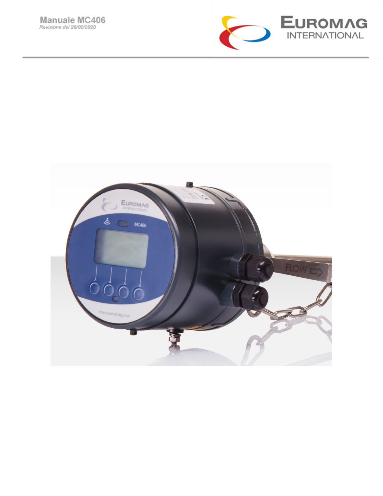
MC 406 CONVERTER
USE AND MAINTENANCE MANUAL

2
SUMMARY
1. INTRODUCTION…………………………………………………………………………………………...……3
1.1 MANUFACTURER’S NOTICE………………………………………………………………………………..4
1.2 PACKAGING CHECK……………………………………………………………………………………..… 4
1.3 PRELIMINARY NOTES…………………………………………………………………………………….…4
1.4 PRODUCT IDENTIFICATION………………………………………………………………………………..4
2 PRODUCT DESCRIPTION……………………………………………………………….…………………….5
2.1 GENERAL DESCRIPTION………………………………………………………………….………………..5
2.2 COUPLING……………………………………………………………………………………….…………….5
2.3 MEASUREMENT CHARACTERISTICS………………………………………………………….…………5
2.4 DATA STORAGE……………………………………………………………………………………….……..5
2.5 DISPLAY………………………………………………………………………………….……………………5
2.6 BATTERY……………………………………………………………………………….……………………..6
3 CONVERTER……………………………………………………………………………………………………7
3.1 SYSTEM START…………………………………………………………………………………..…….……7
3.2 USER INTERFACE……………………………………………………………………………..…….………8
3.3 DISPLAY OF THE TOTALIZER OVERFLOW COUNTER…………………………………...…………10
3.4 CELULAR COMMUNICATION………………………………………………………………….…………10
3.5 FIRST ACTIVATION……………………………………………………………………………….………..11
3.6 DISPLAY TEST………………………………………………………………………………….…………..11
3.7 FUNCTIONS…………………………………………………………………………………………………12
4. BATTERY LIFE………………………………………………………………………………………….……16
5. AUTO DIAGNOSTICS………………………………………………………………………………….……17
6. PC INTERFACE SOFTWARE………………………………………………………………………………18
6.1 FIRMWARE UPDATE………………………………………………………………………………………19
6.2 LOG OF DOWNLOAD ATTEMPT…………………………………………………………………………20
7. GSM……………………………………………………………………………………………………………21
7.1 MAIN FEATURES…………………………………………………………………………………………..22
7.2 GSM CONNECTION………………………………………………………………………………………..23
7.3 DEVICE SETTINGS………………………………………………………………………………………...24
7.4 PHONE NUMBER AND EMAIL SETTINGS……………………………………………………………..25
7.5 SCHEDULING…………………………………………………………………………………………….…26
7.6 DATA SAVING…………………………………………………………………………………………….…27
7.7 TEST………………………………………………………………………………………………………….28
8. 4-20mA OUTPUT MODULE…………………………………………………………………………………29
9. BLUETOOTH –MODBUS MODULE………………………………………………………………………30
9.1 BLUETOOTH COMMUNICATION………………………………………………………………………..31
9.2 PC CONNECTION THROUGH SOFTWARE INTERFACE…………………………………………...32
10. CONVERTER INSTALLATION………………………………………………………………………..….39
10.1 GROUNDING RECOMMENDATION……………………………………………………………...…...34
10.2 SEPARATE CONFIGURATION…………………………………………………………………………35
11. DISPOSAL OF THE CONVERTER………………………………………………………………………36
12. REPAIR REQUEST FORM (RMA)… ……………………………………………………………………37

3
1. INTRODUCTION
IMPORTANT WARNING
IT IS VERY IMPORTANT THAT ALL THE STAFF OPERATING THE EQUIPMENT HAVE READ THE
INCLUDED THE INSTRUCTIONS AND INDICATIONS PROVIDED IN THIS MANUAL AND THAT FOLLOWS
THEM BEFORE USING THE EQUIPMENT ITSELF
THE MANUFACTURER DOES NOT ASSUME ANY LIABILITY FOR THE CONSEQUENCES ARISING FROM
IMPROPER USE BY THE OPERATOR
The operator is responsible for the suitability of the device for the specific purpose.
Inadequate installation and use of the devices (systems) voids the warranty.
• The manufacturer will not be liable for any kind of damage resulting from the use of its products, including, but not limited
to those deemed direct, indirect, incidental, punitive and consequential. The installation, connection, commissioning and
maintenance must be performed by staff specifically qualified and authorized for that purpose.
• The installation personnel must ensure that the measuring system is correctly connected in accordance with the wiring
diagram.
For applications that require high working pressures or substances that may be hazardous to the people, the environment,
equipment or anything else if a pipe breakage occurs, Euromag International recommends, that before installing the
sensor the operator takes the appropriate precautions such as precautions such as the correct location, protection or the
mounting of a guard or safety valve. The device contains live electrical components, thus the installation, monitoring and
maintenance must be carried out by qualified and experienced staff fully aware of all the necessary precautions. Before
opening any inner part, please disconnect the power supply. The flow meter consists of metal and plastic parts, all of
which must be in compliance with local rules and requirements concerning waste disposal.
1.1 MANUFACTURER’S NOTICE
•While designing the device stresses and loads possibly caused by earthquakes, traffic, strong winds and fire
damage were not taken into account.
•Do not install the device so that it acts as a focus for pipeline stresses. In the configuration of the device please
take into account any external loads.
•During operation do not exceed the pressure and/or temperature ratings indicated on the nameplate or in this
Operating Manual.

4
1.2 PACKAGING CHECK
At the time of purchase and / or receipt of the product, the buyer is strongly invited to check the quality of the packaging
which must be intact, free of obvious signs of dents and completely and correctly closed.
When opening the packaging, also check that the product in regards of quality and verify all components / accessories as
reported in the package.
1.3 PRELIMINARY NOTES
The main parts that make up the electromagnetic flow meter are:
• The sensor - is installed in the pipes with the help of flanges or threaded connections.
• The converter - can be installed on the sensor (in the compact version) or in its vicinity (in the remote version) connected
by two cables.
Electromagnetic flow meters have many important advantages over their mechanical counterparts, which include among
others: exceptional long-term stability, maximum process reliability, zero maintenance. As a result, these sensors can
provide accurate and reliable measurements for many years.
See the following paragraphs for more detailed indications on correct use and installation.
1.4 PRODUCT IDENTIFICATION
An adhesive identification plate is attached to each MC406 Converter produced by Euromag International
on which the following are reported.
•Model: sensor and converter model
•CE conformity mark
•S/N: serial number that identifies the converter and the sensor
•Y: year of construction
•Size: nominal diameter, standard and nominal pressure flanges
•Q3: nominal flow rate and ratio R (Qnom / Qmin)
•Power Supply: supply voltage and / or battery
•MAP: instrument nominal pressure
•Press. loss class: max pressure drop class in the sensor
•Env. class: environmental class
•EMC class: Electromagnetic Compatibility class
•T: totalizer that cannot be reset
P: resettable partial totalizer
THE IDENTIFICATION PLATE MUST NOT BE REMOVED, DAMAGED OR IMPAIRED. IT MUST ALSO BE KEPT
CLEAN FROM DIRT AND MISCELLANEOUS ADHESIONS AS THE DATA CONTAINED IN IT REPRESENTS THE
ONLY SAFE AND UNIQUE WAY TO RECOGNIZE THE TYPE OF CONVERTER IN YOUR POSSESSION WHICH IS
INFORMATION NEEDED TO FILL IN THE REPAIR REQUEST FORM ATTACHED IN THIS MANUAL.

5
2 PRODUCT DESCRIPTION
2.1 GENERAL DESCRIPTION
MC406 is an electronic converter that, paired with an Euromag electromagnetic sensor, is able to offer
high precision and stability in compact dimensions. The measured flow rate is displayed on the LCD screen together with
one of the 4 totalizers available; other information and some basic settings are directly accessible using the 4-button
interface.
The two independent positive and negative pulse outputs allow connection with any external meter (max 30 V ac or dc /
100 mA). The required power supply is between 12 and 24 V DC and a battery pack can be connected to attain
uninterrupted service even in the event of a power failure. A GSM module can also be installed to allow remote
transmission of measurements *
2.2 COUPLING
The maximum diameter of the sensor that can be used with this converter is 600 mm; backup battery life is affected by the
size of the sensor.
The flow meter can be ordered both in a compact and separate version, with a maximum length of 30mt cable.
2.3 MEASUREMENT CHARACTERISTICS
Flow speed range: from 0.015 m/s to 10 m/s
Liquid conductivity> = 20uS / cm
Sampling: 3.125Hz nominal powered unit (depends on the diameter); battery mode (low power): from 1/5Hz at 1/60Hz
(default 1/15Hz)
2.4 DATA STORAGE
All parameters, totalizers and the register are stored in a non-volatile memory.
2.5 DISPLAY
The LCD can display an 8 and a 6-digit number plus different information icons, allowing the user to view different
information and set many parameters. The details of what can be shown:
•Instant flow
•Positive totalizer (T+)
•Negative totalizer (T-)
•Partial Positive (P+)
•Partial negative (N-)
•Date and time
•Converter temperature
•Code and value of the corresponding parameter
* the data transmitted remotely are not considered legally relevant and have the sole purpose of providing one
remote viewing. The integrity and correctness of the data transmitted are not covered by the MID certification.
Table of contents
Other Euromag Media Converter manuals


Popular Media Converter manuals by other brands


H&B
H&B TX-100 Installation and instruction manual

Bolin Technology
Bolin Technology D Series user manual

IFM Electronic
IFM Electronic Efector 400 RN30 Series Device manual

GRASS VALLEY
GRASS VALLEY KUDOSPRO ULC2000 user manual

Linear Technology
Linear Technology DC1523A Demo Manual

Lika
Lika ROTAPULS I28 Series quick start guide

Weidmuller
Weidmuller IE-MC-VL Series Hardware installation guide

Optical Systems Design
Optical Systems Design OSD2139 Series Operator's manual

Tema Telecomunicazioni
Tema Telecomunicazioni AD615/S product manual

KTI Networks
KTI Networks KGC-352 Series installation guide

Gira
Gira 0588 Series operating instructions

Lika
Lika SFA-5000-FD user guide