Euromag MC608 Series User manual

MC608 Converter
Installation Manual
Vers. 6.0 and subsequent
PLEASE READ THESE INSTRUCTIONS
AND KEEP IN A SAFE PLACE
TD 210-1-ENG


IT IS VERY IMPORTANT THAT ALL THE STAFF WORKING WITH THE EQUIPMENT HAVE
READ AND FULLY UNDERSTOOD THE INSTRUCTIONS AND
INFORMATION PROVIDED IN THIS MANUAL AND FOLLOW AND APPLY THEM BEFORE
USING IT. THE MANUFACTURER IS NOT
LIABLE FOR ANY CONSEQUENCES RESULTING FROM MISUSE BY THE OPERATOR.
PLEASE READ AND KEEP THESE INSTRUCTIONS IN A SAFE PLACE
This manual can be downloaded from the internet www.euromag.com visiting the download area.
To ensure a proper and safe installation we strongly recommend thoroughly reading this operation manual.
IMPORTANT WARNING
The operator shall bear responsibility for the suitability of the device for the specific purpose:
Improper installation and operation of the devices (systems) will cause warranty to be void
• The manufacturer will not be liable for any kind of damage resulting from the use of its products,
including, but not limited to those deemed direct, indirect, incidental, punitive and consequential. The
installation, connection, commissioning and maintenance must be performed by staff specifically
qualified and authorized for that purpose.
• The installation personnel must ensure that the measuring system is correctly connected in accordance
with the wiring diagram.
For applications that require high working pressures or substances that may be hazardous to the
people, the environment, equipment or anything else if a pipe breakage occurs, Euromag International
recommends, that before installing the sensor the operator takes the appropriate precautions such as
precautions such as the correct location, protection or the mounting of a guard or safety valve.
The device contains live electrical components, thus the installation, monitoring and maintenance must
be carried out by qualified and experienced staff fully aware of all the necessary precautions. Before opening
any inner part, please disconnect the power supply.
The flow meter consists of metal and plastic parts, all of which must be in compliance with local rules and
requirements concerning waste disposal.
CE/EMC/Norme
CRUCIAL INFORMATION AND INSTRUCTIONS TO BE APPLIED.
PLEASE REFER TO THE ANNEXED DOCUMENTS .
CAUTION!
RISK OF ELECTRIC SHOCK!
ALL OPERATIONS MARKED WITH THIS SYMBOL SHOULD ONLY BE CARRIED OUT BY
QUALIFIED TECHNICIANS.
CAUTION!
INFORMATION AND INSTRUCTION
REQUIRING SPECIAL ATTENTION.
NOTE
The manual that describes this flowmeter conforms to the following safety rules:
• Directives EN 61326-1:2006, EN 55011:2009 + / A12010, EN 6100-3 (2/3), EN 6100-4 (2/3/4/5/6/8/11).
• Directive EN61010-1 (pending)
• Directive EN 60529 (pending)
• It is in class A.
In addition, it is essential to read the manual start-up that accompanies the flow meter and which is
contained in the package.

Manufacturer’s design and safety statement
• Responsibility for the choice of lining and electrode materials in regards to abrasion and corrosion
resistance lies with the purchaser. The effect of any change in fluid process during the operation of the
device must be taken into account. Incorrect selection of lining and/or electrode could lead to a failure
of the device.
• While designing the device stresses and loads possibly caused by earthquakes, traffic, strong winds and
fire damage were not taken into account.
• Do not install the device so that it acts as a focus for pipeline stresses. In the configuration of the device
please take into account any external loads.
• During operation do not exceed the pressure and/or temperature ratings indicated on the nameplate or
in this Operating Manual.
Battery Operation:
• Lithium batteries are primary power sources with high energy content. They are designed to meet the
highest possible safety standards. They may, however, pose a potential hazard if they are misused either
electrically or mechanically which may cause the generation of excessive heat and possible breakage
of the cell.
Thus the following basic precautions should be observed when handling and using lithium batteries:
- Do not short-circuit, recharge, overcharge or connect with incorrect polarity
- Do not expose to temperature beyond the specified temperature range or incinerate the battery
- Do not crush, puncture or open cells or disassemble battery packs
- Do not weld or solder to the body of the battery, or the battery packs
- Do not expose contents to water
Lithium batteries are regulated under United Nations Model Regulations on Transport of Dangerous goods
(UN document on transport of hazardous goods), UN ST/SGAC document. 10-1, 12th revised edition, 2001.
The UN document No. 3091
Class 9 covers the lithium batteries packed with the equipment or inserted into it. The UN document No.
3090 Class 9 only covers the transport of the batteries themselves.
Thus the following basic precautions should be followed when transporting lithium batteries:
- Transport only in special packaging with special labels and transportation documents.
- Use caution in handling, transporting and packaging in order to prevent short circuiting of the batteries.
- The gross mass of the package is limited according to the type of transportation. In general, a gross
mass of less than 5 kg is acceptable for all forms of transport
- The batteries comply with the requirements set out in “UN Manual of tests and criteria, Part III,
subsection 38.3” for transport by air and with the provisions of the ADR regulations for the transport by
truck/sea.
• Remove the battery from the transmitter before returning the flow meter to Euromag International for
possible service or warranty claim.

6
EUROMAG | MC608 | TD210-1
www.euromag.com
SUMMARY
MANUFACTURER’S DESIGN AND SAFETY STATEMENT 5
BATTERY OPERATION 5
1. PRELIMINARY NOTES 10
2. GENERAL PRECAUTIONS 10
3. SENSOR INSTALLATION 12
3.1 IDENTIFICATION NAMEPLATE 12
3.2 BIDIRECTIONAL READING 12
3.3 INSTALLATION INSTRUCTIONS 13
3.3.1 POSITIONING IN RELATION TO THE PLANT 13
3.3.2 POSITIONING IN RELATION TO THE FLOW 14
3.3.3 IMPORTANT INSTRUCTIONS ON MOUNTING 15
3.3.4 CHARTS OF MAXIMUM ALLOWABLE TORQUES 15
3.3.5 IMPORTANT GUIDELINES FOR CORRECT INSTALLATION 17
3.3.6 IMPORTANT GENERAL INFORMATION FOR A PROPER INSTALLATION 20
3.3.7 INSTALLATION EXAMPLE OF WAFER METER (MUT1000EL – MUT1100J) 21
4. POTENTIAL EQUALIZATION 22
5. NEGATIVE PRESSURE IN THE PIPE 24
6. INSTRUCTIONS FOR DIAMETER REDUCTION 24
7. INFORMATION CONCERNING THE MC608R CONVERTER 25
8. INSERTION METERS 26
8.1 INTRODUCTION 26
8.1.1 FEATURES AND BENEFITS 26

7
8.1.2 SYSTEM DIAGRAM 27
8.1.3 MECHANICAL INSTALLATION 27
8.2 INSTALLATION 28
8.2.1 MEAN AXIAL VELOCITY POINT (1/8 OF THE INTERNAL DIAMETER) 29
8.2.2 ALIGNMENT 29
8.2.3 PROGRAMMING 29
9. MC 608 CONVERTER 30
9.1 INSTALLATION 30
9.1.1 IDENTIFICATION NAMEPLATE 30
9.1.2 COMPACT VERSION 30
9.1.3 REMOTE VERSION 31
9.1.4 ELECTRICAL CONNECTIONS 34
9.1.5 MODBUS RS485 OUTPUT 37
9.1.6 ELECTRICAL GROUNDING OF THE COVERTER CASE 37
9.1.7 CONNECTION TO THE POWER SUPPLY 38
9.2 MC608 CONVERTER PROGRAMMING 38
9.2.1 PROGRAMMING 41
10. DESCRIPTION OF THE MENU 44
10.1 OPTIONS 44
10.1.1 TECHNICAL UNITS 44
10.1.2 MEASUREMENT FREQUENCY 45
10.1.3 DISPLAY 45
10.1.4 VIEW OPTIONS 46
10.1.5 FULL SCALE FLOW RATE 46

8
EUROMAG | MC608 | TD210-1
www.euromag.com
10.1.6 LANGUAGE 46
10.2 COUNTERS 46
10.3 PARAMETERS 47
10.3.1 KA SETUP 47
10.3.2 DIAMETER SETUP 47
10.3.3 FILTERS SETUP 48
10.3.4 ZERO FINDER 50
10.3.5 FLOW RATE ALARMS 50
10.3.6 EMPTY PIPE THRESHOLD 50
10.4 I/O 51
10.4.1 PULSE OUTPUT 51
10.4.2 FREQUENCY OUTPUT 52
10.4.3 PROGRAMMABLE OUTPUT 52
10.4.4 PROGRAMMABLE INPUT 53
10.4.5 BATCHING 53
10.4.6 PROGRAMMABLE OUT LOGIC 54
10.5 OTHERS 54
10.5.1 SYSTEM INFO 54
10.5.2 TIME/DATE 54
10.5.3 RESERVED 54
10.5.4 GRAPH 54
10.5.5 SIMULATION 54
10.5.6 COMMUNICATIONS 54
10.5.7 DATA CONNECTION (RS485/IRCOMM) 54

9
10.6 MEMORY 55
10.6.1 LOAD USER COPY 55
10.6.2 SAVE USER COPY 55
10.6.3 FACTORY SETTINGS 55
10.6.4 DATALOGGER 55
10.6.5 PASSWORD SETUP 57
11. TECHNICAL DATA 58
11.1 GENERAL FEATURES 58
11.2 CERTIFICATES AND APPROVALS 59
11.4 ACCURACY 60
12. RETURN OF THE FLOW METER FOR ANY CHEK OR REPAIR 61
13. APPENDIX - TROUBLESHOOTING 62
REPAIR APPLICATION FORM 65
NOTE 66

fig_2_1 fig_2_2
10
EUROMAG | MC608 | TD210-1
www.euromag.com
1. PRELIMINARY NOTES
The main parts composing the electromagnetic flow meter consists of:
A. The sensor – is installed in the pipes using flanges or threaded attachments or clamp attachments
B. The converter – may be installed on the sensor (in compact version), or nearby (in remote version)
connected via two cables.
Electromagnetic flow meters have many important advantages with respect to relevant mechanical
counterparts, including among the others: outstanding long term stability, maximum process reliability, no
need for maintenance. Consequently, these sensors can deliver accurate and reliable measurements for
many years.
Please see the paragraphs below for more detailed instructions on correct installation.
ELECTROMAGNETIC FLOW METERS ARE SPECIFICALLY DESIGNED
TO WORK UNDER FEW BASIC CONDITIONS:
1. LIQUID MUST BE CONDUCTIVE
2. THE PIPE MUST ALWAYS BE COMPLETELY FILLED
3. INLET AND OUTLET DISTANCES MUST BE THOSE RECOMMENDED
NOTE
2. GENERAL PRECAUTIONS
The proper lifting method is shown in Figure fig_2_1, while it must be avoided that shown in Figure fig_2_2; to
be noticed, do NOT raise the flow meter gripping the converter, but always holding it on the sides.
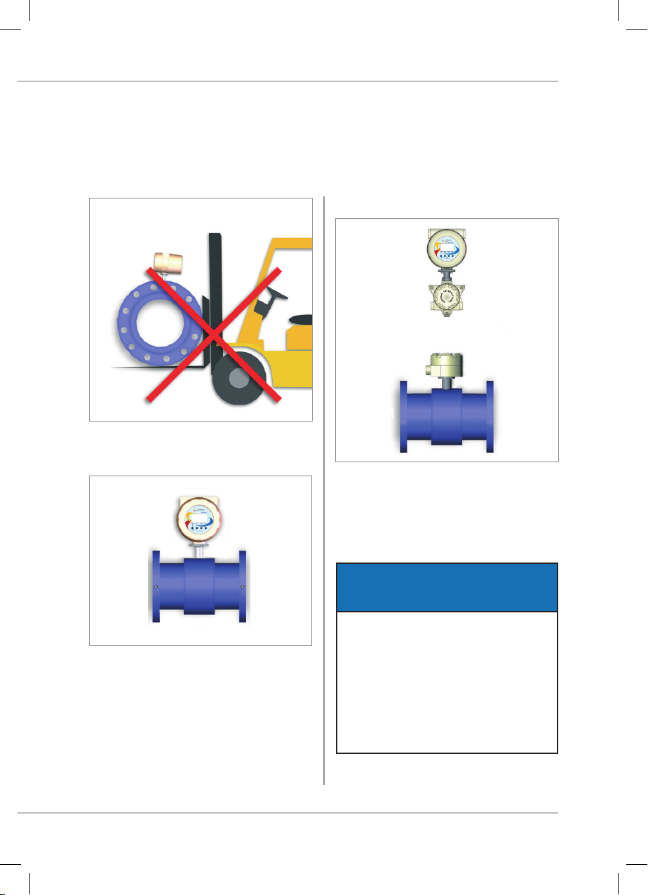
fig_2_3
fig_2_4
fig_2_5
11
Moreover:
DO NOT move the flow meter with the lifting device without the original packaging or without the help
of an appropriate support, ensuring the required stability.
2. GENERAL PRECAUTIONS
THE JUNCTION BOX ON THE
SENSOR IS DESIGNED TO BE IP68
PROTECTED ONLY WHEN PROPERLY
CLOSED AND FULL TIGHTENED.
THE MANUFACTURER ACCEPTS NO
LIABILITY FOR IMPROPER CLOSING
CARRIED OUT BY THIRD PARTIES.
NOTE
Compact version
Separate version
IP67 (Nema 4X)
• possibility of immersion 1 meter;
• maximum immersion time 12 hours. Separate
version
IP67 Electronics (Nema 4x)
IP68 Sensor (Nema 4x)
• possibility of continuous immersion in 1.5
metres water column.

fig_3_1
12
EUROMAG | MC608 | TD210-1
www.euromag.com
3. INSTALLATION OF
THE SENSOR
3.1 IDENTIFYING DATA PLATE
The plate located on the sensor carries the
following data:
• MODEL:
• PART No.: the part number identifying the
device (identification number for tracing the
identity)
• DN: nominal diameter [inches or mm]
• PN nominal pressure [bar/s]
• Temp.: maximum process temperature
• IP: international degree of protection
• ELECTRODES: composition of the material
making up the electrodes
• LINING: internal lining material
• KA: calibration coefficients
• ART.: other special guidelines
3.2 BIDIRECTIONAL READING
In the sensor, if the liquid flows:
• in the same direction of the arrow (enter by – and exit by +), the flow is positive and the display will
show a reading with no sign;
• in the opposite direction to that indicated by the arrow (enter by + and exit by –), the flow is negative
and the display will show a reading with negative sign;
FLOW direct flow -> figure without signnegative figure-> reverse flow
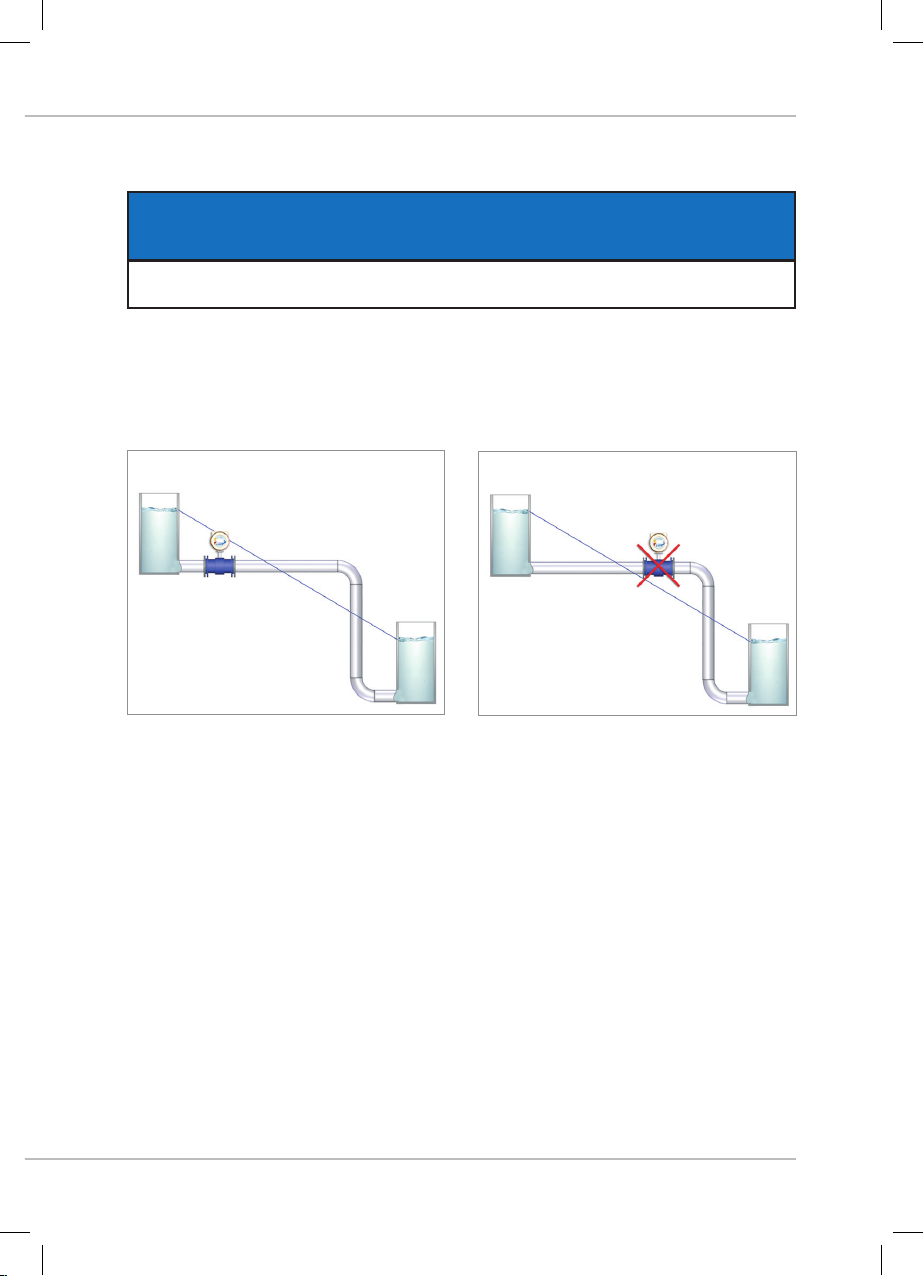
fig_331_2
fig_331_1
13
3.3.1 POSITIONING IN RELATION TO THE PLANT
For efficient working conditions, please carefully follow the instructions in figure 3_3_1.
The flow meter must remain below the hypothetical blue line (piezometric level line) which connects the
two levels of fluid to be measured.
3. INSTALLATION OF THE SENSOR
THE SENSOR MUST ALWAYS BE COMPLETELY FULL WITH LIQUID!
IMPORTANT NOTE
INSTALLATION INSTRUCTIONS
Avoid placing the flow meter above the piezometric
level line
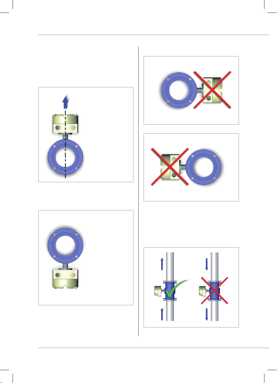
fig_332_5
fig_332_4
fig_332_3
fig_332_1
fig_332_2
14
EUROMAG | MC608 | TD210-1
www.euromag.com
3.3.2 POSITIONING IN RELATION TO THE
FLOW
With installations on horizontal pipes, the converter
(or the junction box in the separate version) must
be placed upright to ensure the proper functioning
of the empty pipe detection.
In case of obstruction, follow the guidelines as
explained in the figures below.
Avoid following positions:
Recommended installation is on a vertical/inclined
pipe with upward flow direction, to minimize the
wear and deposits in the sensor. Avoid installation
in vertical pipes with free outlet.
The only position
that can assure
correct empty pipe
detection
Installation
NOT enabling
the empty pipe
detection
TOP
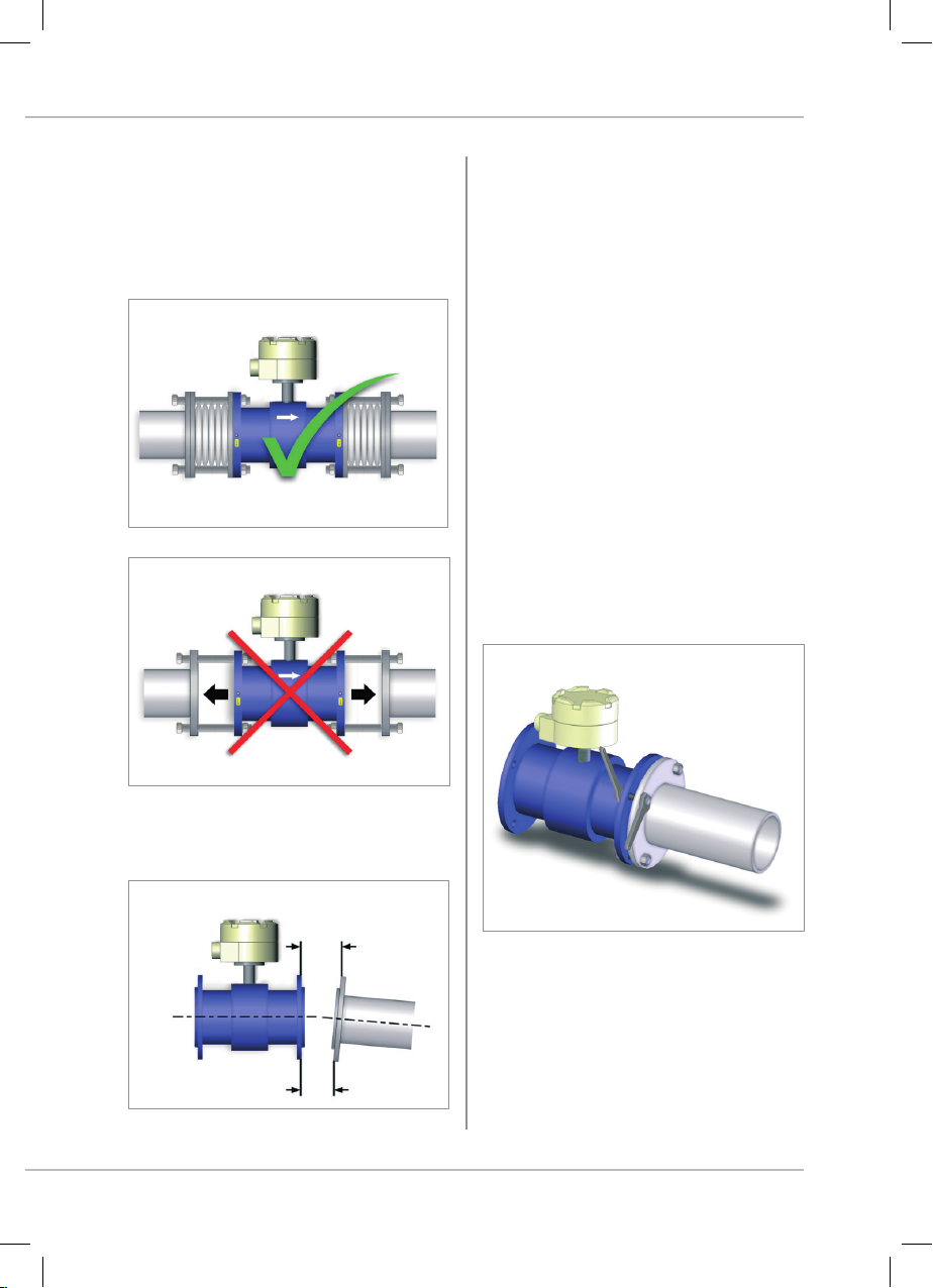
fig_333_3
fig_334_1
fig_333_2
fig_333_1
15
3.3.4 CHARTS OF MAXIMUM
ALLOWABLE TIGHTENING TORQUES
Standard bolts must be well lubricated and tightened
evenly around the gasket. If the bolts are tightened
excessively, they may result in leaks or damage to
the flow meter or to the pipe. Carefully follow any
instructions provided by the graphics, carefully check
the correct centring of the sensor before attaching the
flanges and then proceed by following the steps below:
Step 1. approx 50% of maximum tightening torque;
Step 2. approx 80% of maximum tightening torque;
Step 3 100% of the maximum tightening torque
provided in the chart.
All values are theoretical and were calculated
for optimum conditions and use with carbon steel
flanges.
3.3.3 IMPORTANT INSTRUCTIONS ON
MOUNTING
Use elastic pipe fittings where there is not adequate
distance between the sensor and the pipe. Do not
attempt to bring the pipe to the sensor by tightening
the bolts.
Max. allowable deviation of pipe flange faces is
0.5mm
L max
L max. - L min. ≤5 mm
3. INSTALLATION OF THE SENSOR

16
EUROMAG | MC608 | TD210-1
www.euromag.com
PPBT+ MUT 1100J FIBREGLASS
Sensor Maximum operating pressure Pipe flange - Flange - Class Max. allowable tightening
torques
[bar] [psig] flange class [Nm] [ftlb]
DN 40 ≤10 ≤145 DN 40 PN 16/40 25 13
DN 50 ≤10 ≤145 DN 50 PN 16/40 35 19
DN 65 ≤10 ≤145 DN 65 PN 16/40 35 19
DN 80 ≤10 ≤145 DN 80 PN 16/40 35 19
DN 100 ≤10 ≤145 DN 100 PN 16/40 45 24
DN 125 ≤10 ≤145 DN 125 PN 16/40 65 35
DN 150 ≤10 ≤145 DN 150 PN 16/40 85 45
DN 200 ≤10 ≤145 DN 200 PN 16/40 100 53
1 1/2” ≤10 ≤145 1 1/2” 150/300 25 13
2” ≤10 ≤145 2” 150/300 35 19
2 1/2” ≤10 ≤145 2 1/2” 150/300 35 19
3” ≤10 ≤145 3” 150/300 35 19
4” ≤10 ≤145 4” 150/300 45 24
5” ≤10 ≤145 5” 150/300 65 35
6” ≤10 ≤145 6” 150/300 85 45
8” ≤10 ≤145 8” 150/300 100 53
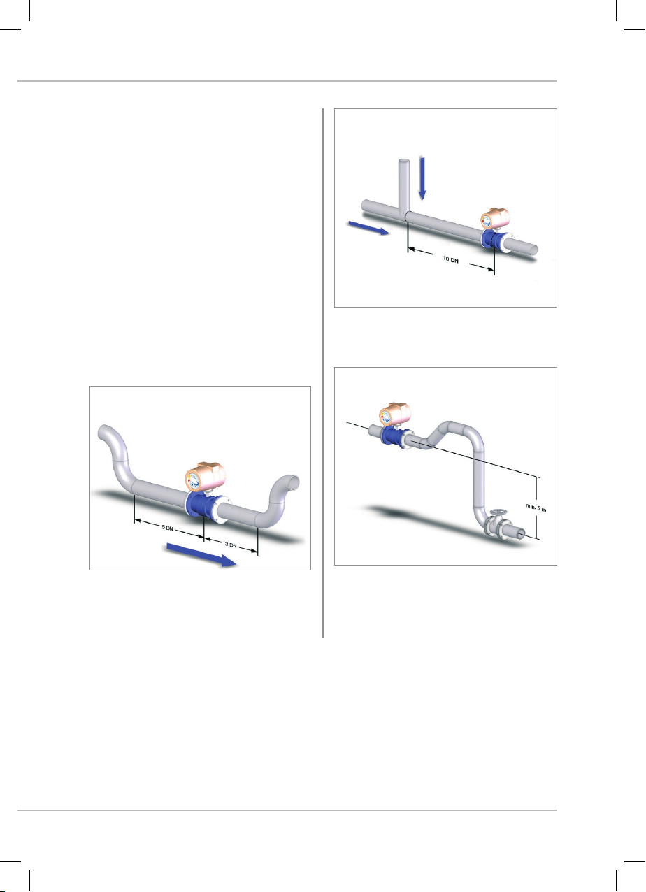
fig_335_1 fig_335_3
fig_335_2
17
3.3.5 IMPORTANT GUIDELINES FOR
CORRECT INSTALLATION
For a correct working condition please follow
the important guidelines shown in the following
figures. Improper installation result in inaccurate
measurement.
To achieve the most accurate flow measurement
it is essential to have minimum straight lengths
of the inlet and outlet pipes as shown (DN: sensor
nominal diameter)
• For partially filled pipes or pipes with downward
flow and free outlet, the flow meter should be
located in a U-tube, respecting the upward and
downward lengths between the curves.
• In the case of T-connection between two
different tubes, please keep a 10DN distance
upstream of the flow meter.
• Keep 5 meters between the axis of the flow
meter and those of the gate valve placed
downstream.
3. INSTALLATION OF THE SENSOR

fig_335_5
fig_335_7
fig_335_6
fig_335_4
18
EUROMAG | MC608 | TD210-1
www.euromag.com
RECOMMENDED INSTALLATIONS ( ) AND THOSE TO BE AVOIDED ( ):
• In this installation the sensor is full with liquid • The position on the left is correct, the other two
ARE NOT.
• DO NOT place the sensor close to any variation
in the path of the flow.
• This installation DOES NOT guarantee a full pipe
condition.
THE SENSOR MUST ALWAYS BE COMPLETELY FULL WITH LIQUID!
IMPORTANT NOTE

fig_335_12
fig_335_9
fig_335_10
fig_335_11
fig_335_8
19
• DO NOT install the sensor in vertical pipes with
free outlet or at the highest point in the pipe
system
• Always install the sensor downstream the pump
and NEVER upstream to avoid vacuum.
• DO NOT use the sensor as a support for the tube.
• The tube must act as a support for the flow
meter.
• DO NOT place any gate valve directly connected
upstream the sensor.
3. INSTALLATION OF THE SENSOR
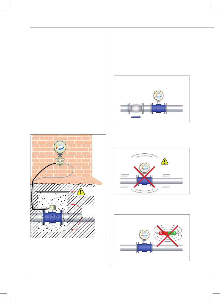
fig_335_15
fig_336_2
fig_336_3
fig_336_1
20
EUROMAG | MC608 | TD210-1
www.euromag.com
UNDERGROUND INSTALLATIONS
• The remote sensor is protected to IP68/NEMA
6P and can be positioned underground. We
recommend the use of gravel for at least
300mm (12 inches) around the sensor. This
provides certain drainage and prevents dirt from
solidifying on the sensor, in addition it facilitates
its location whenever new excavations are
required. Before covering the gravel with earth,
we suggest using electrical cable identification
tape above the gravel itself.The remote sensor
cable should pass through a conduit made of
plastic and of minimum 50mm (2 inches).
• It is recommended the junction box made of
steel in the case of underground installations.
3.3.6 IMPORTANT GENERIC INDICATIONS
FOR A CORRECT INSTALLATION
• Install a suitable anti-vibrational protection if
any vibration arise.
• DO NOT expose the flow meter to vibrations and/
or movement, which may affect its performance
and duration.
• AVOID exposing the flow meter to strong or
nearby magnetic fields.
Protective cover
Fill with an
adequate amount
of material
AVOID ANY
EXCESSIVE
VIBRATIONS
Other manuals for MC608 Series
1
This manual suits for next models
3
Table of contents
Other Euromag Media Converter manuals


