Axioscope 5/7/Vario Contents / List of Illustrations ZEISS
03/2018 430035-7344-001 7
Fig. 3-20 Plugging in the power cable of the motorized mechanical stage ........................................ 56
Fig. 3-21 Mounting the condenser carrier ........................................................................................ 57
Fig. 3-22 Mounting the condenser .................................................................................................. 57
Fig. 3-23 Mounting the darkfield condenser .................................................................................... 58
Fig. 3-24 Mounting the stage carrier ............................................................................................... 59
Fig. 3-25 Removing the HAL 50 halogen illuminator from the stand ................................................. 60
Fig. 3-26 Inserting halogen lamp 12 V, 50 W................................................................................... 60
Fig. 3-27 Mounting the TL LED10 illuminator or RL LED10 illuminator............................................... 61
Fig. 3-28 Mounting the base plate................................................................................................... 62
Fig. 3-29 Mounting the HAL 100..................................................................................................... 63
Fig. 3-30 Adjusting the HAL 100 ..................................................................................................... 64
Fig. 3-31 Changing the HAL 100..................................................................................................... 65
Fig. 3-32 Inserting the adjustment tool ............................................................................................ 66
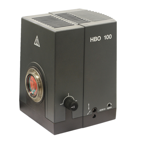
Fig. 3-33 Mounting the HBO 100 .................................................................................................... 67
Fig. 3-34 Power supply unit for HBO 100......................................................................................... 67
Fig. 3-35 Adjustment tool ............................................................................................................... 68
Fig. 3-36 Adjusting the HBO 100..................................................................................................... 68
Fig. 3-37 Mounting the illumination system Colibri 3 ....................................................................... 69
Fig. 3-38 Changing the LED modules in the Colibri 3 illumination system.......................................... 70
Fig. 3-39 Mounting the binocular tube with intermediate plate ........................................................ 72
Fig. 3-40 Mounting the magnification changer ................................................................................ 73
Fig. 3-41 Changing the filters in the reflector module FL P&C........................................................... 74
Fig. 3-42 Mounting the filters and the color splitter.......................................................................... 74
Fig. 3-43 Opening the module ........................................................................................................ 75
Fig. 3-44 Changing the color filter................................................................................................... 75
Fig. 3-45 Labeling the color splitter.................................................................................................. 76
Fig. 3-46 Mounting the polarizer D.................................................................................................. 76
Fig. 3-47 Mounting the low-power system ...................................................................................... 77
Fig. 3-48 Inserting the modulator disk in the 0.9/1.25 H condenser .................................................. 78
Fig. 3-49 Mounting the slit-diaphragm ............................................................................................ 79
Fig. 3-50 Changing the PhC-DIC-PlasDIC diaphragm........................................................................ 79
Fig. 3-51 Changing the filter in the filter wheel transmitted light...................................................... 80
Fig. 3-52 Lower stand part for HAL 50 illumination (proceed similarly for LED illumination)................ 81
Fig. 3-53 Lower stand part for HAL 100 illumination ........................................................................ 82
Fig. 3-54 External power supply unit for two lamps (front and back)................................................. 82
Fig. 3-55 Power supply unit for HBO 100 (front and back)................................................................ 83
Fig. 4-1 Setting the inter-pupillary distance on the binocular tube................................................... 85
Fig. 4-2 Setting the viewing height on the binocular tube............................................................... 85
Fig. 4-3 Microscope adjustment in transmitted light brightfield microscopy..................................... 88
Fig. 4-4 Adjusting the height stop on the condenser carrier............................................................ 89
Fig. 4-5 Adjusting the height stop on the focusing drive................................................................. 89
Fig. 4-6 Centering the darkfield diaphragm on the condenser, achromatic-aplanatic 0.9 H D PhC
DIC .................................................................................................................................. 90
Fig. 4-7 Centering the annular phase diaphragm (light-colored, in the condenser) and the phase
ring (dark-colored, in the object) ....................................................................................... 94
