EUROPRO 0701AREN30MAS User manual

EUROPE PROJECTION - 228, avenue Olivier Perroy 13790 ROUSSET - Tél : +33 (0)4 42 29 08 96 – Fax : +33 (0)4 42 53 44 36
SAS au capital de 400 000 € - RCS Aix-en-Provence B 394 961 510 - NAF 2892 Z - Intracom : FR 54 394 961 510
User manual
Edition of 07/04/2020
Mini-Sandblaster 30L

INSTRUCTIONS AND MAINTENANCE MANUAL
2
INDEX
THANKS.................................................................................................................................................... 2
1. MANUAL AIMED TO............................................................................................................................. 3
2. INFORMATION REMARK..................................................................................................................... 3
3. GUARANTEE........................................................................................................................................ 4
4. WASTE PRODUCTS AND ENVIRONMENT........................................................................................ 4
5. EQUIPMENT DESCRIPTIONS ............................................................................................................. 4
5.1. GENERAL DESCRIPTION.............................................................................................................................4
5.2. MAIN COMPONENTS....................................................................................................................................5
5.3. IDENTIFICATION PLATE...............................................................................................................................6
5.4. TECHNICAL FEATURES ...............................................................................................................................7
5.5. REGULATION ................................................................................................................................................7
5.6. SAFETY SYSTEMS........................................................................................................................................8
6. EQUIPMENT INSPECTION WHEN RECEIVED................................................................................... 8
7. USE INSTRUCTIONS ........................................................................................................................... 9
7.1. PRIOR OPERATIONS....................................................................................................................................9
7.2. TANK LOADING.............................................................................................................................................9
7.3. WORKING PRESSURE REGULATION .........................................................................................................9
7.4. ABRASIVE PRODUCT OUTLET REGULATION..........................................................................................10
7.5. CONTROL OF THE ABRASIVE OUTLET ON LEAVING SANDING............................................................10
8. COMPONENTS DISMANTLE............................................................................................................. 11
8.1. TIPS DISMANTLE ........................................................................................................................................11
8.2. PRODUCT HOSE DISMANTLE ...................................................................................................................11
8.3. TANK TOP DISMANTLE ..............................................................................................................................11
9. PIECES OF ADVICE TO AVOID INAPPROPIATE AND DANGEROUS PRACTICES..................... 12
10. COMPLETE SPARE PARTS DISMANTLE...................................................................................... 14
TROUBLESHOOTING ............................................................................................................................ 17
12. EQUIPMENT STORAGE................................................................................................................... 18
13. EQUIPMENT WITHDRAW................................................................................................................ 18
14. INSPECTIONS AND PERIODICAL TESTS...................................................................................... 18
CONFORMITY DECLARATION ............................................................................................................. 19
THANKS
EUROPE PROJECTION wants to thank the confidence shown in the acquired
precision sandblaster.
This trust motivates us to keep working daily for the consecutions of the highest quality
criteria of our products, to such an extent that they have became a reference on reliability and
exigencies fulfilling in the market aimed to.
Hoping the acquired product is of your complete satisfaction and being at your entire
disposition to assist any consultation or suggestion, please receive again our most sincere
thanks.

SANDBLASTER 0701AREN10MAS
3
1. MANUAL AIMED TO
EUROPE PROJECTION has elaborated the here shown Instructions manual and
maintenance as a document recommended to be attached to the precision sandblaster
for its whole useful life, considering it as other component of this one.
The Manual is aimed to the end user and technical assistant of the equipment and it
contains every useful information on safety related to:
Assembly
Fine tuning
Use
Manteinance, including testing by the end user
Dangers caused by an inappropiate use
2. INFORMATION REMARK
This document must be at disposal of the staff using and maintaining the equipment.
In order to assure that equipment features are the same as the ones specified in your
order, please, revise it when received and contact the authorized TAS (Technical Assistance
Service) in case you find any disagreement.
For these reasons, it is recommended that every repairing or substitution of
components into the equipment is done directly by specialized staff (Consult the manufacturer
for local Technical Service)
ATTENTION:
Any modification in the original configuration of the equipment or its components, as
well as its use to a different aim for which it has been designed, will imply the
immediate invalidation of the product homologation. This will free EUROPE PRO-
JECTION from any responsibility as manufacturer enterprise of the commercialized
equipment.
Moreover, the homologation invalidation will be caused by:
Welding operations on the pressure device.
Mechanization operations (drills, cuts, etc.)
Different assemblies to the original one
Substitution of elements different to the original ones
Safety valve manipulation
The following actions will cause a breakdown which is be covered by the guarantee:
To work with wet abrasives or with measures higher to recommended.
To put the machine in horizontal position with the tank full of abrasive
To fill the tank with abrasive till the very top.
To use the equipment near of the air compressor

INSTRUCTIONS AND MAINTENANCE MANUAL
4
3. GUARANTEE
The acquired equipment counts on a two years guarantee from the Invoice date. The
guarantee covers manufacturing defects and faults in components.
Elements repairs and substitution are only guaranteed if made by technical staff of
EUROPE PROJECTION or Official Technical Service.
Defectives pieces will be sent carriage paid.
The guarantee does not cover direct or indirect damages caused by our machine on
people or things, neither repairing operations made directly by the client or third people.
Guarantee does not cover:
Breakdowns or damages caused by an inappropiate use of the equipment.
Breakdowns or damages caused by spare parts different to the original ones
or recommended by EUROPE PROJECTION.
Breakdowns or damages caused by a wrong conservation.
Components subject to wear (tips, filters, hoses, etc.).
Guarantee is null:
When repairs and components substitutions are done in the equipment, without prior
authorization from EUROPE PROJECTION.
When the serial number identifying unequivocally every equipment is manipulated or
removed.
When breakdown is proved to be caused by an inadequate use of the equipment, by
a fall or a hit, or by causes not due to normal working conditions.
When the equipment is dismantled, manipulated or repaired without the authorization
of EUROPE PROJECTION.
Repair operations made on guaranteed equipments will not mean stop or extension of
guarantee period.
4. WASTE PRODUCTS AND ENVIRONMENT
5. EQUIPMENT DESCRIPTIONS
5.1. GENERAL DESCRIPTION
The bought equipment is a precision sandblaster aimed to small and medium precision
workings on decoration, metal or wood industry; based in the application of abrasive products
on the surface to be treated.
Amongst the possible applications we can find:
Wall cleaning
Wood stripping
REMEMBER:
To get rid of pollutant and dangerous products, of packages, of equipments and
tools into disuse and in general of any type of waste produced by its activity, please
go to the Selective Collection and Treatment points suitable for each case.
If you need any information related to this, please go to the Environmental ministry
in your regional government or to the nearest city hall

SANDBLASTER 0701AREN10MAS
5
Paper and adhesive removing
Swimming pool stripping
Graffiti removing
Concrete cleaning and fitting
Plastic cleaning
Paving and flooring mark removing
Metallic surfaces preparation
Tank and metallic container clearing and stripping
This sansblaster allows us the application of the following types of abrasives: corindon,
metallic grain, glass, aluminium silicate, garnet, calcium carbonate and silica sand (grit).
Next, it is attached a table which will help the end user to choose the abrasive size
according to tip diameter.
Tip (mm)
Abrasive Granule Diam. (mm)
Minimum
Maximum
2,0
0,25
0,40
2,5
0,25
0,50
3,0
0,25
0,60
4,0
0,25
1,00
Table 1
The reference of the precision sandblaster model acquired is 0701AREN10.
5.2. MAIN COMPONENTS
Main components in the equipment are here shown graphically and listed.
Posit.
Denomination
1
Tank with wheels
2
Top
3
Product inlet
4
Regulation box and system
5
Working pressure regulador
6
Abrasive product outlet
7
Product outlet flow rate regulator
8
Product hose
9
Remote control circuit (pneumatic)
10
Safety valve
11
Air inlet to equipment
12
Gun
13
Carriage handle
14
Handle clamp
15
Handle clamp housing
16
Air inlet to tank
17
Cap
18
Purifier filter

INSTRUCTIONS AND MAINTENANCE MANUAL
6
19
Manometer
20
Air tank release
Table 2
5.3. IDENTIFICATION PLATE
Spare parts 1 –Main components

SANDBLASTER 0701AREN10MAS
7
The equipment is fitted with a identification plate that, under any case, can´t be
removed or manipulated.
The identification plate provides the following information:
Manufacturer name
Serial number and manufacturing date.
Main characteristics.
Other compulsory data, according to application regulation.
To make any enquiry to EUROPE PROJECTION, related to the equipment, it will
be neccessary to refer to the serial number on the identification plate.
5.4. TECHNICAL FEATURES
The precision sandblaster technical features are shown in the
table as follows:
0701AREN30MAS
Weight
31,5 kg
Tank capacity
30 l.
Min. working pressure
2 kg/cm2
Max. working pressure
6 kg/cm2
Optimal working
pressure
4 –5,5 kg/cm2
Required air flow rate
(compressor)
250 –450 l./min. (Boquilla 2)
350 –600 l./min. (Boquilla 2,5)
700 –1000 l./min. (Boquilla 3)
1200–1400 l./min.(Boquilla 4)
Safety pressure
6 kg/cm2
Air inlet connection
CR 3/8 / Racor Expres Din 3489
Working temperatura
de 0 a 50º C
Tip material
Carburo de tungsteno
Size
500x430x940 mm (with carriage
handle)
Table 3
5.5. REGULATION
The precision sandblaster has been designed, manufactured, inspected, tested and
commercialized, under the compliance of the following regulation:
EUROPEAN DIRECTIVE
97/23/CE
Relative to pressure equipments
HARMONIZED EUROPEAN REGULATION
EN 13445-1:2002
Pressure tank not subjected to flame action. General issues.
EN 13445-2:2002
Pressure tank not subjected to flame action. Materials
EN 13445-3:2002
Pressure tank not subjected to flame action. Design
EN 13445-4:2002
Pressure tank not subjected to flame action. Fabrication
EN 13445-5:2002
Pressure tank not subjected to flame action. Inspection and testing
Table 4

INSTRUCTIONS AND MAINTENANCE MANUAL
8
5.6. SAFETY SYSTEMS
5.6.1. SAFETY VALVE
The sandblaster is fitted as standard with a safety valve [Spare parts 1 –Posit.10] installed
on the top of the tank [Spare parts 1 –Posit.2], in order to never exceed the maximum working
pressure for which it has been designed (6 kg/cm2). If it exceeds the safety pressure, the valve
will unload the pressure excess.
No manipulation in safety valve or its seal may be done. Any valve alteration can
cause serious damages to user and alter the correct functioning of the equipment.
EUROPE PROJECTION is free from any responsibility derived from any
manipulation in valve by the user, which will support this responsibility.
5.6.2. DEPRESSURE SYSTEM
The sandblaster is fitted with a three via with piloting [Spare parts 2 –Posit.41] placed in
the inside of the regulation box [Spare parts 1 –Posit.4]. The pneumatic remote control system
[Spare Parts 1 –Posit.9] has been designed so that with no piloting signal (gun trigger [Spare parts 2
–Posit.58] released), the air inlet via to tank gets closed, so at the same time it is depressurized
through the exhaust of the antireturn valve installed on the top of the equipment [Spare parts 1 –
Posit.20].
6. EQUIPMENT INSPECTION WHEN RECEIVED
Before using the equipment, we have to ensure that it has not suffered any damage
during the carriage or storage. Moreover, we must check that every component and
accessories composing the equipment are into the package.
The basic equipment includes the following components:
Sandblaster unit (tank with wheels, top, regulation and safety valve systems)
Carriage handle
Gun
Tungsten carbide tip 3 mm
5 m product hose
10 m pneumatic remote control circuit (5 m to gun+ 5 m return)
Hopper with extension
Identification plate
Instructions and maintenance manual
Gloves
Basic protection mask
Disposable celulose hood (2 unit.)
Hearing protection, ear plugs
You must check that Serial number in the equipment coincides with the one appearing
in the delivery document.
WARNING:
Once the gun trigger is released of finger action [Spare parts 2 –Posit.58], we must wait
about 10 seconds to assure that tank depressurization has been completed.

SANDBLASTER 0701AREN10MAS
9
7. USE INSTRUCTIONS
7.1. PRIOR OPERATIONS
Before starting the equipment, we must do the following operations:
To drain the air feeding hose to eliminate possible water condensations.
To check that compressor is capable to supply the air flow rate required. The air flow
rate depends on the type of work to be done (working pressure), that can be between
700 –1000 l/min for the tip standard 3.
To check that every hose are in good condition (with no cracks no folds).
To check that connection of air feeding inlet is in good condition.
To check that water purifier filter [Spare parts 1 –Posit.18]is not full. As drain in not
automatic, you should drain it regularly.
To place the carriage handle [Spare parts 2 –Posit.47] which is received dismantled.
To fix the handle, slide the handle [Spare parts 2 –Posit.47] through the tubes welded to to
the body of the boiler and place the handle clamp [Spare parts 2 –Posit.61] .
To connect the air feeding hose to equipment.
7.2. TANK LOADING
To load the tank, you must follow the following steps:
To assure that tank is depressurized (manometer view [Spare parts 1 –Posit.19]).
To disconnect the equipment from compressor.
To unscrew the plastic cap [Spare parts 1 –Posit.17] located in the product inlet [Spare
parts 1 –Posit.3].
To introduce the hopper with extension in the loading hole [Spare parts 1 –Posit.3]
pressing into the inner product lid [Spare parts 2 –Posit.13], and so, it will be opened.
To pour the abrasive product inside the tank until reach the wanted fill level.
To remove the hopper, allowing the inner product lid [Spare parts 2 –Posit.13] locks
automatically thanks to the spring system.
To check that there is no abrasive product on the loading hole causing lack of air
tightness on the locking or unnecessary joint wear [Spare parts 2 –Posit.3].
To screw plastic cap [Spare parts 1 –Posit.17] into the original position.
To connect again the equipment to compressor.
The type of abrasive product (sand, metallic grain, glass, corindon, etc.) to be used, as
well as the granule diameter, depends on the type of work. To help to choose the abrasive
size according to tip diameter, please check Table 1.
7.3. WORKING PRESSURE REGULATION
Working pressure can be adjusted operating manually the regulator [Spare parts 1 –
Posit.5], located in the regulation box [Spare parts 1 –Posit.4].
The regulator can be operated with the equipment on.
To activate the regulator you must follow the following steps:
To raise the regulator control
To turn the control until reaching the appropiate working pressure which is shown
in the manometer.
INSTRUCTIONS AND MAINTENANCE MANUAL
10
To push the control again down to click the regulator.
Working pressure must never exceed 6 kg/cm2(max. pressure on safety valve).
Optimal pressure range is considered from 3,5 to 5,5 kg/cm2.
Working pressure depends on the type of work we want to do.
7.4. ABRASIVE PRODUCT OUTLET REGULATION
The abrasive product outlet can be regulated by operating manually the regulation
control of the product outlet [Spare parts 1 –Posit.7], placed in the lower part of the tank.
The beginning of the adjusting must be done with the regulator completely closed
(control totally tight), and you must open slowly and gradually until reaching the flow rate
suitable for the type of work to do. The adjusting process must be done with the gun trigger
[Spare parts 2 –Posit.59] pushed.
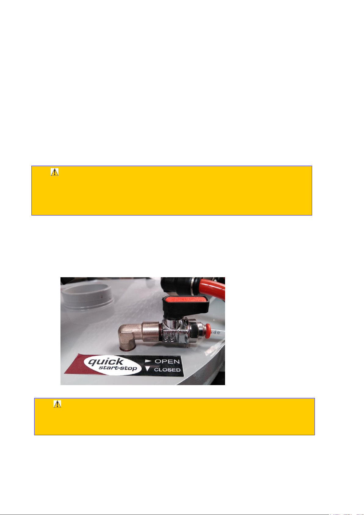
7.5. CONTROL OF THE ABRASIVE OUTLET ON LEAVING SANDING
The sandblaster has a valve in the tank cover [Exploded View 2 - Posic.94] to control
the abrasive outlet when the trigger is released.
In normal operation, the valve must be open to prevent the appearance of abrasive jets
when starting to sand and at the end.
WARNING:
Do not dismantle the regulation screw with the equipment on. Once the maximum
flow rate is reached, you must not keep turning the regulation screw [Spare parts 1 –
Posit.7] to opening, as it could be accidentally dismantled.
WARNING:
If for safety, it is necessary that the abrasive stops immediately when the trigger is
released. It is necessary, lock the key on the tank cover [Exploded view 2 - Posic.94].

SANDBLASTER 0701AREN10MAS
11
8. COMPONENTS DISMANTLE
Next, we describe how to procceed to tasks related with dismantling or substitution of
equipment components that, to EUROPE PROJECTION´s discretion, are considered
usual and can be made by the user.
To do other types of dismantling actions, it is neccessary to count on your SAT- Official
Technical Service
8.1. TIPS DISMANTLE
To dismantle the tip of the gun [Spare parts 2 –Posit.28]to clean it or substitute, you must
proceed as follows:
To disconnect the equipment from the air pressure feeding.
To unscrew the tip nut [Spare parts 2 –Posit.51]out of the adaptor [Spare parts 2 –
Posit.50] attached to the product hose.
To quit the tip [Spare parts 2 –Posit.52] out of the tip nut [Spare parts 2 –Posit.51].
To place the tip, you must do the steps below vice versa.
8.2. PRODUCT HOSE DISMANTLE
To dismantle the product hose [Spare parts 2 –Posit.28], to clean it or substitute it, you
must do the following.
To disconnect the equipment from the air pressure feeding.
To loose the clamp [Spare parts 2 –Posit.25]which fix the hose [Spare parts 2 –Posit.28] to
coupling nut [Spare parts 2 –Posit.24].
To separate the hose from the coupling nut.
To assemble again the hose, you must do the steps below vice versa.
8.3. TANK TOP DISMANTLE
This operation must be only done for maintenance and periodical cleaning. Abrasive
product loading must be done through the product loading cap [Spare parts 2 –Posit.13] and not
through the tank top [Spare parts 2 –Posit.2].
To dismantle the tank top [Spare parts 2 –Posit.2], you must do as follows:
To disconnect the equipment from the air pressure feeding.

INSTRUCTIONS AND MAINTENANCE MANUAL
12
To assure of tank is depressurized by checking manometer [Spare parts 1 –Posit.19]
placed in the regulation box of the equipment [Spare parts 1 –Posit.4].
To unscrew and remove the screws [Spare parts 2 –Posit.8] joining the top to the body
tank.
To disconnect the air feeding tube to the tank of the swivel elbow [Spare parts 2 –
Posit.64] placed on the tank top [Spare parts 2 –Posit.2] and the air tube [Despiece 2 –
Posic.84] of the valve [Despiece 2 –Posic.94] located on the tank cover [Despiece 2 –
Posic.2].
To remove the top [Spare parts 2 –Posit.2].
To assemble again the tank top, you must do the steps below in contrary sense,
paying attention to contact surfaces between the tank top and upper border are clean and free
or particles causing lack of air tightness on the locking or unnecessary joint wear [Spare parts 2 –
Posit.4].
9. PIECES OF ADVICE TO AVOID INAPPROPIATE AND DANGEROUS
PRACTICES
You must follow attentively the following warnings in order to avoid risk which can be
dangerous for people, animal or goods.
WARNING:
Do not use the equipment in the presence of other people not wearing protection
equipment and suitable clothing. The user and other people near working areas must
protect themselves from impact of abrasive product.
WARNING:
An inappropriate application of the jet of abrasive product can be dangerous. Never
point the gun to people, animals, electricity system or sandblasting equipment.
WARNING:
Never use the equipment to treat a piece hold by other user.
WARNING:
Do not make pressure against the product inlet top whereas the tank is pressurized.
To avoid accidental opening, the plastic cap [Spare parts 1 –Posit.17] must be always
placed.
WARNING:
Before doing any operation on the equipment (repairs, maintenance, elements
substitution), you must disconnect the equipment from the air pressure feeding.
WARNING:
While the equipment is working, the plastic top on the lid [Spare parts 1 –Posit.17]
must be always removed as if during the loading process, some abrasive remains on
the loading inlet (see point 7.2 “TANK LOADING”), the pressurization would be
correct and the compressed air could take out the top of the loading inlet [Spare parts
1 –Posit. 3] strongly.

SANDBLASTER 0701AREN10MAS
13
The equipment user must wear a protection screen and safety gloves. Any part of the
body must be exposed to the impact of abrasive product on the treated surface. If required
due to the sound level conditions on the working area, the user must wear hearing
protection.
The equipment must be as far as possible from working area.
The equipment can only be used by staff knowing the content of this manual.
The equipment can not be used by children or non qualified staff.
You must take special care of the abrasive product hose (no fold, no step on, no scratch
no contact with sharp objects).
Do not start the equipment without assure that hose connections to equipment and
compressor are correct.
Do not operate, fix or block the pneumatic remote control.
Use exclusively original spare parts.
Do not use the equipment under alcohol, narcotics or medicines influence.
Never open the equipment tank whereas it is pressurized.
Do not use safety valve to depressurize the tank. To depressurize, you only have to stop
acting the gun trigger.
In order to keep the air compressor in good conditions, it must be located far enough from
the sandblaster and always out of the working area.

INSTRUCTIONS AND MAINTENANCE MANUAL
14
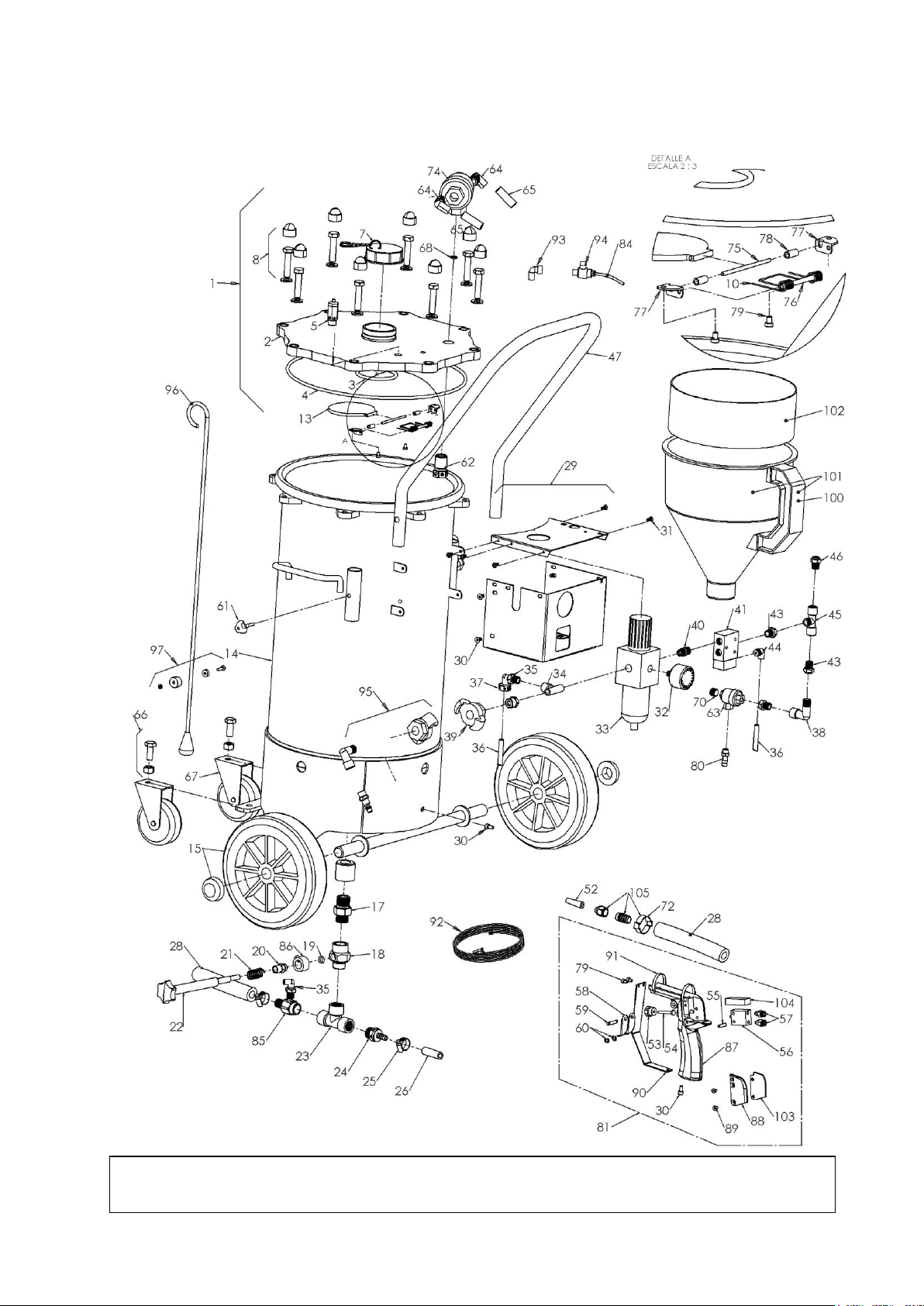
10. COMPLETE SPARE PARTS DISMANTLE
You can here find a table and graphical scheme of the components you can acquire as
original spare parts:
Model: 0701AREN30MAS
Posit.
Reference
Denomination
1
52205
MANTLED TOP
2
52097
FINISHED TOP
3
550571B
LOADING CAP TORIC JOINT
4
52080B
TOP JOINT
5
55021B
SAFETY VALVE
7
52093
COMPLETE CAP
8
52095
COMPLETE SCREWS KIT (8 Units)
10
52004B
SPRING (2 Units)
13
52026MB
MECHANIZED LOADING CAP
14
52CUERAREN30MASB
WELDED BODY ARENADORA
15
55041B
FIX WHEEL (2 Units)
17
52052B
SWIVEL NUT ½
18
52187B
REGULATOR BODY
19
52184B
JOINT (1 Unit)
20
52188B
MEDIUM PIECE
21
52019B
SPRING
22
52189B
PRODUCT OUTLET REGULATOR
23
52049B
“T” 1/2H-1/2H-1/2H
24
52020B
COUPLING NUT 1/2M DOWEL 9
25
30151B
CLAMP (2 Units)
26
52106B
HOSE 8 x 15 BLACK
28
52218
HOSE 13X25 (5m)
29
52060
COMPLETE BOX
30
52011B
ALLEN SCREW (4 Units)
31
52010B
METAL SHEET SCREW (4 Units)
32
52181B
MANOMETER 0-10 BAR 4
33
52180B
PURIFIER REGULATOR FILTER 1/4H
34
52178B
“T” 1/4M-1/4H-1/4M
35
52013B
SWIVEL ELBOW 1/4 A 4
36
52108
POLIAMIDE DOUBLE PIPE 2X4
37
52065B
PLASTIC CLAMP (10 Units)
38
55051B
ELBOW 90º 1/4M –1/4H
39
52177B
EXPRES COUPLING NUT
40
55009
COUPLING NUT 1/4M (5 UD.)
41
52014B
VALVE 3/2
43
11051/41/4H
REDUCTIÓN 1/4M –1/4H
44
52015B
SWIVEL ELBOW 1/8 A 4
45
52012B
CENTRAL “T” 1/4H-1/4M-1/4H
46
52090B
COUPLING NUT 1/4 A 10
47
52190
CARRIAGE HANDLE WITH CLAMP
52
520243B
TIP 3
53
52043B
MEDIUM NUT
54
52044B
PUSHER
55
52022B
VALVE
55
52045B
MEDIUM PIN
56
52022B
VALVE

SANDBLASTER 0701AREN10MAS
15
57
52023B
COUPLING NUT M5 TO PIPE 4
58
50068B
TRIGGER
59
50067
TRIGGER PIN ASSEMBLY (10 Units)
60
50006
SEJER RING ASSEMBLY (10 Units)
61
52207
HANDLE CLAMP
62
52103B
AIR DISTRIBUTOR
63
52073B
FAST DISCHARGE VALVE 1/8
64
52088B
SWIVEL ELBOW 1/2 A 10
65
52089B
POLYURETHANE PIPE 8x10
66
55313B
COMPLETE SCREWS KIT FOR ROTATING WHEEL (2UD)
67
55042B
ROTATING WHEEL (1UD)
68
52104B
52104B
70
55258B
CAP 1/8
71
10M91BLISTER
ADAPTATOR 1/4H (2 UD.)
72
52168B
CLAMP 25 x 28
74
52087B
FAST DISCHARGE VALVE 1/2
75
52115B
FILLING LID AXLE
76
52116B
SPRING AXLE FILLING LID
77
52113B
FILLING LID BRACKET KIT
78
52117B
FILLING LID BUSHING
79
52114B
SCREW M4X6 (2 U.)
80
10M92BLISTER
ADAPTATOR 1/8M (2 Units)
81
52110
COMPLETE GUN SET
84
52214
POLYAMIDE TUBE 2x4 (1,5 m.)
85
52166B
COUPLING CONNECTOR ½ SPIKE 13
86
52172B
TOP REGULATOR PRODUCT+SCREW
87
52JAFEARENCUERPOB
SANSBLASTER GUN BODY
88
52JAFEARENTAPAB
SANDBLASTER GUN BODY CAP
89
52169B
STAINLESS COUNTERSUNK HEAD SCREW M4x8
(2 Units)
90
52167B
SANDBLASTER GUN PROTECTOR
91
23VAKRT556011
50 PLASTIC CLAMP 250x5
92
52215
GROUND WIRE + CLAMP (PIN)
93
52179B
ELBOW 1/8
94
52182B
VALVE 1/4 TUBE 4
95
52210
ADAPTATOR EXPRES CR 3/8
96
52195
LOAD METER
97
52211
SUPPORT FOR LOAD METER
100
50160ASA
HANDLE
101
52062
FUNNEL
102
52TAMIZ
SIEVE
103
52231B
COVER FOAMS
104
52233B
VALVE FOAMS
105
52236B
TIP HOUSING SET
Table 5
INSTRUCTIONS AND MAINTENANCE MANUAL
16
Spare parts 2 –Repairing components (0701AREN30MAS) (Rev1)

SANDBLASTER 0701AREN10MAS
17
TROUBLESHOOTING
ANOMALY
POSSIBLE CAUSE
CHECKING POINTS
SOLUTION
I. No air through the
tip
A) Compressor unplugged or
switched off
Feeding compressor
To connect the compressor to
sandblaster and start it
B) Tip clogged up
Tip
To dismantle gun tip and blow it to
remove obstruction
C) Sand flow rate regulator
too open
Outlet product regulator
To close the regulator until reach
the appropiate opening level. To
blow the hose and the tip.
D) Excessive granule
diameter of used abrasive
Abrasive
To empty the tank and fill it with
abrasive with sutiable diameter. To
blow the hoses to remove residual
abrasive.
E) Product hose clogged up
Product hose
To dismantle product hose and
clean
F) Three via valve placed in
regulation box doesn´t
work
Three via valve
Substitute
G) Gun valve doesn´t work
Gun valve
Substitute
II. No abrasive
through gun (only
air)
A) Tank without abrasive
Tank
To load tank with abrasive product
B) Outlet abrasive clogged up
Product outlet
To operate regulation handle to
increase flow rate
To clean tank outlets piping
C) Excessive granule
diameter of used abrasive
Abrasive
To empty the tank and fill it with
abrasive with suitable diameter. To
blow the hoses to remove residual
abrasive.
D) Outlet abrasive reguladtor
closed
Outlet product regulator
To operate regulation handle to
increase flow rate
III. Non uniform
abrasive flow
A) Wet abrasive or foreign
particles
Tank interior
To empty tank and load it with dry
and filtered abrasive.
B) Excessive granule
diameter of used abrasive
Abrasive
To empty the tank and fill it with
abrasive with suitable diameter. To
blow the hoses to remove residual
abrasive.
C) Sand flow rate regulator
too open
Outlet product regulator
To operate the regulator until reach
the appropiate opening level.
IV. The result of the
application is not
satisfactory
A) Inappropiate tip for the
application
Tip
To substitute the tip (according to
Table 1)
B) Lack of air tightness of the
hoses
Hoses
To substitute the hoses
C) Inappropiate working
pressure
Pressure regulador
To operate on the air regulator until
get the resulted wanted
C) Inappropiate abrasive to
the work to be done
Abrasive
To ask for information to your
abrasive supplier about the most
recommended product for each
work
V. Air exhaust by
safety valve
A) Excessive air pressure of
the compressor feeding
the sandblaster
Manometer of the
compressor
To regulate outgoing air pressure
on compressor up to a maximum 6
kg/cm²
VI. Inadequate air
going out through
tip
A) Purifier filter clogged up
Purifier filter
To clean purifier filter
B) Tip clogged up in the part
of the hose
Tip - hose
To disconnect the hose from the
sandblaster and blow from tip to
unblock it.

INSTRUCTIONS AND MAINTENANCE MANUAL
18
ANOMALY
POSSIBLE CAUSE
CHECKING POINTS
SOLUTION
VII. Lack o fair
tightness on tops
A) Existence of foreign
particles which hinders
the air tightness of those
ones
Tops
To clean surfaces in contact with
tops
B) Worn or damaged joints
Joints
To substitute
VII. Block of gun
trigger
A) Lack of lubrication
Gun trigger
To lubricate and clean the gun
trigger periodically
B) Lack of cleaning
Table 6
12. EQUIPMENT STORAGE
In case that the equipment is not going to be used for a long time, it is recommended
to store according to the following instructions:
To disconnect the equipment of any feeding source.
To empty the tank.
To clean completely the tank and remove any waste or sediment inside.
To cover the equipment with a waterproof package.
13. EQUIPMENT WITHDRAW
Once useful life of the equipment is ended, you must follow some basic rules of
behaviour to withdraw in a environment-friendly way.
The packages, the flexible pipes, the plastic components and non-metallic components
must be dismantled and removed separately.
14. INSPECTIONS AND PERIODICAL TESTS
According to current regulations on pressure equipments in the fabrication date, the
equipment must be subject every 10 years, at least, to a visual inside and outside inspection
and a pressure test.
Test and inspections must be done according to the specific regulation on pressure
equipment of the country where the equipment is used.
Annually the equipment will be cleaned thoroughly in the inside by the equipment user.
The safety valve will be subject, at least, to a checking every year, to be done by the
user.
However, once read the before exposed, it is responsibility of the user to be updated
on current regulations on pressure equipments for the useful life of the equipment and make
inspections and periodical tests specified on these ones.

DECLARATION OF CONFORMITY
AUTHORIZED REPRESENTATIVE:
EUROPE PROJECTION
228, avenue Olivier Perroy
13790 ROUSSET
DECLARES THAT THE EQUIPMENT DESIGNATED BELOW:
Model : MINI-SABLEUSE 30 L
Reference : 70475
COMPLIES WITH THE STANDARDS:
• UNE-EN 13445
ROUSSET, JANUARY 20th 2020
Patrick BOREL
President
EUROPE PROJECTION - 228, avenue Olivier Perroy 13790 ROUSSET
Tél : +33 (0)4 42 29 08 96 – Fax : +33 (0)4 42 53 44 36
SAS au capital de 400 000 € - RCS Aix-en-Provence B 394 961 510 - NAF 2892 Z - Intracom : FR 54 394 961 510

EUROPE PROJECTION - 228, avenue Olivier Perroy 13790 ROUSSET - Tél : +33 (0)4 42 29 08 96 – Fax : +33 (0)4 42 53 44 36
SAS au capital de 400 000 € - RCS Aix-en-Provence B 394 961 510 - NAF 2892 Z - Intracom : FR 54 394 961 510
Table of contents
Other EUROPRO Power Tools manuals

Popular Power Tools manuals by other brands


Labounty
Labounty MSD Series Safety, Operation & Maintenance

RED ROOSTER
RED ROOSTER RRI-60SA manual

GRAVEDA
GRAVEDA GRASPRESSO GP4-20 instruction manual
 manual")
Trumpf
Trumpf TruTool F 300 (3B1) manual

Festool
Festool OF 2200 EB Supplemental user's manual

Powers Fasteners
Powers Fasteners P35s Operating instructions manual