Unit 6, St Martin’s Park
Moorend Farm Avenue
Cabot Park, Avonmouth
Bristol, BS11 0RS
Tel: +44 (0)1179 381800
Fax: +44 (0)1179 381801
Web: www.sdsdrives.com
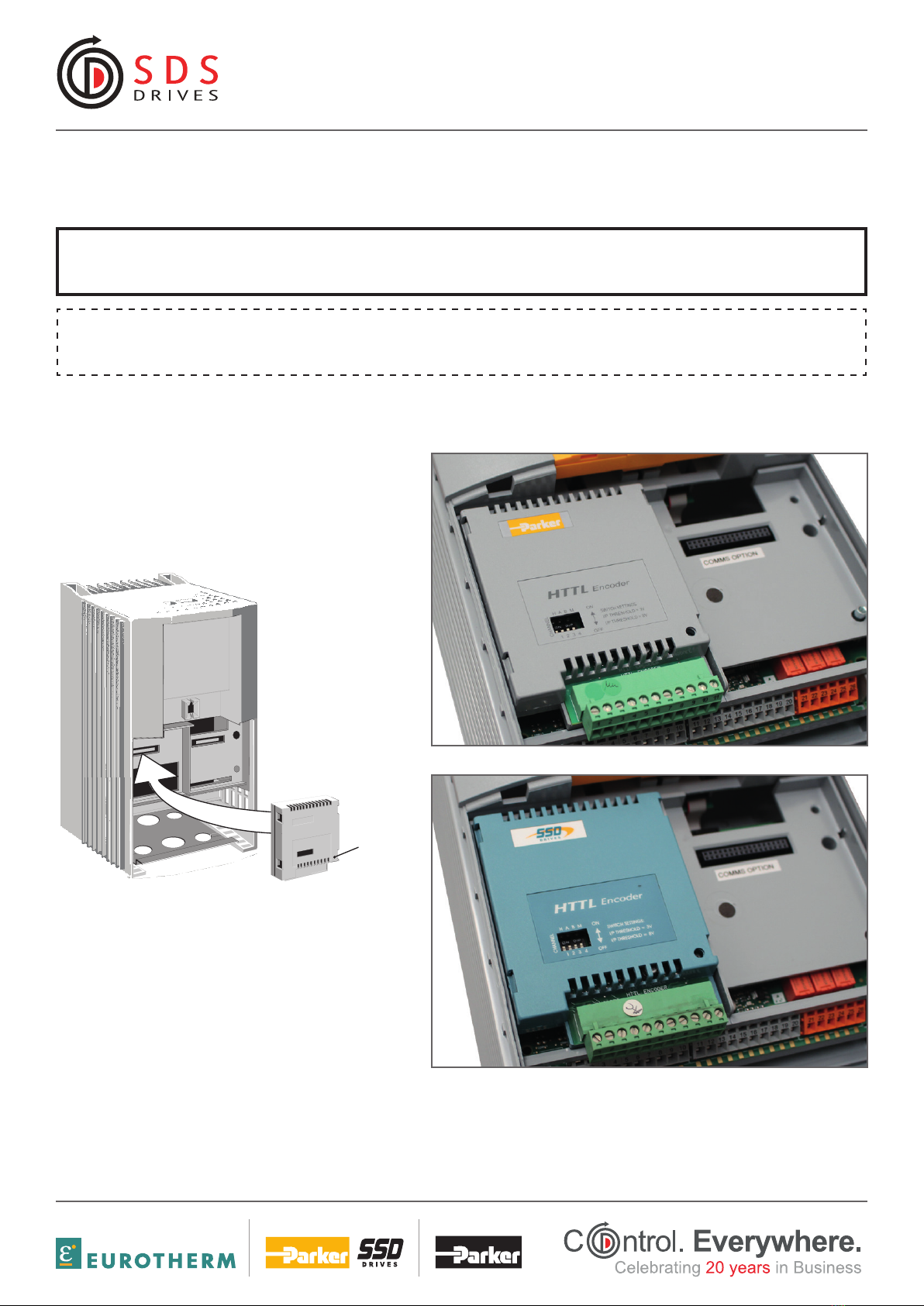
formerly now
then
For correct operation, A, /A, B and /B must be connected as shown. If any is left unconnected, the HTTL speed feedback
technology box will not operate.
Note: The M and H inputs are not normally connected - these are for use with future versions of drive software.
M: For connection to the once-per-revolution marker output from the encoder to verify correct operation of the encoder.
H: For where the encoder has provision for a `health’ output.
Take special care wiring the encoders to the option due to the low level of the signals.
All wiring to the HTTL Speed Feedback Technology Box should be made in screened cable. Use cable with an overall screen and a
screen over each individual pair. To ensure compliance with the EMC Directive the overall cable screen should be connected to the
encoder body and to the terminal block, pin 11.
Recommended cable (pairs individually screened):
Belden equivalent 8777
SSD Drives Part Number CM052666
Terminal Block (TB1) Connections
3
HTTL Speed Feedback Technology Box
DIP Switch Settings
The DIP switch can be seen
through the casing of the
HTTL Speed Feedback
Technology Box.
The switch settings control
the following inputs:
Usually the switches will be set to give a threshold of 3V when using a differential encoder, and
to 8V when using a single-ended encoder. (Factory default is with switches 1 & 2 set in the ON
position - 3V).
Terminal Block (TB1) Connections
For correct operation, A, /A, B and /B must be connected as shown. If any is left unconnected,
the HTTL speed feedback technology box will not operate.
Note: The M and H inputs are not normally connected - these are for use with future versions
of drive software.
M: For connection to the once-per-revolution marker output from the encoder to verify
correct operation of the encoder.
H: For where the encoder has provision for a `health’ output.
Take special care wiring the encoders to the option due to the low level of the signals.
All wiring to the HTTL Speed Feedback Technology Box should be made in screened cable.
Use cable with an overall screen and a screen over each individual pair. To ensure compliance
with the EMC Directive the overall cable screen should be connected to the encoder body and to
the terminal block, pin 11.
Recommended cable (pairs individually screened):
Belden equivalent 8777
Parker SSD Drives Part Number CM052666
1234
ON
OFF
DIP SWITCH
TB1
DIP
Input Threshold
Switch Number 1 2 3 4
Input Controlled H A B M
3V±1 On On On On
8V±1 Off Off Off Off
2
134 56 78910 11
TB1 - TECHNOLOGY BOX
GND
M /MH /H A /A B /B +-
supply
0V
M
HA B+-
supply
ENCODER
Figure 2 Single-Ended Encoder Outputs
2
134 56 78910 11
TB1 - TECHNOLOGY BOX
GND
M /MH /H A /A B /B +-
supply
0V
M
HA B+-
supply
/M
/B/A
/H
ENCODER
Figure 3 Differential Encoder Outputs
This manual was downloaded at: www.sdsdrives.com
+44 (0)117 938 1800
Figure 3 Differential Encoder Outputs Figure 2 Single-Ended Encoder Outputs
DIP Switch Settings
The DIP switch can be seen
through the casing of the
HTTL Speed Feedback
Technology Box.
The switch settings control
the following inputs:
3
HTTL Speed Feedback Technology Box
DIP Switch Settings
The DIP switch can be seen
through the casing of the
HTTL Speed Feedback
Technology Box.
The switch settings control
the following inputs:
Usually the switches will be set to give a threshold of 3V when using a differential encoder, and
to 8V when using a single-ended encoder. (Factory default is with switches 1 & 2 set in the ON
position - 3V).
Terminal Block (TB1) Connections
For correct operation, A, /A, B and /B must be connected as shown. If any is left unconnected,
the HTTL speed feedback technology box will not operate.
Note: The M and H inputs are not normally connected - these are for use with future versions
of drive software.
M: For connection to the once-per-revolution marker output from the encoder to verify
correct operation of the encoder.
H: For where the encoder has provision for a `health’ output.
Take special care wiring the encoders to the option due to the low level of the signals.
All wiring to the HTTL Speed Feedback Technology Box should be made in screened cable.
Use cable with an overall screen and a screen over each individual pair. To ensure compliance
with the EMC Directive the overall cable screen should be connected to the encoder body and to
the terminal block, pin 11.
Recommended cable (pairs individually screened):
Belden equivalent 8777
Parker SSD Drives Part Number CM052666
1234
ON
OFF
DIP SWITCH
TB1
DIP
Input Threshold
Switch Number 1 2 3 4
Input Controlled H A B M
3V±1 On On On On
8V±1 Off Off Off Off
2
134 56 78910 11
TB1 - TECHNOLOGY BOX
GND
M /MH /H A /A B /B +-
supply
0V
M
HA B+-
supply
ENCODER
Figure 2 Single-Ended Encoder Outputs
2
134 56 78910 11
TB1 - TECHNOLOGY BOX
GND
M /MH /H A /A B /B +-
supply
0V
M
HA B+-
supply
/M
/B/A
/H
ENCODER
Figure 3 Differential Encoder Outputs
This manual was downloaded at: www.sdsdrives.com
+44 (0)117 938 1800
Usually the switches will be set to give a threshold of 3V when using a differential encoder, and to 8V when using a single-ended
encoder. (Factory default is with switches 1 & 2 set in the ON position - 3V).
3
HTTL Speed Feedback Technology Box
DIP Switch Settings
The DIP switch can be seen
through the casing of the
HTTL Speed Feedback
Technology Box.
The switch settings control
the following inputs:
Usually the switches will be set to give a threshold of 3V when using a differential encoder, and
to 8V when using a single-ended encoder. (Factory default is with switches 1 & 2 set in the ON
position - 3V).
Terminal Block (TB1) Connections
For correct operation, A, /A, B and /B must be connected as shown. If any is left unconnected,
the HTTL speed feedback technology box will not operate.
Note: The M and H inputs are not normally connected - these are for use with future versions
of drive software.
M: For connection to the once-per-revolution marker output from the encoder to verify
correct operation of the encoder.
H: For where the encoder has provision for a `health’ output.
Take special care wiring the encoders to the option due to the low level of the signals.
All wiring to the HTTL Speed Feedback Technology Box should be made in screened cable.
Use cable with an overall screen and a screen over each individual pair. To ensure compliance
with the EMC Directive the overall cable screen should be connected to the encoder body and to
the terminal block, pin 11.
Recommended cable (pairs individually screened):
Belden equivalent 8777
Parker SSD Drives Part Number CM052666
1234
ON
OFF
DIP SWITCH
TB1
DIP
Input Threshold
Switch Number 1 2 3 4
Input Controlled H A B M
3V±1 On On On On
8V±1 Off Off Off Off
2
134 56 78910 11
TB1 - TECHNOLOGY BOX
GND
M /MH /H A /A B /B +-
supply
0V
M
HA B+-
supply
ENCODER
Figure 2 Single-Ended Encoder Outputs
2
134 56 78910 11
TB1 - TECHNOLOGY BOX
GND
M /MH /H A /A B /B +-
supply
0V
M
HA B+-
supply
/M
/B/A
/H
ENCODER
Figure 3 Differential Encoder Outputs
This manual was downloaded at: www.sdsdrives.com
+44 (0)117 938 1800