manuals.online logo
Brands
  1. Home
  2. •
  3. Brands
  4. •
  5. Danfoss
  6. •
  7. Control Unit
  8. •
  9. Danfoss BVTS User manual

Danfoss BVTS User manual

Installation guide
Thermostatic valve
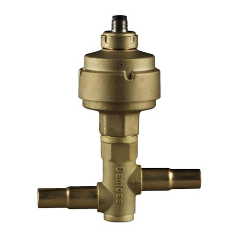
Type BVTS
© Danfoss A/S (AC-MCI / jmn), 2013-11 IC.PI.500.E5.72 / 520B5748 1
003R9003
003R9003
Dansk
English
P
max. 10 bar
Fig. 1 Fig. 2 Fig. 3
0035
PED 97/23/EC cat. IV
EN 14597 (DIN 3440)
Application
The thermostatic valve BVTS is designed for
protection of biomass boilers and re stoves.
It prevents overheating of the boiler by
discharging water from heat generator or
condensing coil.
The valve is used also to prevent
back-burning in the fuel store by ooding
the fuel in case of excessive temperature.
Technical Data
Media: Water
Opening temperature: 95 °C ± 2 °C
(xed)
Max. sensor temperature: 125 °C
Flow capacity: 2.6 m3/h
(∆p = 1bar)
Connection size: G ¾ pipe thread
(ISO-228)
Dimensions in [mm], (g. 1)
Installation
Installation of BVTS valve on boiler with
safety heat exchanger A (g. 2).
Installation of BVTS valve in back-burning
application B (g. 2) .
Before installation of the valve ush the
system to make sure that there are no
impurities which might deposit on the valve
seat and cause malfunction.
Remember to install a lter ahead of the
valve. (Fig. 3).
The sensor can be mounted in any position.
Make sure the whole sensor is in contact
with the controlled area.
The arrow on the valve body shows
direction of ow. When installing the valve,
make sure it is positioned properly.
Max torque for sensor pocket mounting is
30 Nm.
Only cooling applications:
After installation the proper function of the
valve should be checked by heating up the
system.
Service
It is recommended to check proper function
of the valve once a year by qualied
personnel. Functional check is carried out
manually by depressing the red button that
opens the ow on the valve.
It is not allowed to lose red button as it will
cause product malfunction.
Tekniske data
Medier: Vand
Åbningstemperatur: 95 °C ± 2 °C (fast)
Maks. følertemperatur: 125 °C
Flowkapacitet: 2.6 m3/h
(∆p = 1bar)
Tilslutningsstørrelse: G ¾ Rørgevind
(ISO-228)
Dimensioner [mm], (g. 1)
Installation
Installation af BVTS-ventilen på kedel med
sikkerhedsvarmeveksler A (g. 2).
Installation af BVTS-ventil som
brandbeskyttelse B (g. 2).
Før installation af ventilen skal systemet
skylles igennem for at sikre, at der ikke
ndes urenheder, der kan aejres på
ventilsædet og forårsage fejlfunktion.
Husk at installere et lter foran ventilen.
(Fig. 3).
Føleren kan installeres i en hvilken som
helst position. Sørg for, at hele føleren er
i kontakt med det kontrollerede område.
Pilen på ventilenheden viser owets
retning. Når ventilen installeres, skal sikres,
at den er placeret korrekt. Maks. moment
for føler lomme er 30Nm.
Kun køleformål:
Efter installation skal ventilens korrekte drift
kontrolleres ved at varme systemet op.
Service
Det anbefales, at kvaliceret personale en
gang om året kontrollerer ventilens korrek-
te drift. Funktionel kontrol udføres manuelt
ved at trykke på den røde knap, som åbner
owet på ventilen.
Forskruningen der holder den røde test
knap, må ikke løsnes, da dette vil medføre
funktionsfejl.
ø16
B
A
Anvendelse
Den termostatiske ventil BVTS er konstrueret
til beskyttelse af biomassekedler og
brændeovne. Den forhindrer overhedning af
kedlen ved at udlede vand fra varmege
neratoren eller kondensatorspolen.
Ventilen anvendes også til at undgå brand
i brændstoageret ved at oversprøjte
brændstoet med vand, hvis temperaturen
bliver for høj.
2 IC.PI.500.E5.72 / 520B5748 © Danfoss A/S (AC-MCI / jmn), 2013-11
Espagñol
Francais
Deutsh
Anwendung
Das thermostatisch gesteuerte Ventil BVTS
ist für den Schutz von Biomassekesseln und
Brennöfen ausgelegt.
Durch das Ablassen von Wasser aus dem
Wärmeerzeuger oder der Kondensator-
schlange wird eine Überhitzung vermieden.
DasVentil bietet weiterhin Rückbrandschutz
im Brennstobehälter, indem es bei zu
hoher Temperatur önet und so Wasser auf
den Brennsto gesprüht wird.
Technische Daten
Medien: Wasser
Önungstemperatur: 95 °C ± 2 °C (fest)
Max. Fühlertemperatur: 125 °C
Strömungsleistung: 2.6 m3h
(∆p = 1bar)
Anschlussgröße: G¾ Rohrgewinde
(ISO-228)
Maße [mm], (Abb. 1)
Installation
Installation des BVTS-Ventils
in Kesselanwendungen mit
Sicherheitswärmetauscher A (Abb. 2).
Installation des BVTS-Ventils in
Anwendungen mit
Rückbrandgefahr B (Abb.2).
Vor der Installation des Ventils muss
das System gespült werden. So wird
vermieden, dass sich Verunreinigungen am
Ventilsitz ablagern und eine Fehlfunktion
verursachen.
Vor dem Ventil ist ein Filter
anzubringen (Abb. 3).
Der Fühler kann in einer beliebigen Position
montiert werden. Es ist darauf zu achten,
dass der Fühler mit dem zu überwachenden
Bereich in Kontakt ist.
Der Pfeil auf dem Gehäuse gibt die
Durchussrichtung an. Bei der Installation
des Ventils ist auf die ordnungsgemäße
Ausrichtung zu achten.
Max Drehmoment für das Tauchrohr ist
30 Nm.
Hinweis für Kühlanwendungen:
Nach der Installation ist die
ordnungsgemäße Funktion des Ventils zu
prüfen. Dazu ist das System aufzuheizen.
Wartung
Die ordnungsgemäße Funktion des Ventils
ist einmal jährlich durch einen geschulten
Techniker zu überprüfen. Die
Funktions-prüfung erfolgt manuell durch
Drücken des roten Knopfs. Dadurch wird
das Ventil geönet und der Durchuss
eingeleitet.
Die Mutter, die den roten Knopf befestigt,
darf nicht gelöst werden, da dies eine
Funktionsstörung verursachen kann.
Application
La vanne thermostatique BVTS a été conçue
pour assurer la protection des chaudières à
biomasse et des poêles.
Elle empêche la surchaue de la chaudière
en déchargeant l’eau du générateur de
chaleur ou du serpentin de condensation.
Cette vanne sert également à éviter un
retour de amme dans le réservoir de
combustible en noyant celui-ci en cas de
température excessive.
Caractéristiques techniques
Fluide: Eau
Température d’ouverture : 95˚C ± 2 °C
(xe)
Max. température de la sonde: 125 °C
Capacité d´écoulement: 2.6 m3/h à
(∆p = 1bar) Taille du
raccord: Filetage
tuyau G ¾
(ISO-228)
Dimensions [mm], (g. 1)
Installation
Installation de la vanne BVTS sur la
chaudière avec un échangeur de chaleur de
sécurité A (g. 2).
Installation de la vanne BVTS dans
l’application anti-retour de amme B (g. 2).
Avant d’installer la vanne, rincer le système
an de garantir l’absence d’impuretés
susceptibles de se déposer sur le
siège de la vanne et de provoquer des
dysfonctionnements.
Penser à installer un ltre en amont de la
vanne. (Fig. 3)
La sonde peut être placée dans n’importe
quelle position. Veiller à ce que la sonde
complète soit au contact de la zone
contrôlée.
La èche indiquée sur le corps de vanne
indique le sens d’écoulement. Lors de
l’installation de la vanne, vérier sa position.
Le couple maximal de serrage pour le
montage de la poche à bulbe est de 30
Nm.
Applications de refroidissement seul :
Après l’installation, le bon fonctionnement
de la vanne doit être vérié en chauant le
système.
Entretien
Il est recommandé de faire vérier le bon
fonctionnement de la vanne une fois par an
par une personne qualiée. La vérication
se fait manuellement en appuyant sur le
bouton rouge qui actionne l’ouverture de
la vanne.
L’écrou attachant le bouton rouge ne
doit pas être desserré ou cela causera un
mauvais fonctionnement de la vanne.
Aplicación
La válvula térmostatic BVTS se ha diseñado
para proteger calderas de biomasa y estufas.
Impide el sobrecalentamiento de la caldera
al vaciar el agua del termogenerador o la
bobina del condensador.
La válvula se utiliza también para impedir
incendios en el depósito de combustible,
por la inundación del combustible.
Datos técnicos
Medio: Agua
Tempratura de apertura: 95 ˚C ± 2 °C
(jos)
Temperatura del sensor: 125 ˚C
Capacidad de ujo: 2.6 m3/h
(∆p = 1bar)
Tamaño de conexión: Conexión
roscada G ¾
(ISO-228)
Dimensiones [mm]
Instalación
Instalación de la válvula BVTS en una caldera
con intercambiador de calor de seguridad
A (g. 2).
Instalación de la válvula BVTS en un sistema
contra incendios B (g. 2).
Antes de proceder con la instalación de la
válvula, limpie el sistema para asegurarse de
que no han quedado impurezas que puedan
depositarse en el asiento de la válvula y
provocar un mal funcionamiento.
No olvide instalar un ltro delante de la
válvula (g. 3).
El sensor puede instalarse en cualquier
posición. Asegúrese de que todo el sensor
esté en contacto con el área controlada.
La echa en el cuerpo de la válvula
muestra la dirección del ujo. Al instalar
la válvula, compruebe que esté colocada
correctamente.
El par de apriete máx. para el sensor
montado, es 30 Nm.
Solo sistemas de refrigeración:
Tras la instalación debe comprobarse que la
válvula funciona correctamente calentando
el sistema.
Servicio
Se recomienda que personal cualicado se
encargue de comprobar el funcionamiento
correcto de la válvula una vez al año.
La comprobación funcional se efectúa
manualmente pulsando el botón rojo que
abre el ujo en la válvula.
La tuerca que sujeta el botón rojo, no
debe soltarse, ya que podría causar un mal
funcionamiento.
© Danfoss A/S (AC-MCI / jmn), 2013-11 IC.PI.500.E5.72 / 520B5748 3
Italiano Polski Czech
Applicazione
La valvola termostatica BVTS è progettata
per la protezione di caldaie a biomassa e
forni.
Evita il surriscaldamento della caldaia
scaricando acqua dal generatore di calore o
dalla batteria di condensazione.
La valvola BVTS si utilizza anche per
impedire il ritorno di amma nel serbatoio
del combustibile immettendo acqua in caso
di temperatura eccessiva.
Dati tecnici
Fluido: Acqua
Temperatura di apertura: 95 ˚C ± 2 °C (ssa)
Temperatura sensore: 125 ˚C
Capacità di usso: 2.6 m3/h
(∆p = 1bar)
Dimensioni attacco: Filettatura tubo
G ¾ (ISO-228)
Dimensioni [mm], (g. 1)
Installazione
Installazione della valvola BVTS sulla caldaia
con scambiatore di calore di sicurezza A
(g. 2).
Installazione della valvola BVTS per
prevenire il ritorno di amma B (g. 2).
Prima di installare la valvola, lavare il sistema
per assicurare che non vi siano impurità che
possono depositarsi sulle parti della valvola,
causandone il cattivo funzionamento.
Ricordare di installare un ltro a monte della
valvola. (Fig. 3).
Il sensore può essere montato in qualsiasi
posizione. Assicurarsi che tutto il sensore sia
in contatto con l’area tenuta sotto controllo.
La freccia sul corpo della valvola indica la
direzione del usso.
Installando la valvola, assicurarsi che questa
sia posizionata in modo corretto.
Massima coppia di serraggio per il pozzeto
del sensore 30 Nm.
Solo applicazioni di rareddamento:
Dopo l’installazione, vericare il corretto
funzionamento della valvola riscaldando il
sistema.
Manutenzione
Si raccomanda di vericare annualmente
il corretto funzionamento della valvola,
tramite personale qualicato. La prova
funzionale viene eettuata manualmente
premendo il pulsante rosso che apre il usso
della valvola.
Il dado di serraggio del pulsante rosso non
deve essere allentato/manomesso per non
causare il malfunzionamento della valvola.
Zastosowanie
Zawór Termostatyczny BVTS ma
zastosowanie w instalacjach grzewczych
jako zabezpieczenie dla kominków oraz
kotłów na paliwo stałe.
Zawór zapobiega przegrzaniu kotła poprzez
zrzut wody z podgrzewacza lub wężownicy
kondensacyjnej.
BVTS zabezpiecza również przed cofaniem
płomienia do podajnika paliwa stałego
poprzez zalanie paliwa w sytuacji
nadmiernego wzrostu temperatury.
Dane techniczne
Medium: woda
Temperatura otwarcia: 95 °C ± 2 °C
stała
Max. temperatura sensora: 125 °C
Przepływ: 2.6 m3/h
(∆p = 1bar)
Przyłącze: G ¾ (ISO-228)
Wymiary w [mm], (rys. 1)
Instalacja
Instalacja zaworu BVTS na kotle z
wymiennikiem chłodzącym A (rys. 2).
Instalacja zaworu BVTS jako zabezpieczenie
przed cofaniem płomienia B (rys. 2).
Przed instalacją zaworu należy przepłukać
instalację, aby upewnić się, że nie ma w niej
osadów i innych obcych materiałów, które
mogłyby osadzać się na gnieździe zaworu
powodując awarię.
Należy pamiętać o zainstalowaniu ltra
przed zaworem (rys. 3).
Czujnik może być instalowany w każdym
położeniu. Należy upewnić się, że cały
czujnik jest w kontakcie z obszarem
pomiaru. Strzałka na korpusie zaworu
pokazuje kierunek przepływu wody.
Instalując zawór należy się upewnić, że jest
on właściwie ustawiony.
Maksymalny moment dokręcający dla
kieszeni czujnika to 30 Nm.
Tylko dla instalacji z wymiennikiem:
Po zainstalowaniu należy sprawdzić
poprawne działanie zaworu przez
podgrzanie instalacji.
Obsługa serwisowa
Zalecane jest sprawdzanie poprawnego
działania zaworu raz w roku przez
wykwalikowaną obsługę.
Test przeprowadza się ręcznie wciskając
czerwony przycisk, który otwiera przepływ
przez zawór.
Nie wolno odkręcać nakrętki mocującej
przycisk testowy gdyż spowoduje to
wadliwe działanie zaworu.
Aplikace
Termostatický ventil pro chladící smyčku
BVTS je navržený k ochraně kotlů na
biomasu.
Chrání před přehříváním tím, že odvádí
vodu ze zdroje tepla nebo kondenzační
smyčky.
Při nadměrně vysokých teplotách může
ventil BVTS také zabránit zpětnému hoření
paliva v zásobníku, a to tím, že zalije palivo
vodou.
Technické údaje
Média: Voda
Počáteční teplota: 95 °C ± 2 °C
(neměnné)
Hystereze: 6 °C
Teplota prostředí: 0 a 80 °C
Maximální teplota čidla: 125 °C
Prùtok: 2,6 m3 /hod
(∆p = 1bar)
Velikost připojení: trubkový závit G ¾
(ISO-228)
Rozměry [mm], (obr. 1)
Instalace
Instalace ventilu BVTS na kotel s
bezpečnostním výměníkem tepla A (obr. 2).
Instalace ventilu BVTS na zařízení se
zpětným hořením B (obr. 2).
Před instalací ventilu systém propláchněte,
aby v něm nezůstaly žádné nečistoty,
které by se mohly usadit na sedle ventilu a
způsobit tak poruchu.
Nezapomeňte nad ventil nainstalovat ltr
(obr. 3).
Senzor lze namontovat do jakékoli pozice.
Přesvědčte se, že se senzor kontrolované
části dotýká celý.
Šipka na tělese ventilu ukazuje směr toku.
Při instalaci ventilu se přesvědčte, že je
správně umístěný.
Max. utahovací moment senzorové jímky je
30 Nm.
Pouze chladicí zařízení:
Po instalaci ventilu zahřáním systému
zkontrolujete, zda ventil pracuje správně.
Údržba
Kvalikovaný pracovník by měl jednou za
rok zkontrolovat, zda ventil pracuje správně.
Kontrola fungování se provádí ručně, a to
stiskem červeného tlačítka, které otevírá
průtok na ventilu.
Matice upevňující červené tlačítko nesmí
být povolená, protže by tím mohla
způsobovat špatnou funkci.

Other Danfoss Control Unit manuals

Danfoss PVG 32 Manual

Danfoss

Danfoss PVG 32 Manual

Danfoss EV210B Operating instructions

Danfoss

Danfoss EV210B Operating instructions

Danfoss MSV-F Plus DN 15 User manual

Danfoss

Danfoss MSV-F Plus DN 15 User manual

Danfoss CVP User manual

Danfoss

Danfoss CVP User manual

Danfoss ASV-PV User manual

Danfoss

Danfoss ASV-PV User manual

Danfoss ADAP-KOOL AK-CT 200A User manual

Danfoss

Danfoss ADAP-KOOL AK-CT 200A User manual

Danfoss Pilot-controlled PCVQ User manual

Danfoss

Danfoss Pilot-controlled PCVQ User manual

Danfoss DSV 2 User manual

Danfoss

Danfoss DSV 2 User manual

Danfoss REG-SA SS 15-40 User manual

Danfoss

Danfoss REG-SA SS 15-40 User manual

Danfoss AMZ 112 User manual

Danfoss

Danfoss AMZ 112 User manual

Danfoss PCV-VFGS 2 DN 150-250 User manual

Danfoss

Danfoss PCV-VFGS 2 DN 150-250 User manual

Danfoss Genesis Passive User manual

Danfoss

Danfoss Genesis Passive User manual

Danfoss ETS 250 User manual

Danfoss

Danfoss ETS 250 User manual

Danfoss EV251B Installation instructions manual

Danfoss

Danfoss EV251B Installation instructions manual

Danfoss ICLX 32 User manual

Danfoss

Danfoss ICLX 32 User manual

Danfoss ASV-M User manual

Danfoss

Danfoss ASV-M User manual

Danfoss ICV PM 25 User manual

Danfoss

Danfoss ICV PM 25 User manual

Danfoss AFQM User manual

Danfoss

Danfoss AFQM User manual

Danfoss PVG 120 Manual

Danfoss

Danfoss PVG 120 Manual

Danfoss VF3 DN 200 User manual

Danfoss

Danfoss VF3 DN 200 User manual

Danfoss SVA-S 6-10 User manual

Danfoss

Danfoss SVA-S 6-10 User manual

Danfoss AK-CM 102 User manual

Danfoss

Danfoss AK-CM 102 User manual

Danfoss AME 13 SU User manual

Danfoss

Danfoss AME 13 SU User manual

Danfoss VHX-DUO Installation instructions manual

Danfoss

Danfoss VHX-DUO Installation instructions manual

Popular Control Unit manuals by other brands

Risco AGM Installation and programming instructions

Risco

Risco AGM Installation and programming instructions

Toa AC-F1 operating instructions

Toa

Toa AC-F1 operating instructions

Siemens MICROMASTER 420 operating manual

Siemens

Siemens MICROMASTER 420 operating manual

Befaco LICH user manual

Befaco

Befaco LICH user manual

RF-Star RF-BM-ND04I manual

RF-Star

RF-Star RF-BM-ND04I manual

Solaronics SIGB Installation, use & maintenance manual

Solaronics

Solaronics SIGB Installation, use & maintenance manual

Genebre 2034 Installation, operation and maintenance manual

Genebre

Genebre 2034 Installation, operation and maintenance manual

Enter-Tech ED11K-TM user manual

Enter-Tech

Enter-Tech ED11K-TM user manual

Emerson Fisher 98LD instruction manual

Emerson

Emerson Fisher 98LD instruction manual

Sophos SG 210 Mounting instructions

Sophos

Sophos SG 210 Mounting instructions

Hunter PCM-1600 installation guide

Hunter

Hunter PCM-1600 installation guide

SANDIA aerospace SA 3/L/NVG installation manual

SANDIA aerospace

SANDIA aerospace SA 3/L/NVG installation manual

Z3 Technology Z3-DM8169-VI-RPS User instructions

Z3 Technology

Z3 Technology Z3-DM8169-VI-RPS User instructions

Comelit 1259C Technical manual

Comelit

Comelit 1259C Technical manual

Cavli Wireless C100QM Hardware manual

Cavli Wireless

Cavli Wireless C100QM Hardware manual

Kidde Fire Systems PEGAsys LV Installation, operation and maintenance manual

Kidde Fire Systems

Kidde Fire Systems PEGAsys LV Installation, operation and maintenance manual

Woodward 721 Operation and calibration manual

Woodward

Woodward 721 Operation and calibration manual

NEC LED-E012i user manual

NEC

NEC LED-E012i user manual

manuals.online logo
manuals.online logoBrands
  • About & Mission
  • Contact us
  • Privacy Policy
  • Terms and Conditions

Copyright 2025 Manuals.Online. All Rights Reserved.