LDT s88-ClockMaster Series User manual

L
ittfinski
D
aten
T
echnik (
LDT
)
Operation Instruction
s88-ClockMaster
from the Digital-Professional-Series !
s88-ClockMaster-G
Part-No.:
090023
>> finished module in a case<<
To be used as timing generator for the s88-
feedback bus to operate the switch board light
decoder GBS-DEC-s88 without the connection
to a digital control unit or to a PC with model
railway software.
This product is not a toy! Not suitable for children under 14 years of age!
The kit contains small parts, which should be kept away from children under 3!
Improper use will imply danger of injuring due to sharp edges and tips! Please store
this instruction carefully.
Introduction / Safety Instruction:
You have purchased the s88-ClockMaster for your model
railway supplied within the assortment of Littfinski DatenTechnik
(LDT).
We are wishing you having a good time using this product.
•Please read the following instructions carefully. Warranty will
expire due to damages caused by disregarding the operating
instructions. LDT will also be not liable for any consequential
damages caused by improper use or installation.
The finished module in a case comes with a 24 month warranty.
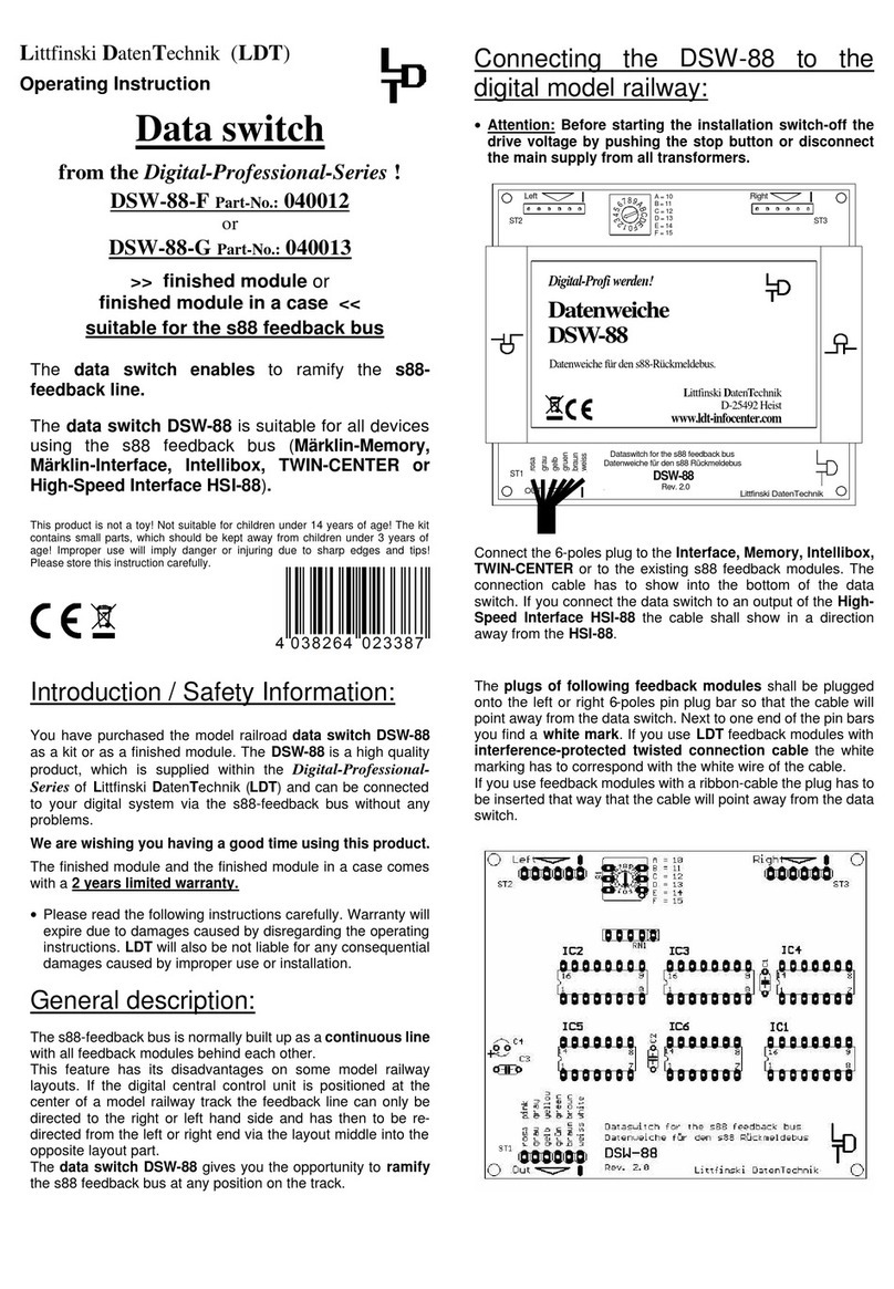
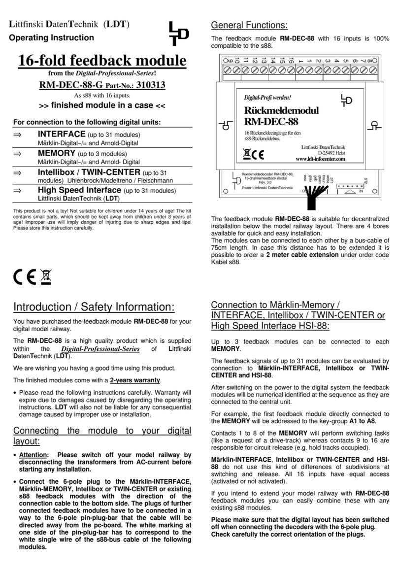
Connecting the s88-ClockMaster with the
switch
board light decoder GBS-DEC-s88 and eventually
with the
Service-Module:
•Attention: Before starting the installation switch off the
drive voltage bypushing the stop button or disconnect the
main supply to all transformers.
Each switch-board light decoder GBS-DEC-s88
will be
supplied together with a 2 Meter s88-Bus Cable.
Connect the one side of the bus cable onto the 6-poles pin bar of
the switch-board light decoder GBS-DEC-s88 marked with
“s88-Out”. Connect the other side of the cable to the 6-poles pin
bar of the s88-ClockMaster marked with “s88-Bus” in a way that
the direction of the cable shows away from the PC-board.
Additionally attend to the white marking at one end of the pin
bar. This mark has to correspond to the white single wire of
the respective cable.
For adjusting the quantity of feedback modules which the s88-
ClockMaster has to consider additionally the Service Module
GBS-Service is required.
Connect the 15-poles pin bar of the Service-Module GBS-
Service to the 15-poles socket bar of the s88-ClockMaster.
The inserted pin bar shall have no offset to the socket bar.
The s88-ClockMaster receives the voltage supply via the
2-poles clamp KL1.
If the switch-board light decoder GBS-DEC-s88
and the
s88-
ClockMaster receives the power supply from a common
transformer you have to attend to the correct polarity of the
supply voltage. Important is the identification “yellow” and
“brown” at the clamps. The sample connection on the rearside
of this instruction shows the correct wiring.
Getting started:
If the s88-ClockMaster receives power supply the green LED
will glow after a short time and indicates the mode ready-to-
operate. The bus-clock timing will be created. The bus-clock can
be switched-on or -off with the keys Stop and Go. The red LED
will glow if the bus-clock has been switched-off.
A total of 32 16-fold Feedback Modules can be controlled by
one s88-ClockMaster. The factory setting is on 6units.
As the processing- respectively response-time of the
feedback system depends on the quantity of Feedback
Modules is it important to make a correct setting of the actual
connected feedback modules. For this adjustment you have to
switch-off the s88-ClockMaster and connect the Service
Module GBS-Service.
Adjusting the quantity of Feedback-Modules:
After switching-on the s88-ClockMaster the display of the
Service-Module indicates s88-CM Vx.yy. If the display of the
service module shows no correct image after first switching into
operation please turn careful the Trim-Pot R1 with a small
screw driver a half turn left and right until you can read the
display information optimal.
On the Service-Module you can find 4 push buttons which are
indicated within the following instruction with >links< (>left<),
>rechts< (>right<), >oben< (>top<) and >unten< (>bottom<)
At first push the key >rechts< (>right<). By first operation the
display will indicate the text Anzahl (qty) RM:06. With the key
>oben< (>top<) or >unten< (>bottom<) you can now adjust the
number of feedback modules between 1and 32.
Now activate the key >links< (>left<) or >rechts< (>right<).
The s88-ClockMaster will leave the setting mode and after a
short period the display of the service module indicates s88-CM
Vx.yy.
Now is the s88-ClockMaster in operation mode.
For the further operation is the Service-Module not necessarily
required. Eventually you can detach it from the s88-ClockMaster
provided that the supplyvoltage has been switched-off andthe
display is blank.
KL1
s88-bus
gelb braun
14...18V~
Littfinski DatenTechnik (LDT)
BU1
ST1
S1
S2
LED1LED2
ST2
StopGo
Go Stop
booster
++
s88-ClockMaster
Rev 1.0
s88-CM
Erzeugt den s88-Takt für den Gleisbildstellpult-
Decoder GBS-DEC-s88.
s88-ClockMaster
s88-CM
Digital-Profi werden!
Littfinski DatenTechnik (LDT)
www.ldt-infocenter.com

Made in Europe by
Littfinski DatenTechnik (LDT)
Bühler electronic GmbH
Ulmenstraße 43
15370 Fredersdorf / Germany
Phone: +49 (0) 33439 / 867-0
Internet: www.ldt-infocenter.com
Subject to technical changes and errors. 06/2019 by LDT
s88-ClockMaster
Rev 1.0
s88-CM
Service Modul aufstecken
connect Service Module
GBS-Service
Rev. 1.0
Littfinski DatenTechnik (LDT)
S1
S2
S4
S3
R1
ST1
KL1
s88-bus
gelb braun
14...18V~
Littfinski DatenTechnik (LDT)
BU1
ST1
S1
S2
LED1LED2
ST2
StopGo
Go Stop
booster
++
s88-ClockMaster
Rev 1.0
s88-CM
Erzeugt den s88-Takt für den Gleisbildstellpult-
Decoder GBS-DEC-s88.
s88-ClockMaster
s88-CM
Digital-Profi werden!
Littfinski DatenTechnik (LDT)
www.ldt-infocenter.com
Vom Modellbahntrafo
From transformer
gelb
yellow
braun
brown
gelb
yellow braun
brown
32 . . . 1
weiss
white weiss
white
KL1
s88-bus
gelb braun
14...18V~
Littfinski DatenTechnik (LDT)
BU1
ST1
S1
S2
LED1LED2
ST2
StopGo
Go Stop
booster
++
s88-ClockMaster
Rev1.0
s88-CM
Erzeugt den s88-Takt für den Gleisbildstellpult-
Decoder GBS-DEC-s88.
s88-ClockMaster
s88-CM
Digital-Profi werden!
Littfinski DatenTechnik (LDT)
www.ldt-infocenter.com
weiss
white
IN
10
9
11
8
7
6
5
4
3
2
1
12
13
14
15
16
KL6KL5KL4KL3KL2KL1
Littfinski DatenTechnik(LDT)
ST2ST1
Rückmeldemodul RM-88-N
16 - channel feedback module
Rev. 1.0
BU1 BU2
s88-N
OUT IN
s88-N
OUT
1 Rückmeldeeingänge für den
s88-Rückmeldebus.
Rückmeldemodul
RM-88-N
s88-N
Digital-Profi werden!
Littfinski DatenTechnik (LDT)
www.ldt-infocenter.com
8116924173225
. .. . . . . .
weiss
white
weiss
white
GBS-Master
Rev. 1.2
BU1
BU2
K
br.
J
KL1
rt
Littfinski DatenTechnik (LDT)
ST2 ST1
OUTIN s88s88
Bestellbezeichnung / Order code:
Kabel s88 0.5m, Kabel s88 1m
oder / or Kabel s88 2m
Bestellbezeichnung / Order code:
Kabel s88 0.5m, Kabel s88 1m
oder / or Kabel s88 2m
OUT IN INOUT
OUTIN IN
white
weiss
white
weiss
KL4 KL3 KL2 KL1
KL7
BU1 ST1
4
5
6
7
8
26
27
28
29
30
31
32
25
9
10
11
12
13
14
15
16
18
19
20
21
22
23
24
17
1
2
3
GBS-Display/ Light-Display
Rev. 1.8
Littfinski DatenTechnik (LDT)
KL5
braun
gelb
10...18V~
12...24V=
KL6 BU2
39
38
37
36
35
34
33
40
BU3
OUT
IN
This manual suits for next models
2
Other LDT Control Unit manuals
Popular Control Unit manuals by other brands
Pentair
Pentair FLECK 9100 SXT user guide
NameLessRC
NameLessRC D400 VTX+DVR AIO user manual

Defi
Defi Defi-Link ADVANCE Control Unit SE Operation manual

Honeywell
Honeywell Gamewell FCI Velociti Series Installation and maintenance instructions

Trimteck
Trimteck OPTIMUX OpDx Product instruction manual
Dometic
Dometic Elite Control Series Installation and operating manual
