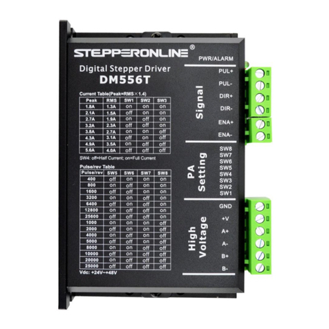
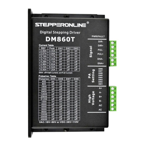
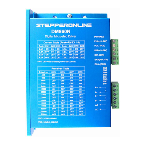
StepperOnline DM556N User manual

User’s Ma
nu
a
l
For
DM556N
Digital Microstep
Dr
i
ve
Version 1.1
Designed by STEPPERONLINE®
Manufactured by NC-THCH®
©2018 All Rights Reserved
#7 Zhongke Road, Jiangning, Nanjing, China
Tel: 086-25-8715-6578
Web site: www.omc-stepperonline.com
E-Mail: sales@stepperonline.com
Attention: Please read this manual carefully before using the drive!

Digital Microstep Driver DM556N
1
Table of Contents
1. Products Introductions.........................................................................................................2
1.1 Instructions & Features................................................................................................2
1.2 Features.....................................................................................................................2
1.3 Safety Instructions.......................................................................................................2
1.4 Applications................................................................................................................2
2. Specifications.......................................................................................................................3
2.1 Electrical Specifications...............................................................................................3
2.2 Operating Environment and other Specifications..........................................................3
2.3 Mechanical Specifications (Unit: mm) .......................................................................... 4
3. Driver Wirings Description....................................................................................................4
3.1 Control Signal Wirings Description................................................................................4
3.2 Motor Wirings Description............................................................................................5
3.3 Input Signals Description.............................................................................................5
3.4 Timing Diagram of Control Signals............................................................................... 6
3.5 Wiring Requirements...................................................................................................7
4. DIP Switch Setting...............................................................................................................7
4.1 Operating Current Setting............................................................................................7
4.2 Standstill Current Setting.............................................................................................8
4.3 Microstep Resolution Setting........................................................................................8
5. Power Supply Selection........................................................................................................8
5.1 Power Supply Precautions............................................................................................8
5.2 Power Supply Recommend...........................................................................................9
6. Motor selection....................................................................................................................9
6.1 Motor matching...........................................................................................................9
6.2 Motor connection........................................................................................................10
6.3 Input voltage and output current selection...................................................................10
7. Frequently Asked Questions.................................................................................................11

Digital Microstep Driver DM556N
2
1 Product Instructions
1.1 Instructions
The DM556N is a fully digital stepper driver developed with advanced DSP control algorithm based
on the latest motion control technology. It is especially effective in devices where users expect low
cost, low noise. Its motor auto-identification and parameter auto-configuration feature offers quick
setup to optimal modes with different motors.
1.2 Features
The driver of DM556N features as bellow:
Wide control signal voltage range, from +5V to 24V. Can be used directly without any
external circuit
Low noise, low motor speed
Average current control, two-phase sinusoidal current output
The servo microstep DSP algorithm, low noise, low vibration
The max. power supply voltage can be 40VAC/50VDC
Output peak current from 1.4A to 5.6A
The standstill current can be set to half
Can drive 4, 6 and 8 wire two-phase, four-phase stepper motors
High-speed optocoupler isolation signal input, pulse response frequency up to 200 kHz
Strong anti-high frequency interference ability
Easy to set output current
Microstep accuracy: 2, 4, 8, 16, 32, 64, 128, 5, 10, 20, 25, 40, 50, 100, 125
Overvoltage, undervoltage, overcurrent, and phase-to-phase short circuit protection
The max motor speed:500RPM(Recommend value: 200RPM).If you need higher motor
speed,recommend DM556T.
1.3 Safety Instructions
The product is powered by AC/DC power supply, please confirm that the power supply
voltage is within the allowable range.
Do not plug or unplug the cable when power on.
This product is not sealed, do not mix conductive foreign matter or flammable materials
inside. Pay attention to moisture-proof.
Keep the operating environment cool and ventilated when in use.
Connect to the stepper motor, adjust the current, work continuously for half an hour and
observe if the temperature is in the rated range. If the motor temperature is too high, please
contact the us.

Digital Microstep Driver DM556N
3
1.4 Applications
Suitable for a variety of medium-sized automation equipment and instruments, such as: engraving
machine, marking machine, cutting machine, laser phototypesetting, plotter, CNC machine tool, pick
and place device. It is especially effective in devices where users expect low cost, low noise.
2. Specifications
2.1 Electrical Specifications
Instruction
DM556N
Minimum
Typical
Maximum
Unit
Output
Current
1.4
-
5.6 (Peak)
Amps
Input Voltage
20
36
50 (contain the
ripple)
VDC
15
24
40(contain the
ripple)
VAC
Control
Signal Voltage
5
-
26(contain the
ripple)
VDC
Control
Signal
Current
7
10
16
mA
Signal Pulse
Frequency
0
-
200
KHZ
Insulation
Resistance
500
MΩ
2.2 Operating Environment and other Specifications
Cooling
Natural Cooling
Operating
Environment
Environment
Dustproof, anti-oil fog and
corrosive gases
Ambient Temperature
0℃– +50 ℃
Max. Operating
Temperature
70 ℃
Humidity
40-90% RH
(No condensation or water drop)
Vibration
10 – 55 Hz / 0.15 mm
Storage Temperature
-20℃– 125℃
Weight
Approx. 280g (9.88 oz)

Digital Microstep Driver DM556N
4
2.3 Mechanical Specifications (Unit: mm)
Figure 1: Mechanical specifications
Note: Side mounting is recommended for better heat dissipation
3. Driver Wirings Description
3.1 Control Signal Wirings Description
Pin Name
Descriptions
PUL(+5~24V)
Pulse control signal, falling edge is valid. For reliable response,
the pulse width should be greater than 2.5µs. PUL voltage range is
+5V~+24V.
PUL-(PUL)
DIR(+5~24V)
This signal can modify the motor direction. In order to ensure the
reliability of the motor, the DIR signal should be established at
least 5µs ahead of the PUL signal. The initial running direction of
the motor is related to the wiring sequence of the motor. DIR
voltage range is +5V~+24V.
DIR-(DIR)
ENA(+5~24V)
The ENA signal is used to enable/disable. When ENA is OFF, the
driver is enabled; When ON, the driver is disable. Usually, the
wirings are idle and the motor is enabled. ENA voltage range is
+5V~+24V.
ENA-(ENA)

Digital Microstep Driver DM556N
5
3.2 Motor Wirings Description
Pin Name
Descriptions
AC
Power input, AC and DC universal. VAC: 15~40 V; VDC: 20~50 V
AC
A+
Motor phase A wirings. Interchange A+, A-, can change the running
direction of the motor once
A-
B+
Motor phase B wirings. Interchange B+, B-, can change the running
direction of the motor once
B-
3.3 Input Signals Description
DM556N has high-speed optocoupler inside that allows reception of long-line controller signal, open
collector signal, and PNP-type output signal. In the harsh environment, we recommend using a
long-line controller circuit to make the anti-interference ability strong. Taking the open collector and
PNP-type output as an example, and the connection circuit is as follows:
Figure 2: Connection to open-collector signal (common-anode)

Digital Microstep Driver DM556N
6
Figure 3: Connection to PNP-type signal(common-cathode)
3.4 Timing Diagram of Control Signals
In order to avoid some malfunctions and deviations, PUL, DIR and ENA signals should observe
some rules, as following figure show.
Figure 4: Timing diagram of control signals
Remark:
(1). t1: ENA signal must be ahead of DIR signal by at least 5µs. Usually, ENA+ and ENA- should
be suspended.
(2). t2: DIR signal must be ahead of PUL signal falling edge by 5µs to ensure correct direction.
(3). t3: Pulse width is not less than 2.5µs.

Digital Microstep Driver DM556N
7
(4). t4: Low level width is not less than 2.5µs.
3.5 Wiring Requirements
(1). In order to prevent the driver from being disturbed, it is recommended to use a twisted-pair
shielded cable and the shield layer grounded (single-ended ground). Make sure the connection is
true ground, otherwise the interference may be more serious.
(2). The control signal lines and the motor lines are not allowed to be side by side, preferably
separated by at least 10 cm. Otherwise, the motor electromagnetic noise easily interfere with the
control signal, causing the motor to be inaccurately positioned and the system is unstable.
(3). If one power supply is used for multiple drivers, parallel mode should be used at the power
supply, and it is not allowed to connect to another driver at the driver’s pin.
(4). It is strictly forbidden to plug and unplug the driver motor line terminal. When the energized
motor stops, there is still a large current flowing through the coil. Pulling out the motor line
terminal will cause a huge instantaneous induced electromotive force to burn the driver.
(5). It is strictly forbidden to add tin to the wire lead and then connect the terminal. Otherwise, the
terminal may be damaged due to the contact resistance becoming large and overheating.
4. DIP Switch Setting
The DM556N driver uses a 8-bit DIP switch to set operating current, standstill current, and
microstep resolution. The detailed description is as follows:
SW1
SW2
SW3
SW4
SW5
SW6
SW7
SW8
Figure 5: DIP switch setting
4.1 Operating Current Setting
The first three bits (SW1, SW2, SW3) of the DIP switches are used to set the operating current of the
motor. Select the setting that is closest value to the motor as required current.
Peak Current
RMS Current
SW1
SW2
SW3
1.4A
1.0A
ON
ON
ON
2.1A
1.5A
OFF
ON
ON
2.7A
1.9A
ON
OFF
ON
3.2A
2.3A
OFF
OFF
ON
3.8A
2.7A
ON
ON
OFF
4.3A
3.0A
OFF
ON
OFF
4.9A
3.5A
ON
OFF
OFF
5.6A
4.0A
OFF
OFF
OFF
Operating current
Standstill current
Microstep resolution

Digital Microstep Driver DM556N
8
4.2 Standstill Current Setting
The standstill current can be set with the SW4, OFF means the standstill current is set to about half
of the dynamic current (60%), and ON means the standstill current is the same as the operating
current. In general, SW4 should be set to OFF, so that the heat generated by the motor and the driver
is reduced, and the reliability is improved. After the pulse train stops for about 0.2 seconds, the
current is automatically reduced to 60% of the set value, and the heat output is theoretically reduced
to 36% (heat generation is proportional to the square of the current). When set to OFF, the motor's
start response will be faster.
4.3 Microstep Resolution Setting
Microstep resolution is set by SW5-SW8 of the DIP switches as shown in the following table (the
table is use for 1.8° motor):
Microstep
Pulses/rev.
SW5
SW6
SW7
SW8
2
400
OFF
ON
ON
ON
4
800
ON
OFF
ON
ON
8
1600
OFF
OFF
ON
ON
16
3200
ON
ON
OFF
ON
32
6400
OFF
ON
OFF
ON
64
12800
ON
OFF
OFF
ON
128
25600
OFF
OFF
OFF
ON
5
1000
ON
ON
ON
OFF
10
2000
OFF
ON
ON
OFF
20
4000
ON
OFF
ON
OFF
25
5000
OFF
OFF
ON
OFF
40
8000
ON
ON
OFF
OFF
50
10000
OFF
ON
OFF
OFF
100
20000
ON
OFF
OFF
OFF
125
25000
OFF
OFF
OFF
OFF
5. Power Supply Selection
The driver can work normally between DC20V-50V / AC15V-40V. Please note that the peak ripple
of the power supply should not exceed this value. If using a transformer to supply power, you should
consider the fluctuation rate of the local power grid to select the appropriate transformer power
supply. If using a DC power supply, be aware that the output current range of the power supply
needs to be greater than the operating current of the motor.
5.1 Power Supply Precautions
(1). It is best to use an unregulated power supply.
(2). When using an unregulated power supply, the output power of the power supply needs to be
greater than to 60% of the driver set current.

Digital Microstep Driver DM556N
9
(3). When using a regulated DC power supply, the output current of the power supply should be
greater than or equal to the operating current of the driver.
(4). In order to reduce costs, two or three drivers can share a power supply, but should ensure that
the power of the power supply is large enough.
5.2 Power Supply Recommend
(1). For DC power, it is recommended to use unregulated DC power supply
24VDC/36VDC/48VDC.
(2). For AC power, it is recommended to use transformer power 24VAC/36VAC.
6. Motor selection
It can be used to drive two-phase, four-phase hybrid stepper motors with an step angle of 1.8 degrees
and 0.9 degrees.
When selecting a motor, the torque and rated current of the motor are mainly considered parameters.
The torque is mainly determined by the size of the motor. The large-sized motor has a large torque;
the current is mainly related to the inductance, and the small-inductance motor has a high-speed
performance, but the current is large. The DM556N can drive Nema 23, Nema 24 two-phase and
four-phase hybrid stepper motors.
6.1 Motor matching
(1). Define the load torque, the ratio of the working speed range
]2/1/)a[ 2rotation
2
1aJDMiJCT
(
load theof inertia ofMoment :J
load theofon acceleratiangular Maximum
1
:a
onacceleratiangular screwor on wheelTransmissi
2:a
weightLoad:M
1.4-1.2 valuedrecommende factor,Safety :C
friction oft Coefficien:
efficiencyRotation :
diameter disc and Screw:D
inertia ofmoment screwor wheelRotating
rotation:J
ratioRotation :I
(2). Factors that determine the motor output torque:
For a given stepper motor and solution, the output torque has the following characteristics:
a. The larger the operating current of the motor, the greater the output torque, but the more copper
loss of the motor, the more heat the motor generates;
b. The higher the supply voltage of the driver, the higher the high speed torque of the motor;
c. According to the torque curve of the stepper motor, the high speed is smaller than the medium
and low speed torque.

Digital Microstep Driver DM556N
10
Figure 6: Torque frequency curve diagram
6.2 Motor connection
Figure 7: Motor connection diagram
6.3 Input voltage and output current selection
The DM556N driver can drive all two-phase and four-phase hybrid stepper motors. In order to
obtain the best driving effect, it is necessary to select a reasonable supply voltage and set current.
The voltage of the power determines the high-speed performance of the motor, and the current
determines the torque of the motor.
(1). Supply voltage setting
In general, the higher the supply voltage, the greater the torque at high-speeds, and the greater the
loss of speed at high speeds. On the other hand, if the voltage is too high, the motor will generate
more heat and may even damage the driver. At high voltages, the vibration of the motor at low
speeds will be greater.
(2). Output current setting
For the same motor, the larger the current setting value, the larger the motor output torque, but the
heat generated by the motor and the driver is more serious when the current is large. The calorific
value is not only related to the current setting value, but also to the motor motion form and the
motor dwell time. The following setting method uses the rated current value of the stepper motor
as a reference, but the optimum value in practical applications should be adjusted based on this
value. If the temperature is very low (<40℃), the current setting value can be increased to increase
the motor output power (torque and high-speed performance).
a. 4-wire motor and high-speed mode of 6-wire motor: output current is set equal to or slightly less
than the rated current of the motor;
b. High torque mode of 6-wire motor: output current is set to 70% of rated current;
c. Series connection of 8-wire motor: because the resistance increases in series, the output current
should be set to 70% of the rated current of the motor;

Digital Microstep Driver DM556N
11
d. The parallel connection of 8-wire motor: the output current can be set to 1.4 times the rated
current of the motor.
Note: Please run the motor for 30-60 minutes after the current is set. If the motor temperature rises
too high (>70°C), the current setting should be reduced. Therefore, the general situation is to set the
current to a value that the motor’s temperature is warm but not too hot when the motor is working
for a long time.
7. Frequently Asked Questions
(1). Q: When using the stepper drive for the first time, how can I get started as soon as possible?
A: After the power supply and motor are properly connected, only the pulse signal is connected
(set the frequency to 1KHZ first), the microstep is set to 16, the DIR and ENA are suspended. At
this time, the motor defaults to forward after power-on. After running correctly, test the functions
of acceleration (increasing frequency), direction, microstep and ENA.
(2). Q: If the control signal voltage is higher than 5V, must I add a series resistor?
A: It is not required. This driver has been compatible with all signal voltages between 5V and 24V.
(3). Q: After the driver is working for a long time, the outer casing is hot, is it normal?
A: This is normal. Under normal temperature, the outer casing will not affect the performance
below 70°C.
(4). Q: After the wiring, the power indicator light is on, but the motor does not turn. What is the
reason?
A: If the wiring is correct (the enable signal is not connected), but still does not turn, it indicates
that the controller drive capability is not enough, please ensure that the controller has 5mA drive
capability, or check if the driver signal is a double pulse format?
(5). Q: How to judge the definition of four lines of stepper motor?
A: Connect any two wires of the motor together, at this time, there is resistance to twist the motor
shaft by hand. The two wires are in the same phase and can be connected to the driver A+ and A-.
If the other two wires are connected together, there will still be resistance. These two wires are
connected to B+ B-. Or use a multimeter to measure, the two wires that pass through each other
are the same phase, which can be connected to A+, A- or B+, B-.
Thank you for your support of STEEPERONLINE!
Table of contents
Other StepperOnline DC Drive manuals
StepperOnline
StepperOnline RS485 User manual

StepperOnline
StepperOnline BLD-530S User manual

StepperOnline
StepperOnline DM860I User manual

StepperOnline
StepperOnline DM556T User manual

StepperOnline
StepperOnline BLD-510S User manual

StepperOnline
StepperOnline DMT556T User manual

StepperOnline
StepperOnline Y Series User manual
StepperOnline
StepperOnline DM860T User manual

StepperOnline
StepperOnline DM556T User manual
StepperOnline
StepperOnline BLD-550S User manual