Eurotron MicroCal T100+ User manual
MicroCal T100+
MicroCal T500+
MicroCal T1100+
Portable Temperature Calibrators
Instruction Manual MM850518 Ed.01
_________________________________________________________ _________________________________________________________
Instruction Manual MM850518 ed.01
______________________________________________2_______________________________________________
INTRODUCTORY NOTE
This manual has been with all the information you need to install, operate and maintain the dry block temperature
calibrator MicroCal T100+/T500+/T1100+ and its accessories.
Eurotron has used the best care and efforts in preparing this book and believes the information in this publication are
accurate. The Eurotron products are subjected to continuous improvement, in order to pursue the technological
leadership; these improvements could require changes to the information of this book.
Eurotron reserves the right to change such information without notice.
No part of this document may be stored in a retrieval system, or transmitted in any form, electronic or mechanical,
without prior written permission of Eurotron Instruments SpA.
MicroCal T series calibrators use sophisticated analogic and digital technologies. Any maintenance operation must be
carried out by qualified personnel ONLY. Eurotron supplies instructions and operative procedures for any operation on
the instrument. We recommend to contact our technicians for any support requirements.
MicroCal T is fully tested in conformity with the directive n°89/336/CEE Electromagnetic Compatibility. Eurotron shall
not be liable in any event, technical and publishing error or omissions, for any incidental and consequential damages, in
connection with, or arising out of the use of this book.
All right reserved
Copyright © 1998, 2004
EUROPEAN Headquarters
Eurotron Instruments SpA
Viale F.lli Casiraghi 409/413
20099 Sesto S. Giovanni (MI)
Tel. : +39-02 24 88 201
FAX: +39-02 24 40 286
USA Headquarters
E-Instruments Group LLC
172 Middletown Blvd – Suite B201
Langhorne, PA 19047
Tel.: 215 750 1212
FAX: 215 750 1399
WARNING
Hazardous voltage are present in this electrical equipment during operation.
Non-observance of the safety instruction can result in severe personal injury or property damage.
Only qualified personnel should work on or around this equipment after becoming familiar with
all warnings, safety notices, and maintenance procedures contained herein.
Only qualified personnel or our personnel should work on this equipment for maintenance
operation.
The successful and safe operation of this equipment is dependant on proper handing, operation
and maintenance.

_________________________________________________________ _________________________________________________________
Instruction Manual MM850518 ed.01
______________________________________________3_______________________________________________
CONTENTS
1SPECIFICATIONS.......................................................................................................5
1.1 MicroCal T100+ .................................................................................................................................... 5
1.2 MicroCal T500+ .................................................................................................................................... 6
1.3 MicroCal T1100+ .................................................................................................................................. 8
2ORDERING CODE ......................................................................................................9
2.1 MicroCal T100+ .................................................................................................................................... 9
2.2 MicroCal T500+ .................................................................................................................................... 9
2.3 MicroCal T1100+ .................................................................................................................................. 9
3RECOMMANDATIONS .............................................................................................11
3.1 Position of the probe:.......................................................................................................................... 11
4SAFETY INSTRUCTIONS.........................................................................................13
5PREPARATION.........................................................................................................14
5.1 Installation........................................................................................................................................... 14
5.1.1 Removal of packaging..................................................................................................................... 14
5.1.2 Positioning the calibrator ................................................................................................................. 14
5.1.3 Supply.............................................................................................................................................. 14
5.1.4 How to fit the equalising block in MicroCal T1100+ ........................................................................ 14
6OPERATION PROCEDURE......................................................................................16
6.1 Operation description ......................................................................................................................... 16
6.2 Description of instrument.................................................................................................................... 16
6.2.1 Thermoregulator.............................................................................................................................. 16
6.2.2 Main switch...................................................................................................................................... 16
6.2.3 Overheating warning light................................................................................................................ 16
6.2.4 Ventilation holes .............................................................................................................................. 16
6.2.5 Heating resistance........................................................................................................................... 16
6.2.6 Equalising block .............................................................................................................................. 16
6.2.7 Temperature sensors ...................................................................................................................... 17
6.3 Start-up instructions............................................................................................................................ 17
6.4 Use of the function.............................................................................................................................. 19
6.4.1 Reading the external probes ........................................................................................................... 19
6.4.2 Switch test (SW. ON SW. OFF) ..................................................................................................... 19
6.4.3 Serial communication ...................................................................................................................... 19
6.5 Re-calibration methods....................................................................................................................... 19
7TYPICAL FAULTS ....................................................................................................21
8REGULATOR ............................................................................................................22
8.1 REGULATOR’S FUNCTIONS ................................................................................22
9MICRO-PROCESSOR REGULATOR .......................................................................26
10 WARRANTY..............................................................................................................27
10.1 Warranty terms................................................................................................................................ 27

_________________________________________________________ _________________________________________________________
Instruction Manual MM850518 ed.01
______________________________________________4_______________________________________________
10.2 Letter of conformity.......................................................................................................................... 27
APPENDIX ........................................................................................................................28
A1 EMC Conformity ................................................................................................................................. 29

_________________________________________________________ _________________________________________________________
Instruction Manual MM850518 ed.01
______________________________________________5_______________________________________________
1 SPECIFICATIONS
1.1 MicroCal T100+
Environmental range: temperature +10÷+35°C, R.H. max. 90%.
(Standard models with ø26mm hole)
•Operative range : -28 ÷ +150°C (ambient temperature = 18°C)
•Stability : ±0.03°C **
•Resolution : 0,01/0,1°C
•Reading accuracy : ±0,15°C **
•Regulation & reading probe : Pt 100 class A din43760
•Auxiliary inputs : Pt100 and Tc J, K, N, R, S(only for Model 2I)
•Reading : °C or °F
•Serial communication : RS 232
•Increase gradient : 20°C/1’ **
•Decrease gradient : 25°C/1’ **
•Standard block : ø26 x 135mm - Ø35 x 135mm
•Temperature ramps : min. 0,1°C/1’
•Thermostat test : 12 Vcc.
•Voltage : 230V 50Hz (100/115V by required) 50/60Hz.
•Power : 300VA.
•Electric protection : 2,5A T. fuse (3A F for 100-115V)
•Calibrator measurements : 160x370 x h. 330 mm
•Measurements of case : 520x330 x h. 500 mm
•Weight : 10 Kg only calibrator; 17Kg with travelling-case.
•Structure in flanged plate with rotating handle.
•Thermostatic well in aluminium with a holes ø26mm or 36mm, 135mm dept. Reducer inserts: ø25,7x135mm or
ø35,7x130mm.
•Regulation of the temperature with PID µcontroller.
•Switch test.
•Internal cryostat with Peltier elements.
•Electronic control components thermally insulated with forced air sistem.
•Removable upper protection grid.
•Total absence of environmentally harmful cooling liquids.
•Socket with main cable and protection fuses.
•Display back light control.
•Electromagnetic compatibility : Emission EN50081-1 / Immunity EN50082-2
NOTE: The data marked with ** has been recorded at an ambient temperature of 20°C±3, power supply
230V±10%, with Pt100 ø6 inserted in the block. The above-mentioned data keep valid for one year
after the issuing of the calibrating certificate; afterwards it is necessary to carry out the oven re-
calibration.

_________________________________________________________ _________________________________________________________
Instruction Manual MM850518 ed.01
______________________________________________6_______________________________________________
1.2 MicroCal T500+
Environmental range: temperature +10 ÷ +35°C, R.H. max. 90%.
Standard model with aluminium block measuring 50mm diameter
•Operative range: Environment ÷ +550°C**
•Stability: ±0.05°C a 450°C **
•Display resolution: 0,01/0,1°C
•Reading accuracy: ±0,3°C a 450°C
•Regulation & reading probe: Pt 100 class A din43760
•Auxiliary input : Pt100 and Tc J, K, N, R, S(only for Model 2I)
•Reading: °C or °F
•Interface: RS 232
•Maximum ascent rate: 20°C/1’ **
•Maximum descent rate: 20÷25°C/1’ ** (depending on the starting temperature)
•Test wells: 4 holes ø4,5-6,5-9,5-17 x 185mm
•Temperature ramps: minimum 0,1°C/1’
•Thermostat test: 12 Vcc.
•Power supply: 230V 50/60Hz (110/115V by request)
•Power: 800VA.
•Size : 140x370 x 330 mm
•Case size : 330x520 x H. 500 mm
•Weight of calibrator : 10 Kg (17Kg including carrying case and accessories).
)Model with aluminium-bronze block measuring 50mm diameter
•Operative range : Environment ÷ +600°C**
•Stability : ±0.1°C a 450°C **
•Maximum ascent rate : 20÷22°C/1’ **
•Maximum descent rate : 8÷12°C/1’ ** (∆t = 300°C).
•Weight of calibrator : 17Kg
•Test wells with perforation standard or by request
)Model with aluminium block measuring 65mm diameter:
•Operative range : Environment ÷ +550°C**
•Stability : ±0.1°C a 450°C **
•Maximum ascent rate : 15÷20°C/1’ **
•Maximum descent rate : 3÷5°C/1’ ** (∆t = 300°C).
•Weight of calibrator : 10Kg
•Test wells with perforation by request
)Model with aluminium-bronze block measuring 65mm diameter:
•Operative range : Environment ÷ +600°C**
•Stability: ±0.1°C a 450°C **
•Maximum ascent rate : 15÷20°C/1’ **
•Maximum descent rate : 3÷5°C/1’ ** (∆t = 300°C).
•Weight of calibrator : 17Kg
•Test wells with perforation by request
•Structure in flanged plate with rotating handle.
•Micro-processor operated temperature regulator.
•Automatic resetting safety thermostat.
•Switch test.
•Internal oven in stainless steel.
•Electronic control components thermally insulated.
•Forced air cooling system.
•Removable upper protection grid.
•Total absence of environmentally harmful cooling liquids.
•Socket with main cable and protection fuses.
•Display back light control.
•Electromagnetic compatibility : Emission EN50081-2 / Immunity EN50082-2
NOTE: The data marked with ** has been recorded at an ambient temperature of 20°C±3, power supply
230V±10%, with Pt100 ø4.5mm inserted in the block.
The above-mentioned data keep valid for one year after the issuing of the calibrating certificate;

_________________________________________________________ _________________________________________________________
Instruction Manual MM850518 ed.01
______________________________________________7_______________________________________________
afterwards it is necessary to carry out the oven re-calibration.

_________________________________________________________ _________________________________________________________
Instruction Manual MM850518 ed.01
______________________________________________8_______________________________________________
1.3 MicroCal T1100+
•Environmental range: temperature +10÷+35°C, R.H. max. 90%.
•Operative range: 200÷+1100°C **.
•Stability: ±0.3°C**.
•Maximum ascent rate: 18°C/min.**(from 20 to 1000°C)
•Maximum descent rate: 6°C/min.**( from 1000 to 600°C) - 3.8°C/min**( from 700 to 400°C)
•Stability time: 20 min.
•Display resolution: 1/0,1°C
•Radial uniformity: ±0.4°C
•Axial uniformity: ±0.4°C (on 100mm)
•Reading precision: ±0.3% ±1 digit V.F.S.
•Interface: RS 232
•Power supply: 230V 50/60Hz (115/100V by request) 850 VA
•Dimension of internal oven: ø45x200mm
•Size: 170x330xh.450 mm
•Weight: 12 Kg
•Structure in flanged plate with handle.
•Micro-processor operated temperature regulator.
•Manual resetting safety thermostat.
•The internal oven consist of a quartz tube hearted by a ceramic resistance, all mounted in an aluminium structure.
•Standard insert Inconel made, ø44mmx175mm dept, fitted with 4 holes 7-9-11-13.5mm in diameter, 155 mm deep.
Possibility of special drilling.
•Thermocouple for regulation and reading; thermocouple connected at the thermostat.
•Forced air cooling system.
•Upper protection grid.
•Socket with main cable and protection fuses.
•Electromagnetic compatibility : Emission EN50081-1 / Immunity EN50082-2
NOTE: The data marked with ** has been recorded at an ambient temperature of 20°C±3, power supply
230V±10%, thermocouples inserted in the block.
The above-mentioned data keep valid for one year after the issuing of the calibrating certificate;
afterwards it is necessary to carry out the oven re-calibration.
MICRO-PROCESSOR DATA
•Display: 2 lines 20ch x line (3.2x5.5) back lighting.
•Resolution: 0.01°C/0.1°C.
•processor: 80C552
•A/D converter: Σ-∆24 bits
•E2PROM memory for recording parameters.
•RS232 Single serial output.

_________________________________________________________ _________________________________________________________
Instruction Manual MM850518 ed.01
______________________________________________9_______________________________________________
2 ORDERING CODE
2.1 MicroCal T100+
Cat. 8172 - A - B - C
Table A Options
0 None
1 Aluminium carrying case (EE880063)
3 Two channels TCs & Pt100 auxiliary input
4 Vinyl carrying case (BB880047)
9 Special drilling insert
Table B Power Supply
1 120 Vac with USA plug
2 230 Vac Schuko plug
3 240 Vac UK plug
4 230 Vac European plug
5 100 Vac with Japan/USA plug
Table C Calibration Certificate
1 Eurotron certificate
2.2 MicroCal T500+
Cat. 8174 - A - B - C
Table A Options
0 None
1 Aluminium carrying case (EE880063)
2 Extended temperature range to 600°C (MicroCal T500 only)
3 Two channels TCs & Pt100 auxiliary input
4 Vinyl carrying case (BB880047)
9 Special drilling insert
Table B Power Supply
1 120 Vac with USA plug
2 230 Vac Schuko plug
3 240 Vac UK plug
4 230 Vac European plug
5 100 Vac with Japan/USA plug
Table C Calibration Certificate
1 Eurotron certificate
2.3 MicroCal T1100+
Cat. 8176 - A - B - C
Table A Options
0 None
1 Aluminium carrying case (EE880064)
3 Two channels TCs & Pt100 auxiliary input
4 Vinyl carrying case (BB880047)
9 Special drilling insert
Table B Power Supply
1 120 Vac with USA plug

_________________________________________________________ _________________________________________________________
Instruction Manual MM850518 ed.01
______________________________________________10_______________________________________________
2 230 Vac Schuko plug
3 240 Vac UK plug
4 230 Vac European plug
5 100 Vac with Japan/USA plug
Table C Calibration Certificate
1 Eurotron certificate
Note : Custom insert blocks are available on request

_________________________________________________________ _________________________________________________________
Instruction Manual MM850518 ed.01
______________________________________________11_______________________________________________
3 RECOMMANDATIONS
ATTENTION
THE µPROCESSOR REGULATOR HAS BEEN CONFIGURED IN FACTORY WITH THE PARAMETERS SUITED TO WORK IN THE RESPECT OF
THE TECHNICAL SPECIFICATIONS.DON’T CHANGE THESE PARAMETERS TO AVOID MALFUNCTION OR BREAKING OF THE CALIBRATOR
WITH RISKS OF SERIOUS PERSONAL INJURY.
ATTENTION
REMEMBER TO SET UP AMBIENT TEMPERATURE AND LEAVE COOLING DOWN BEFORE SWITCHING OFF THE
CALIBRATOR
3.1 Position of the probe:
N.B: For the positioning of the insert inside the oven, follow the instruction on paragraph 5
To obtain the best result, follow the advises:
•Measure the diameter of the probe being checked.
•MicroCal T1100+: Check that the diameter of the hole in the calibration block is at least 1mm bigger than the diameter
of the probe. If this is not the case, use the block with the above-mentioned tolerances (fig.1).
•MicroCal T100+: Use the reduction insert; check that the diameter of the hole is at least 0.3mm bigger than the
diameter of the probe.
•MicroCal T500+: Check that the diameter of the hole in the calibration block is
1. at least 0.5mm bigger than the diameter of the probe for diameter of the probe up to 8mm,
2. at least 0.7mm bigger than the diameter of the probe for diameter of the probe up to 12mm,
3. at least 0.5mm bigger than the diameter of the probe for diameter of the probe up to 8mm . If this is not the
case If this is not the case use the reduction wells with the above-mentioned tolerances.
•Avoid using holes which are too accurate and do not force the probes into the block.
•Insert the probe up to the bottom of the block: the sensitive element is in the optimal calibration zone (fig. 2).
•When calibrating using probes shorter than the length of the hole in the block, position the sample reference sensor at
the same height as the sensor which is to be checked
•Calibration with a reference: take care to position the two probes, the standard one and the calibration one, at the same
dept and as close together as possible (fig. 3).
•Always verify the range of the probes to be calibrated before using; the maximum temperature of the probes should be
higher then the temperature of the liquid otherwise the probe could break.
Advice:
•The temperature difference is proportional to the difference between the diameter of the probe and the diameter
of the hole.
•Do not insert the probe when the instrument has already reached the set temperature; thermal shock causes

_________________________________________________________ _________________________________________________________
Instruction Manual MM850518 ed.01
______________________________________________12_______________________________________________
instability and breakage of the sensitive element.
•For the calibration of temperature transducer with special execution, call our technical office and ask for equaliser
block with special drillings.

_________________________________________________________ _________________________________________________________
Instruction Manual MM850518 ed.01
______________________________________________13_______________________________________________
4 SAFETY INSTRUCTIONS
ATTENTION:
•Due to the fact that the thermostat is a portable instrument to be used in the field, it is very important to ensure that
the socket has been earthen correctly when connecting it to the electricity supply.
•Carry out the maintenance and repair operation only with the equipment at ambient temperature and disconnected
from the electric power.
•Don’t touch the probe to calibrate when it’s in the block.
•After using wait for the stabilisation at ambient temperature before switch off the calibrator.
•Don’t switch off the calibrator when it work at high temperature because the protection grid and the carpentry may
overheat.
•Don’t put anything near the fan-exit (4) because of the hot air when oven is on.
•When the calibrator must to be moved, remove the block from the quartz tube in order to prevent breakage of the
tube.
•It is a good idea if these operations are carried out with the calibrator as close to ambient
•temperature as possible.
•Never put any type of liquid inside the block.
•Don’t change absolutely the configuration parameters.
•Don’t put anything on the top of the calibrator.
•Never put any type of liquid inside the calibration block.
•...... use common sense any time.
The equipment adopt the following devices to protect operation from hazard:
•When there is a breakage in the temperature sensor (8) this is recognised by the thermoregulator which switches off
the heat output.
•If the temperature exceeds 1110°C the thermoregulator switches on a safety device which switches off the static
heating relay
•Max. temperature safety thermostat (10), with a K thermocouple, to disconnect the heating resistance each time the
temperature exceeds 1500°C.
•Protection grid to avoid any contact with the internal oven.
•Protection fuses (3)
•Ground conductor.
ADVICE FOR MICROCAL T100+
AFTER EVERY USE AT LOW TEMPERATURE REMEMBER TO SET UP 60°-70°C FOR ONE HOUR IN ORDER TO
EVAPORATE THE WATER IN THE WELL THEN SET AMBIENT TEMPERATURE AND LEAVE FOR SAME MINUTES
BEFORE SWITCHING OFF

_________________________________________________________ _________________________________________________________
Instruction Manual MM850518 ed.01
______________________________________________14_______________________________________________
5 PREPARATION
1. Remove the calibrator from the packaging (5.1.1) and place it on a flat surface (5.1.2).
2. Make sure that the instrument has been correctly earthen.
3. Supply the oven with line 230V, 50Hz + earth (5.1.3).
4. Insert the equalising block into the furnace: reference at the instruction on paragraph 5.1.4
5. Before start the calibration read with attention the instruction manual, specially the paragraph 3: - General
recommendation.
5.1 Installation
5.1.1 Removal of packaging
The calibrator is equipped with packaging suitable for transport and traditional shipping systems. Any damage caused
during transport must be notified immediately to the carrier and a claim must be made.
The equalising block is packed separately to avoid breaking the quartz tube during transport. The block must be fitted
into the calibrator when it is ready to be used.
5.1.2 Positioning the calibrator
Position the calibrator in a safe clean place; leave enough space around the calibrator to allow the air to circulate well.
DANGER:
THE CALIBRATOR IS SUITABLE FOR OPERATING AT HIGH TEMPERATURES WITH THE CONSEQUENT DANGER OF FIRE.KEEP IT AWAY
FROM ANY TYPE OF INFLAMMABLE MATERIALS AND,NEVER PUT ANY TYPE OF LIQUID INSIDE THE BLOCK (REFERENCE TO PARAGRAPH
4)
5.1.3 Supply
The calibrator runs on a voltage of 230 Vac (110-100V by request), 50/60Hz.
A 2.5mt. cable is supplied with the calibrator fitted with 2 conductors plus earth.
Make sure that the plant is earthen correctly before switching the instrument on.
5.1.4 How to fit the equalising block in MicroCal T1100+
After the furnace generally been installed, the equaliser block and the ceramic fibber insulation may be inserted.
Carefully insert the block and the upper insulation into the tube (see annexed drawing). Care must be taken to prevent
dirt, insulation, or other foreign materials from getting between the block and the quartz tube or it might break during
heat up due to thermal expansion differences. The fit between the block and the tube is typically loose in order to
accommodate this expansion.
A handle is provided to insert the block. It consist of a stainless steel rod with a M8x15 threaded end which is screwed
into the top of the block. The block is then lowered down over the control and cut-out sensor using the handle allowed to
rest on the ceramic fibber insulation on the bottom of the well. There are grooves on either side of the block for the
sensor to slide into. The grooves have a tapered opening at the bottom to facilitate entry of the sensor.
Insert the ceramic fibber insulation on the top of the block, using the block extractor.
Centre the holes of the upper insulation with the holes of the equalisation block.
WARNING:
TO AVOID ANY SMELL IN THE ROOM IT IS BETTER TO SWITCH ON THE CALIBRATOR OUTSIDE THE ROOM FOR THE FIRST TIME.
WHENEVER THE CALIBRATOR HAS TO BE MOVED,REMOVE THE BLOCK FROM THE QUARTZ TUBE IN ORDER TO PREVENT BREAKAGE OF
THE TUBE.
IT IS A GOOD IDEA IF THESE OPERATIONS ARE CARRIED OUT WITH THE CALIBRATOR AS CLOSE TO AMBIENT TEMPERATURE AS
POSSIBLE.

_________________________________________________________ _________________________________________________________
Instruction Manual MM850518 ed.01
______________________________________________15_______________________________________________
COMMAND LIST
POS. DESCRIPTION
1 SUPPLY SOCKET
2 MAIN SWITCH
3 PROTECTION FUSES
4 SWITCH TEST BUSHES
5 RS-232 SOCKET
6 MAX TEMPERATURE LAMP
7 LED: HEATING – COOLING – SWITCH TEST
8 DISPLAY
13 EXTERNAL PROBES SOCKETS
14 EQUALISER BLOCK
16 PROTECTION GRID
17 BLOCK EXTRACTOR

_________________________________________________________ _________________________________________________________
Instruction Manual MM850518 ed.01
______________________________________________16_______________________________________________
6 OPERATION PROCEDURE
6.1 Operation description
The MicroCal T calibrator consist of an equaliser block fitted with holes into which the sensors to be calibrated are
inserted.
A heater element heats the block and an electronic µcontroller with static relay output checks and regulates the
temperature.
A fan is fitted inside the regulating container, which prevents the metal structure from heating.
6.2 Description of instrument
6.2.1 Thermoregulator
The thermoregulator (8) is a PID microprocessor, which can be set inside the calibrator temperature range.
•DISPLAY UPPER LINE: indication of the temperature measured inside the block.
•DISPLAY LOWER LINE: indication of adjustment set-point; indication of external probes if selected; setting
parameters .
•DT KEY: used to increment (decrement) any numerical parameter. The increment (decrement) speed is proportional
to the time the key remains depressed.
•F KEY: allow access to the various parameters (repeatedly press), access to the various phases of configuration
(press F + 5).
•E KEY: allow confirming the set parameter.
The thermoregulator is endowed with eight bushes (13) that can be set as Pt100 or Tc.
6.2.2 Main switch
The main switch (2) is found on the rear of the instrument; it is fitted with a socket for the voltage cable, a main switch and
two fuses of 5A for 230V mod. & 8A for 115V models.
Note: use only fast fuses F. 6,3x32mm to prevent any danger of fire.
All the electrical part is found below the main switch; we recommend allowing the calibrator to cool before switching it off.
6.2.3 Overheating warning light
If the light (6) is “on”, the temperature inside the oven is over in the maximum and the heating power is off.
The reset of the thermostat is manual:
•Wait the temperature of the oven below the maximum range value.
•Switch off the main for few seconds; then switch “on” again to allow the reset of the thermostat.
6.2.4 Ventilation holes
On the base and at the rear of the calibrator holes have been made so that air may circulate inside the calibrator; do not
obstruct these ventilation holes.
6.2.5 Heating resistance
The resistance is made in ceramic fibre with a flooded heating element. The power of the resistance is 850W (MicroCal
T1100+) and it can reach the temperature. Bear in mind, however, that constant use at extreme temperatures reduces
the life of the resistance itself. Limit the number of hours at which the resistance is used at maximum temperatures to the
time required by the calibrator in order to prolong the life of the resistance.
6.2.6 Equalising block

_________________________________________________________ _________________________________________________________
Instruction Manual MM850518 ed.01
______________________________________________17_______________________________________________
The equalising block holes have been made on the inside to make it possible to fit various types of probes. The function
of this block is to find the mean temperature and make it uniform throughout the depth of the holes so as to be able to
calibrate using probes of different lengths.
Two slots have been made in the block into which the regulating and safety probes are inserted. In addition to the holes
for the test probes, a threaded hole has been made for screwing the extractor. If you want to fit the calibrator with a
block with different holes we recommend that you should contact the technical support department who will check to see
if it is feasible. This will avoid any unfortunate problems, which might arise if the wrong tolerances are used.
6.2.7 Temperature sensors
The temperature sensors used for regulating and protect the instrument are thermocouples. Both are inserted directly
into the equalising block so as to supply a temperature value close to the real value in the block. There could, however,
be some differences due to the tolerances of the sensors themselves.
6.3 Start-up instructions
ATTENTION
THE CALIBRATOR CAN ONLY BE USED CORRECTLY IF THE USER HAS A GOOD KNOWLEDGE OF ITS BASICS.
BEFORE STARTING WITH THE CALIBRATION FOLLOWING THE INSTRUCTIONS FOR THE POSITIONING OF THE EQUALISING BLOCK
(PARAGRAPH 5); CAREFULLY READ PARAGRAPH 3AND 4.
To calibrate the probe it is possible to follow two ways: calibration with internal indicator (8), or calibration with external
reference.
Calibration with the internal indicator (8):
Make reference to the temperature value of the display
(8: fig.4).
It is opportune to refer the value to the test report to
compensate the error of the display.
_________________________________________________________ _________________________________________________________
Instruction Manual MM850518 ed.01
______________________________________________18_______________________________________________
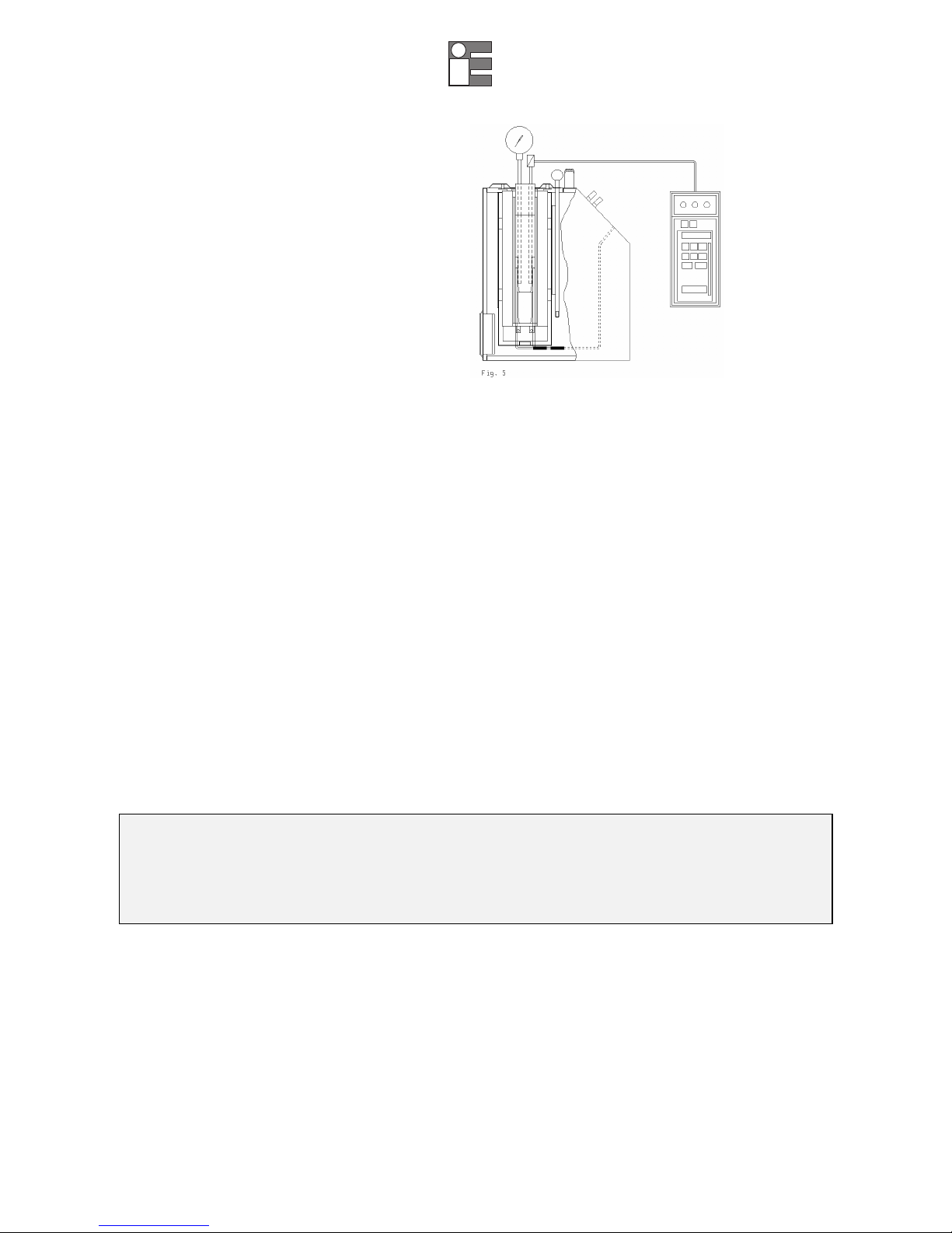
Calibration with external reference:
Make reference to the temperature value of the
external standard instrument. Put the sensitive
elements of the probes near and at the same dept
(reference to fig. 1-2-3-5).
Before any calibration follow the general recommendation:
•Starting the calibration only at ambient temperature: thermal shock can break the sensitive element of the probe and
cause harm to operator.
•To fit the equaliser block inside the oven: reference to paragraph 5.1.4.
•Put the probe to check into the equaliser block: reference to chapter 3. (fig 1-2).
•Push on the main switch (2) and waiting for the end of autotest procedure.
•Set the required temperature value on the set point (reference to paragraph 10.1):
•Press the 5key
•When the set point is changed, the temperature read on the display and that measured in the block may not
proceed at the key to increment the set point value.
•Press the 6key to decrement the set point value.
•Press the E key to confirm the chosen value
•Wait for the stabilisation of the oven before starting any calibration. ( symbol ÷ on the fist line of the display)
•To working at different temperatures set the set point at the new value and wait for the stabilisation.
•When the set point is changed, the temperature read on the display and that measured in the block may not proceed
at the same speed; this is because there are differences between the sensors used and the position of the same
inside the block.
•The temperature indicated by display must not be considered as a reference temperature but only as a general
indication of the temperature inside the block.
We suggest to insert one primary standard with SIT certificate in the block; compare the measure with the values
indicated by the standard.
Don't ever use the primary standard: it's possible to calibrate the instrument to more significant points, comparing the
displayed temperature with that temperature of standard.
ATTENTION:
AT THE END OF THE CALIBRATION DO NOT REMOVE THE PROBE IF IT IS STILL AT HIGH TEMPERATURE.ALWAYS ALLOW THE
CALIBRATOR TO COOL OFF WITH THE PROBE STILL INSERTED IN ORDER TO AVOID THERMAL SHOCK TO THE PROBE ITSELF AND HARM
TO PEOPLE OR THINGS.
BEFORE SWITCH OFF THE CALIBRATOR MAKE SURE THAT THE TEMPERATURE OF THE BLOCK IS ALMOST THE SAME AS AMBIENT
TEMPERATURE.

_________________________________________________________ _________________________________________________________
Instruction Manual MM850518 ed.01
______________________________________________19_______________________________________________
6.4 Use of the function
6.4.1 Reading the external probes
It is possible to display one or two probes tied to the EXT and REF inputs.
The following probes can be connected:
THERMOCOUPLES TYPE J, K, R, S, N with automatic compensation of connecting clamp temperature.
THERMAL RESISTANCE Pt 100 to 2, 3 or 4 wires
•Connect the probes’ terminals to the clamps as it is indicated in figure 7.
•In order to read the probes’ temperature refer to the procedure explained in paragraph 10.1 till SENSOR.; the
temperature will be displayed on the at the bottom of the display.
•In order to read in the '°F' way, refer to the procedure explained in paragraph 10.1 till Units°C/°F; the conversion of the
new scale will be carried out at once.
NOTE: The calibrator always thermally adjust the control probe situated inside the block.
6.4.2 Switch test (SW. ON SW. OFF)
It is possible to control the intervention point of thermostats by the 'SWITCH TEST' function.
•Insert the thermostat’s end in the most suitable hole of the calibrator pit (refer to notes in paragraph 3).
•Connect the thermostat’s electrical terminals to the bushes terminals (4).
•Turn the equipment on.
•Sent the thermostat intervention temperature and check the release by the lighting of the indication light (7).
•The thermostat’s release values are recorded. In order to display the recorded value, refer to the procedure explained
in paragraph 10.1 till ‘SW ON - SW OFF’.
•Press the tand 6keys at the same time in order to reset the 'SW.ON - SW.OFF' values.
•Refer to paragraph 10.1 to set the ascent and descent ramps.
6.4.3 Serial communication
On the front of the calibrator there is a 9 pole socket (5) connected to the thermoregulator, which enables the calibrator
to be completely controlled by a PC (reference to fig.8). The standard adopted RS-232 (contact the technical department
for the communication number).
The external PC must be conform to the IEC950 standard.
6.5 Re-calibration methods
To have instrument always efficient is opportune to re-calibrate it periodically.
Frequency of re-calibration is depending to the use of instrument; however we suggest to re-calibrate the furnace every
+
-
-
+
PROBE 1 PROBE 2

_________________________________________________________ _________________________________________________________
Instruction Manual MM850518 ed.01
______________________________________________20_______________________________________________
year.
This manual suits for next models
2
Table of contents
Other Eurotron Measuring Instrument manuals


