Eurotron UniCal mA User manual

EUROTRON ITALIANA s.r.l.
Viale F.lli Casiraghi 409/413
20099 Sesto S. Giovanni (MI) - Italy
Tel. +39-02-248820.1 Fax +39-02-2440286
e u r o t r o n
UniCal mA
Multifunction process current
indicator - simulator
Instruction Manual ed. 02a

_______________________________________ ______________________________________
Instruction Manual MM850099 ed.02a
_________________________________________ 2 ________________________________________
INTRODUCTORY NOTE
ATTENTION : THIS MANUAL MUST BE REFERRED TO INSTRUMENTS WITH SERIAL NUMBER FROM 002075 ONWARDS.
This publication contains operating instructions, as well as a description of the principles of operation, of
the UniCal mA portable calibrator.
The information covers all models of the instrument, including its options and accessories.
The manual is a complete "USER GUIDE", providing step-by-step instructions for operating the UniCal
mA in each of its designed functions.
The present information has been prepared for the sole purpose of assisting operating personnel in the
efficient use of the instrument.
Publication of this information does not convey any rights to use or reproduce it for any purpose other
than in connection with the installation, operation, and maintenance of the equipment described herein.
The instrument uses sophisticated analog and digital technologies.
Repair and service requires highly qualified personnel.
We will supply, on request, all pertinent instructions and procedures for service and calibration.
Our specialists will be glad to give any technical support you may require.
The instrument is powered by an internal group of four Ni-Cd rechargeable batteries. An external battery
charger module, with power voltage set at 110 or 220 V ac, is supplied as standard.
Always check battery charger data; to modify power supply , see paragraph 8.2

_______________________________________ ______________________________________
Instruction Manual MM850099 ed.02a
_________________________________________ 3 ________________________________________
INDEX
1GENERAL PERFORMANCE5
1.1 Instrument codes ------------------------------------------------------------------------------------------------6
1.2 Specifications ----------------------------------------------------------------------------------------------------7
2GENERAL FEATURES 9
2.1 Flexibility ----------------------------------------------------------------------------------------------------------9
2.2 Self calibration ---------------------------------------------------------------------------------------------------9
2.3 Keyboard ----------------------------------------------------------------------------------------------------------9
2.4 Display-------------------------------------------------------------------------------------------------------------9
2.5 Generator mode (Passive external circuit - no power supply on the external loop) --------------9
2.6 Simulator mode (Active external circuit - power supply on the external loop) ---------------------9
2.7 Measuring mode - normal -------------------------------------------------------------------------------------9
2.8 Measuring mode - power (Passive external circuit)--------------------------------------------------- 10
2.9 Power supply mode------------------------------------------------------------------------------------------ 10
2.10 IN-OUT technical unit mode (%)---------------------------------------------------------------------------10
2.11 Scale factor-----------------------------------------------------------------------------------------------------10
2.12 Square root -----------------------------------------------------------------------------------------------------10
2.13 Average mode--------------------------------------------------------------------------------------------------10
2.14 Hold function ---------------------------------------------------------------------------------------------------10
2.15 Digital interface ------------------------------------------------------------------------------------------------10
2.16 Case-------------------------------------------------------------------------------------------------------------- 10
3PHYSICAL DESCRIPTION 12
4FUNCTIONAL DESCRIPTION 13
4.1 Power supply--------------------------------------------------------------------------------------------------- 13
4.2 Operative keyboard -------------------------------------------------------------------------------------------13
4.3 Input circuit -----------------------------------------------------------------------------------------------------14
4.4 Microprocessor ------------------------------------------------------------------------------------------------14
4.5 Firmware --------------------------------------------------------------------------------------------------------14
4.6 Digital display --------------------------------------------------------------------------------------------------14
4.7 Digital to analog converter ----------------------------------------------------------------------------------15
4.8 Serial digital interface ----------------------------------------------------------------------------------------15
4.9 Battery charger. Operation from line source. ----------------------------------------------------------- 15
5UNPACKING 16
6PRE-OPERATIONAL CHECK 17
7ELECTRICAL CONNECTIONS (INPUT-OUTPUT) 18
7.1 Wiring practice-------------------------------------------------------------------------------------------------18
8OPERATIONS & APPLICATIONS 20
8.1 Rechargeable batteries --------------------------------------------------------------------------------------20
8.2 Battery charger. Power supplied from power line ac --------------------------------------------------20
8.3 Power "ON" -----------------------------------------------------------------------------------------------------20
8.4 Battery voltage indication.----------------------------------------------------------------------------------- 21
8.5 Operating mode set-up -------------------------------------------------------------------------------------- 21
8.5.1 IN / OUT function selection ----------------------------------------------------------------------------- 21
8.5.2 Parameter selection--------------------------------------------------------------------------------------- 22
8.5.3 Average readings------------------------------------------------------------------------------------------ 22
8.5.4 Hold function -----------------------------------------------------------------------------------------------23
8.5.5 IN / OUT data memories---------------------------------------------------------------------------------23
8.5.6 STEP increment -------------------------------------------------------------------------------------------23
8.5.7 "Scale factor" mode--------------------------------------------------------------------------------------- 24
8.5.8 mA - % selection ------------------------------------------------------------------------------------------ 24

_______________________________________ ______________________________________
Instruction Manual MM850099 ed.02a
_________________________________________ 4 ________________________________________
8.6 Faulty operating conditions ---------------------------------------------------------------------------------24
8.7 Digital interface ------------------------------------------------------------------------------------------------ 25
8.7.1 Digital interface program mode ------------------------------------------------------------------------ 25
8.7.2 Digital output wiring practice---------------------------------------------------------------------------- 26
8.7.3 Adaptor ( TTL to RS 232 )-------------------------------------------------------------------------------26
8.7.4 Communication protocol from UniCal mA to a computer -------------------------------------- 27
8.7.5 Computer request for UniCal settings ----------------------------------------------------------------28
8.7.6 Communication programs------------------------------------------------------------------------------- 29
9MAINTENANCE 31
9.1 Safety recommendations ------------------------------------------------------------------------------------31
9.2 Spare parts and accessories -------------------------------------------------------------------------------31
9.3 Storage ----------------------------------------------------------------------------------------------------------31
10 CERTIFICATES 32
10.1 Certificate of warranty---------------------------------------------------------------------------------------- 32
10.2 Certificate of Conformity-------------------------------------------------------------------------------------32
11 SUPPORT DOCUMENTATION ERRORE. IL SEGNALIBRO NON È DEFINITO.
APPENDIX ERRORE. IL SEGNALIBRO NON È DEFINITO.

_______________________________________ ______________________________________
Instruction Manual MM850099 ed.02a
_________________________________________ 5 ________________________________________
1GENERAL PERFORMANCE
The portable indicator - simulator UniCal mA is an instrument designed to perform, in a modern and
practical way, all the most popular process current check-outs and calibration, both in laboratory and
field work.
The current signal levels are those normally used on instruments, components and systems for
industrial process control.
Accurate, compact, rugged, easy to use the UniCal mA represents the ideal solution for measurement
and simulation inside both passive and active external circuits with five different modes of operation:
- Generator mode
-Simulator mode
- Normal measuring mode
-Loop powered measuring mode
- 24V dc power supply
The microprocessor technology provides high accuracy on extended ranges and carries out
mathematical computation (average, scale factor, square root) to simplify operator use.
The selection of operating mode is made on a polycarbonate membrane keyboard which assures up to
one million operations per key.
The measured or the simulated value is indicated on a high quality LCD dot matrix display which
provides good contrast even in poor light conditions.
A menu-driven set-up allows the generation of a single value, and the storage of three values with
manual recall .
A manual repeat measurement is also possible (<STEP> key).
The case, made of shock-resistant and self-extinguishing ABS, is ergonomically designed for easy and
practical operations.
The instrument is powered by four Ni-Cd rechargeable batteries AA (1,25V) with an external battery
charger supplied as a standard accessory.

_______________________________________ ______________________________________
Instruction Manual MM850099 ed.02a
_________________________________________ 6 ________________________________________
1.1 Instrument codes
UniCal mA - A
Basic configuration of the instrument includes a soft vinyl carrying case with shoulder strap and an
instruction manual.
Table A Power supply
1 120V ac 50/60 Hz - USA plug
2 230V ac 50/60 Hz - Schuko plug
3 240V ac 50/60 Hz - UK plug
4230V ac 50/60 Hz - European plug
9Special

_______________________________________ ______________________________________
Instruction Manual MM850099 ed.02a
_________________________________________ 7 ________________________________________
1.2 Specifications
•IN / OUT parameter
mA and %
•Ranges:
from 0.00 to 22.00 mA
from 4.00 to 20.00 mA
•Resolution:
0.01 mA or 0.1%
•Limits of error:
±0.05% of the reading +10µA
(The limits of error are defined at the ambient temperature of 23°C ±2°C for 30 days without the use
of the autocalibration program)
•mA to % conversion :
linear or square
•Common mode rejection:
>130 dB at 50/60 Hz
•Normal mode rejection:
>60 dB at 50/60 Hz
•Temperature stability:
span: ±0,0125% of the reading/°C
zero ±2 µA /°C
•Internal shunt resistance:
< 50Ω
•Output impedance:
Max 1 k Ω(20 mA with internal feeder 24V dc)
•Power supply for external loop:
24V dc with maximum current of 22 mA
•Display:
high contrast dot matrix alphanumeric LCD display (7x5 dots per character - 16 characters)
•Display contrast:
4 step keyboard setting
•Scale factor:
Zero and span programmable within -10000 and +10000
•Square root:
in combination with scale factor (display limits 0 and+2500)
•Calibration:
automatic procedure
•Input protection:
up to 150V with special fuse + electronic protection
•Power supply:
n. 4 AA alkaline batteries or Ni-Cd rechargeable batteries 1.25V 0.7 A/hour
•Digital interface:
TTL logic levels
An adaptor from TTL to RS232 is available on request
•Battery life:
Ni-Cd 8 hours, Alkaline 16 hours continuous operation
•Battery level indication:
low battery symbol
•Battery charger module:
supplied as a standard accessory
•Recharge time:
8 hours to 90% with instrument switched -OFF-
•Batteries voltage:

_______________________________________ ______________________________________
Instruction Manual MM850099 ed.02a
_________________________________________ 8 ________________________________________
5,2 V (nominal)
•Program release identification:
release code on the display
•Operating environment temperature range:
from -5°C to +50°C
•Storage temperature range:
from -20°C to 60°C
•Case:
ABS
•Dimensions:
210 x 96 x 40 mm
•Weights:
net 0,9 Kg
gross with packaging 1,2 Kg

_______________________________________ ______________________________________
Instruction Manual MM850099 ed.02a
_________________________________________ 9 ________________________________________
2GENERAL FEATURES
2.1 Flexibility
Advanced flexibility of performance has been achieved using microprocessor technology.
The indicator-simulator UniCal mA is a complete system for check outs, measurements and calibrations
built into a single compact portable instrument.
The simulated or measured values can be directly indicated in electrical units (mA) or technical units
(%).
2.2 Self calibration
The hardware-firmware design allows for an automatic calibration of the instrument.
A precise source of 20mA dc is the only required standard reference.
The calibration procedure is protected by a security code.
2.3 Keyboard
A tactile polycarbonate membrane keyboard, with a working life of one million operations per key, seals
the internal electronics from the surrounding environment.
It allows the selection of the operative mode and the setting of simulation value with fast and slow
upgrading.
Contact closure of membrane keys is acknowledged, as a coded signal, directly by the microprocessor
2.4 Display
The high quality alphanumeric LCD display (7x5 dot matrix per character - 16 characters) allows easy
readings even in poor light conditions.
The operative mode (measurement or simulation), the technical unit and the signal value are
simultaneously indicated.
2.5 Generator mode (Passive external circuit - no power supply on
the external loop)
The instrument generates a current signal (ranging from 0,00 mA to 22,00 mA dc) into a passive circuit
to calibrate recorders, controllers, indicators, actuators, etc.
2.6 Simulator mode (Active external circuit - power supply on the
external loop)
Simulates the output of a 2-wire transmitter (0,00 to 22,00 mA dc) in a loop with external power.
2.7 Measuring mode - normal
Reads dc current directly in milliamperes or in technical units (%)

_______________________________________ ______________________________________
Instruction Manual MM850099 ed.02a
_________________________________________ 10 ________________________________________
2.8 Measuring mode - power (Passive external circuit)
The instrument provides 24V dc power for operating a 2-wire transmitter and, simultaneously, reads the
loop current in percent (-25.0 to +100,0%) or milliamperes (0.00 to 20.00 mA).
2.9 Power supply mode
The instrument can be used as a loop power source (24V dc with a maximum current of 22 mA).
2.10 IN-OUT technical unit mode (%)
The instrument converts the voltage signal into %, or vice-versa, with the following linear relation:
0 4 12 20
-25.00% 0.00% +50.00% +100.00%
2.11 Scale factor
Easy menu-driven set-up to read or simulate electrical signal value in terms of technical units (i.e. bar,
% CO, RH, etc.).
2.12 Square root
Can be programmed during the set up procedure (linear ranges only) e.g. to obtain direct readings of
flow from a dP transmitter signal.
The display limits are 0 to +2500.
2.13 Average mode
For the measurements of unstable input signals by a progressive averaging of a programmable number
of conversions (approximately 10 seconds)
2.14 Hold function
To freeze on the display the last measured value.
2.15 Digital interface
A digital interface, with TTL logic levels, is available as standard for communications with external units.
A 4 wire cable, with a male mini connector, and an auxiliary module for TTL to RS232 conversion is
available as an option.
2.16 Case

_______________________________________ ______________________________________
Instruction Manual MM850099 ed.02a
_________________________________________ 11 ________________________________________
The case, made of shock-resistant and self-extinguishing ABS, is ergonomically designed for easy
practical operation.
The instrument is supplied in a vinyl protective case with carrying strap for easy transportation.

_______________________________________ ______________________________________
Instruction Manual MM850099 ed.02a
_________________________________________ 12 ________________________________________
3PHYSICAL DESCRIPTION
The UniCal mA portable calibrator consists of a rugged and compact case, a mother board with all
base functions, a tactile polycarbonate membrane keyboard, an LCD display and a group of four Ni-Cd
rechargeable batteries.
The battery container is located on the back of the case and is accessible by sliding and removing the
plastic cover.
The case has been designed and manufactured using modern CAD/CAM techniques giving
consideration to the manufacturing process and ergonomic characteristics for easy operation and
transportation.
The two halves of the case are joined together by five metal screws located on the back side.
The vinyl case, with shoulder strap, assures better protection of the instrument against knocks or
scratches.
_______________________________________ ______________________________________
Instruction Manual MM850099 ed.02a
_________________________________________ 13 ________________________________________
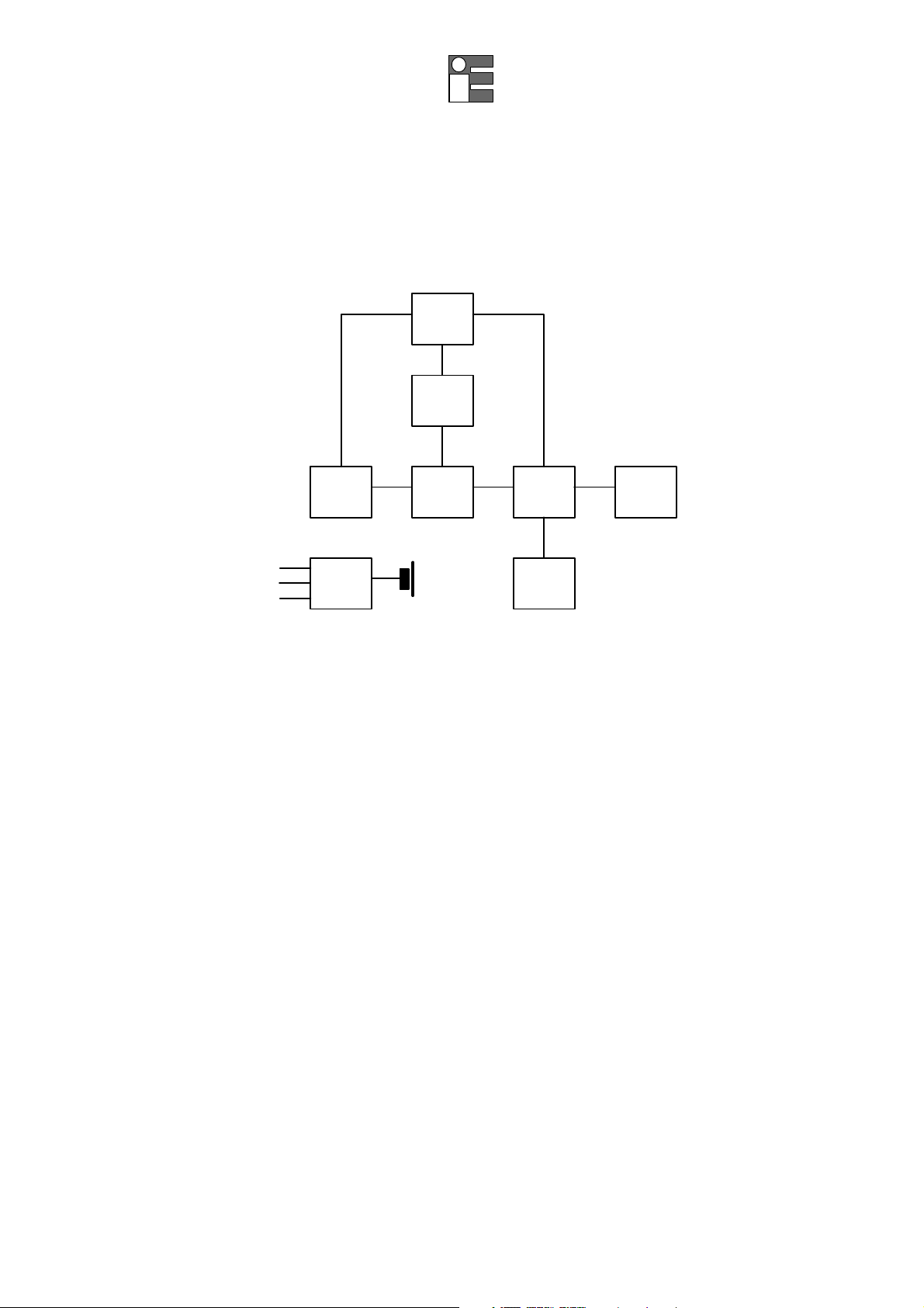
4FUNCTIONAL DESCRIPTION
The block diagram of the UniCal mA portable calibrator is shown in the figure below:
D/A
Ref.
A/DIN/OUT µPDisplay
KeyboardP.S.
+5V
-5V
+24V
The functional blocks of the instrument are as follows:
•power supply
•microprocessor (central unit + memory)
•input circuit
•LCD display
•membrane keyboard
•output circuit
4.1 Power supply
The instrument is powered if not otherwise specified with the order, by four internal batteries that can be
recharged through an external charger module supplied as a standard accessory.
The internal batteries are Ni-Cd rechargeable AA type with a nominal voltage of 1.25 V.
A section of the power supply circuit enables following voltages function :
+ 5 V logic and analog circuits
- 5 V analog circuits
A second section of the power supply circuit, configurated as a voltage multiplier generates a voltage
level of 24 V dc to interface a maximum resistance of 1000 ohm with a current simulation of 20mA.
4.2 Operative keyboard
The front panel is a tactile polycarbonate membrane keyboard, and has a working life of one million
operations per key.
The contact closure of the membrane keyboard keys is acknowledged as a coded signal by the
microprocessor which recognizes the operators instruction.

_______________________________________ ______________________________________
Instruction Manual MM850099 ed.02a
_________________________________________ 14 ________________________________________
ON power -ON- key
OFF power -OFF- key
t/ ssimulation value cursors (1 L.S.D. step)
STO memory load keys
STEP step value setting on ramp simulation
0, 1, 2 IN - OUT memories
SELECT set-up procedure
AVERAGE average measurements
IN/OUT IN-OUT mode selection
LCD± display contrast adjustment
HOLD last measured value display hold
%technical unit selection
mA electrical unit selection
ENTER memory load key
SHIFT key secondary function
FAST cursor accelerator (L.S.D. x 100)
A "bip" sound indicates that the instrument has received and
acknowledged the operators instruction.
4.3 Input circuit
This input circuit is based on two shunt resistors to convert the current signal to voltage signal.
The voltage signal is converted from analog to digital with a dedicated integrated circuit.
4.4 Microprocessor
The microprocessor handles all the logic functions of the instrument, drives the digital display and
acknowledges all operator instructions.
The heart of the circuit is a single-chip microcomputer (68HC705C8) that utilizes HCMOS technology to
provide the low power characteristics and high noise immunity of CMOS plus the high speed operation of
HMOS.
The above circuit incorporates a watchdog feature to reset normal operation in case of program blocks
caused by external high energy interferences and two serial communication subsystems (SCI and SPI).
4.5 Firmware
The operating system firmware handles all logic instructions to the internal peripheral circuits and
performs the computation of scale factor and square root.
The application system firmware is resident on the non-volatile memory (EEPROM) on the
microprocessor chip.
It is used to store the installation parameters (autocalibration data, programs data, etc.)
4.6 Digital display
The digital display, mounted on an auxiliary board, uses high contrast LCD technology .

_______________________________________ ______________________________________
Instruction Manual MM850099 ed.02a
_________________________________________ 15 ________________________________________
The character generation is by a dedicated secondary microprocessor driven by the bus of the main
microprocessor.
The 16 characters are displayed with a 7 x 5 dot matrix.
4.7 Digital to analog converter
The digital to analog is based on a special reconfiguration of the A/D integrated circuit.
A section of the analog switch and output amplifier are also operative.
4.8 Serial digital interface
The serial digital interface circuit is essentially based on the serial communication interface subsystem
(SCI) on the chip of the microprocessor at 0 to +5V level.
An adaptor to convert TTL to RS 232 voltage levels can be obtained on request.
4.9 Battery charger. Operation from line source.
The auxiliary module, supplied as a standard accessory, allows operation from 110-120 or 220-240 V ac
50/60 Hz.
The calibrator, if needed, can be operated directly from a line source through the charger.
The plastic case of the battery charger incorporates the line voltage plug and cable for connection to the
instrument.
The charger circuit is designed with an insulating transformer and a voltage stabilizer circuit.
The step-down transformer reduces the power line (110-120 Vac or 220-240 Vac nominal) to a value of
10 Vac.
The above voltage is full wave rectified, filtered and stabilized.
The output voltage of 6.45 Vdc is the ideal value to recharge the internal Ni-Cd batteries.

_______________________________________ ______________________________________
Instruction Manual MM850099 ed.02a
_________________________________________ 16 ________________________________________
5UNPACKING
Remove the instrument from its packing case and remove any shipping ties, clamps, or packing
materials.
Carefully follow any instructions given on any attached tags.
Inspect the instrument for scratches, dents, damage to case corner etc. which may have occurred during
shipment.
If any mechanical damage is noted, report the damage to the shipping carrier and then notify
EUROTRON directly or its nearest agent, and retain the damaged packaging for inspection.
A label, inside the battery container, indicates the serial number of the instrument.
Refer to this number for any enquiry for service, spare parts supply or application and technical support
requirements.
EUROTRON will keep a data base with all information regarding your instrument.

_______________________________________ ______________________________________
Instruction Manual MM850099 ed.02a
_________________________________________ 17 ________________________________________
6PRE-OPERATIONAL CHECK
The instrument is powered by four Ni-Cd rechargeable batteries.
The external battery charger, supplied as standard, may be ordered for either 110-120 Vac or 220-240
Vac power source.
To modify the charger's power voltage follow the instructions in par. 8.2.
Before the first use of the instrument carefully verify the nominal voltage value of the charger; in case of
modification do not forget to correct the pertinent label.
The instrument should be used in environments where the temperature does not exceed the specified
limits (from –5°C to +50°C) and where the relative humidity is lower than 95%.
I n 0. 00 V
In case of "low" battery condition (voltage lower than 4.5 V ±0.1 V) the display will show the appropriate
symbol
An empty symbol means that the battery package has enough energy to operate for 30 minutes
operation.
A black symbol means that batteries charge is below the minimum acceptable level : operation of the
instrument is no longer possible.
In this condition the batteries must be recharged.
WARNING.
THE INSTRUMENT SUPPLIED WITH NI- CD RECHARGEABLE BATTERIES.
DO NOT USE NORMAL ALKALINE BATTERIES.
ALKALINE BATTERIES, WHEN CONNECTED TO A DC VOLTAGE SUPPLY, UNDERTAKE AN OVERHEATING PROCESS WITH A
RISK OF EXPLOSION.

_______________________________________ ______________________________________
Instruction Manual MM850099 ed.02a
_________________________________________ 18 ________________________________________
7ELECTRICAL CONNECTIONS (input-output)
Make sure that IN/OUT terminals are connected with the correct polarity.
7.1 Wiring practice
Although the UniCal mA portable calibrator is designed to be insensitive to transients or noise, the
following recommendations should be followed to reduce ac pick up in the signal leads and to ensure
good performance.
The input leads should not be run near ac line wiring, transformers and heating elements.
Input/output leads should, if possible, be twisted and shielded with the shield grounded at the end of the
cable.
When shielded cables are used the shield must be connected to the positive terminal.
GENERATOR MODE
(PASSIVE EXTERNAL
CIRCUIT)
Indicator
+ -
P.S.TRX
+-
Indicator
+ -
P.S.TRX
+-
MEASURING MODE
Indicator
+ -
P.S.TRX
+-
Indicator
+ -
P.S.TRX
+-
GENERATOR MODE
POWER
(PASSIVE EXTERNAL
CIRCUIT)
Indicator
+ -
P.S.TRX
+-
Indicator
+ -
P.S.TRX
+-
SIMULATOR MODE
(ACTIVE EXTERNAL
CIRCUIT)
Indicator
+ -
P.S.TRX
+-
Indicator
+ -
P.S.TRX
+-
POWER SUPPLY MODE
Indicator
+ -
TXR

_______________________________________ ______________________________________
Instruction Manual MM850099 ed.02a
_________________________________________ 19 ________________________________________
The fig.7.1 shows some examples of input/output wiring and connections.

_______________________________________ ______________________________________
Instruction Manual MM850099 ed.02a
_________________________________________ 20 ________________________________________
8OPERATIONS & APPLICATIONS
The UniCal mA portable calibrator has been factory calibrated before shipment.
During start-up the operator should only select and load the pertinent application parameters as
described in the following paragraphs.
8.1 Rechargeable batteries
The instrument is powered by four built-in rechargeable batteries.
The instrument is shipped with an average level of charge.
After unpacking, a full charge of the batteries is recommended; connect the instrument to the charger
module ("OFF" condition) for a minimum period of 12 hours .
The Ni-Cd rechargeable batteries do not suffer when used in cyclic operations.
Cyclic operation is understood as a method of operation by which the battery is continually charged and
discharged.
Note that a battery, at its lower limit of charge, risks a non uniform cell polarization: this condition makes
it difficult to recharge with the charger supplied.
Avoid leaving the instrument, with batteries totally or partially discharged, for a long time without
recharging.
To charge the batteries use only the original supplied charging module. The module incorporates
protection and current limiting devices not normally found in other commercial chargers.
8.2 Battery charger. Power supplied from power line ac
The external battery charger is configured, before shipment, for a mains supply of 110-120 V ac or 220-
240 Vac, upon order specification.
The nominal voltage value is indicated on the front label of the charger; if the power supply voltage has
to be modified, correct the indication on the front label.
To replace the power plug loosen the three bottom screws.
To modify the power supply voltage place the jumper, mounted on the circuit board of the charger, as
indicated in figure:
Jumper A
power line at 220-240 V 50/60 Hz
Jumpers B and C
power line at 110-120 V 50/60 Hz
8.3 Power "ON"
ATTENTION : ALL VALUES IN THE FOLLOWING FIGURES ARE ONLY LISTED AS AN EXAMPLE.
During set-up and load memory remember that the instructions of the manual related to key operation
have the following meaning:
<A> + <B> Press the <A> key and keeping the pressure on the key, press then the <B> key
<A>, <B> Press in sequence first the <A> key and then the <B> key.
"A"
"B"
"C"
Table of contents
Other Eurotron Measuring Instrument manuals


