Eurotron MicroCal 20 Series User manual
ENGLISH
http://www.eurotron.com
M
Mi
ic
cr
ro
oC
Ca
al
l
2
20
0
I
IS
S
M
Mi
ic
cr
ro
oC
Ca
al
l
2
20
0
S
Se
er
ri
ie
es
s
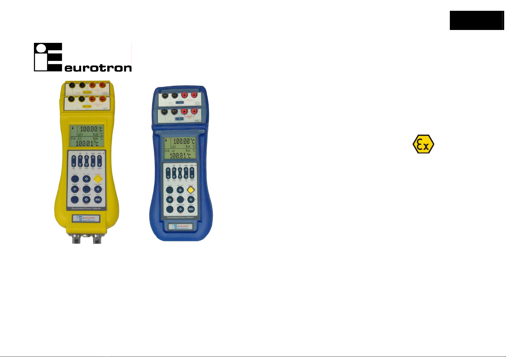
2 channels multifunction calibrators
MicroCal 20 - MicroCal 20 IS
MicroCal P20 - MicroCal P20 IS
MicroCal 20T
Instruction Manual
MM850432 ed. 05c

Instruction Manual MM850432 ed. 05c
2
INTRODUCTORY NOTE
ATTENTION:THIS MANUAL MUST BE REFERRED TO INSTRUMENTS WITH SERIAL NUMBER 62768 AND FIRMWARE VERSION 6.018 ONWARDS.
This manual has been with all the information you need to install, operate and maintain the two channels multifunction Calibrators MicroCal 20
series and its accessories.
Eurotron has used the best care and efforts in preparing this book and believes the information in this publication are accurate. The Eurotron
products are subjected to continuous improvement, in order to pursue the technological leadership; these improvements could require changes to
the information of this book.
Eurotron reserves the right to change such information without notice.
No part of this document may be stored in a retrieval system, or transmitted in any form, electronic or mechanical, without prior written permission
of Eurotron Instruments S.p.A.
MicroCal 20 DPC Calibrator uses sophisticated analogic and digital technologies. Any maintenance operation must be carried out by qualified
personnel ONLY. Eurotron supplies instructions and operative procedures for any operation on the instrument. We recommend to contact our
technicians for any support requirements.
MicroCal 20 DPC is fully tested in conformity with the directive n°89/336/CEE Electromagnetic Compatibility. Eurotron shall not be liable in any
event, technical and publishing error or omissions, for any incidental and consequential damages, in connection with, or arising out of the use of
this book.
All right reserved
Copyright © 2004, 2008
EUROPEAN Headquarters
Eurotron Instruments SpA
Viale F.lli Casiraghi 409/413
20099 Sesto S. Giovanni (MI)
Tel. : +39-02 24 88 201
FAX: +39-02 24 40 286
USA Headquarters
E-Instruments Group LLC
172 Middletown Blvd – Suite B201
Langhorne, PA 19047
Tel.: 215 750 1212
FAX: 215 750 1399

Instruction Manual MM850432 ed. 05
3
CONTENTS
1IMPORTANT NOTE .............................5
1.1 Safety warning ............................................5
1.2 Warnings for IS models............................... 6
2GENERAL ............................................7
2.1 Ordering code .............................................8
2.2.1 MicroCal 20 DPC codes ......................... 8
2.2.2 MicroCal 20T codes ............................... 9
2.2.3 MicroCal P20 codes ............................. 10
2.3 Accessories............................................... 11
2.4 Technical specifications ............................ 12
2.4.1 MicroCal 20 DPC ................................. 12
2.4.2 MicroCal P20........................................ 16
2.4.3 MicroCal 20T........................................ 19
3DESCRIPTION...................................22
3.1 Keyboard .................................................. 26
3.2 Display ...................................................... 27
3.3 Power supply ............................................ 28
3.4 Electrical connections ...............................28
3.4.1 Multi-connection binding post............... 31
4GETTING STARTED..........................32
4.1 Unpacking ................................................. 32
4.2 Charge the battery .................................... 32
4.3 Power up................................................... 32
4.4 Automatic channel protections .................. 32
4.5 Date and time setting ................................ 33
4.6 Using the backlight.................................... 34
4.7 Adjust the display contrast ........................ 35
4.8 Change display mode ............................... 35
5OPERATIONS....................................37
5.1 Data Hold .................................................. 37
5.2 Zeroing measure....................................... 37
5.3 Storing ...................................................... 37
5.4 Calculator.................................................. 38
5.5 Measure mode .......................................... 39
5.5.1 Temperature with Thermocouples........ 39
5.5.2 External Cold Joint Reference Setting . 40
5.5.3 Temperature with RTDs ....................... 41
5.5.4 Temperature Scale Setting................... 43
5.5.5 Temperature Unit Setting ..................... 44
5.5.6 Current ................................................. 44
5.5.7 Voltage................................................. 46
5.5.8 Math Functions .................................... 47
5.5.9 Pressure............................................... 49
5.5.10 Pressure Unit Setting ........................... 49
5.5.11 Pressure Zeroing ................................. 50
5.5.12 Resistance ........................................... 50
5.5.13 Frequency/Pulse: measure .................. 52
5.6 Source mode: signals generation ............. 53
5.6.1 Temperature generator: MicroCal T
series 54
5.6.2 Frequency/Pulse: generation ............... 55
5.7 X-Scaling setting....................................... 56
5.8 Cycle & Ramp........................................... 57
5.9 Data Logging ............................................ 60
5.10 Graph ................................................... 60
5.11 Transmitter simulator ........................... 61
5.12 Memory Scan....................................... 61
5.13 Switch Test .......................................... 63
5.14 Leak Test ............................................. 64
5.14.1 Leak Test: file....................................... 65
5.15 Alarms.................................................. 66
5.16 Switching on settings (Power On) ........ 67
6SERIAL COMMUNICATION..............68
6.1 RS232 communication port....................... 68
6.2 Baud Rate setting ..................................... 68
6.2 Firmware upgrade : STFlash .................... 69
7RS232 – USB ADAPTOR
INSTALLATION SETUP.................................71
7.1 Installing driver for the RS232/USB adaptor
71
8SOFTWARE.......................................74
8.1 MicroCal 20 DPC Utilities Manager .......... 74
8.1.1 Data logger: data storing...................... 76
8.1.2 Data logger: data simulation (Replay).. 77
8.1.3 LogMan ................................................ 78
8.1.4 Certificates ........................................... 81
8.1.5 Linearization functions: LinMan............ 83
8.2 CalpMan 2007: Off-Line procedures......... 86
8.2.1 Transfer calibration parameters ........... 87
9CALIBRATION PROCEDURES ........89
10 DLL DRIVER FOR WINDOWS™.......92
10.1 Function and Property.......................... 92
10.1.1 Directory of publics methods available
OnLine 92
10.2 Performances ...................................... 92
10.3 Interfaces ............................................. 93
10.3.1 Indication of the instrument.................. 93
10.3.2 Compatibility with VC++, VBasic e .NET
93
10.3.3 Driver function structure....................... 94
10.4 Data ..................................................... 95
10.4.1 Data structure ...................................... 95
10.4.1.1 InstrumentFile ................................. 95
10.4.1.2 Methods Setchn .............................. 96
10.4.1.3 Methods Getmeas_output............... 97
10.5 Configuration ....................................... 98
10.5.1 Operating mode ................................... 98
10.6 Development environment ................... 98
10.6.1 Compiler .............................................. 98
11 APPLICATIONS.................................99
11.1 Calibrating a temperature indicator...... 99
11.2 Calibrating a TC temperature transmitter
100
11.3 Calibrating a pressure transmitter...... 102
11.4 RTDs certifications............................. 103
12 FLOW-CHARTS...............................104
12.1 Menu key ........................................... 104
12.2 Select key .......................................... 106
12.2.1 Settings Channel 1............................. 106
12.2.2 Settings Channel 2............................. 107
12.2.3 Settings Pressure channel ................ 109
12.3 Cal Proc key ...................................... 109
12.4 Display key ........................................ 109
13 MAINTENANCE...............................110
13.1 Error messages ................................. 110
13.2 Status page........................................ 111
13.3 Protections......................................... 111
13.4 Storage .............................................. 111
13.5 Spare parts ........................................ 111

Instruction Manual MM850432 ed. 05c
4
14 CERTIFICATES ...............................112
14.1 Warranty terms ...................................112
14.2 Letter of conformity.............................112
15 INTRINSIC SAFETY SUPPLEMENT
114
15.1 IS model specifications.......................114
15.2 ATEX Specifications...........................115
15.3 Instructions for use .............................116
15.3.1 Recharging the batteries ....................116
15.3.2 Battery maintenance ..........................117
15.3.3 Battery pack replacement...................117
16 CERTIFICATES ...............................118
16.1 Warranty terms................................... 118
16.2 Consumer notice ................................ 118
16.3 Letter of conformity ............................ 118

Instruction Manual MM850432 ed. 05
5
1 IMPORTANT NOTE
Unless otherwise indicated in the text, the operating instructions contained in this publication apply to both the MICROCAL 20 DPC Multi-Calibrator instruments and the
MICROCAL 20 DPC IS Multi-Calibrator instruments.
MICROCAL 20 DPC IS IMPORTANT NOTICE !
ONLY THE INTRINSICALLY SAFE VERSION OF THIS MULTI-CALIBRATOR INSTRUMENT (MICROCAL 20 DPC IS) MAY BE USED IN HAZARDOUS AREAS AND THE FOLLOWING GENERAL WARNINGS AND
CONDITIONS OF USE SUMMARIZED BELOW ARE APPLICABLE.PAGES 113 TO 116 PROVIDE SUPPLEMENTARY INFORMATION FOR THE INTRINSICALLY SAFE VARIANTS
BEFORE USING MICROCAL 20 DPC IS, INTRINSICALLY SAFE VERSIONS OF THIS MULTI-CALIBRATOR,READ THE FOLLOWING WARNINGS AND READ AND FULLY UNDERSTAND THE SPECIAL
CONDITIONS OF USE DETAILED IN THE CHAPTER 15 OF THIS MANUAL.
IF UNSURE, CHECK BEFORE USE.
1.1 Safety warning
HIGH-PRESSURE
UNCONTROLLED RELEASE OF HIGH PRESSURE IS HAZARDOUS TO PERSONEL AND MAY CAUSE DAMAGE TO EQUIPMENT.BEFORE CONNECTION OF ANY PRESSURE COMPONENT TO THE CALIBRATOR BE
SURE THAT THE COMPONENTS ARE ISOLATED FROM THE PRESSURE SUPPLY AND ANY INTERNAL PRESSURE IS RELEASED SLOWLY.
!WARNING !
DON'T APPLY A PRESSURE HIGHER THAN 125% FULL SCALE TO THE CALIBRATOR.
IF AN EXCESSIVE PRESSURE,HIGHER THAN THE STATED ONE,IS APPLIED,PERSONNEL MAY RECEIVE INJURIES THAT COULD,IN EXTREME CIRCUMSTANCES BE LETHAL.FURTHERMORE,POSSIBLE
SERIOUS DAMAGES CAN OCCUR TO THE INSTRUMENT,THE USER’S SYSTEM AND EQUIPMENT.
RECHARGEABLE NI-MH BATTERIES
RECHARGEABLE BATTERIES MUST BE RECYCLED OR DISPOSED FOR PROPERLY.MAY EXPLODE IF DAMAGED OR DISPOSED OF IN FIRE.DO-NOT SHORT-CIRCUIT.
CAUTION: USE CHARGER SUPPLIED BY EUROTRON INSTRUMENTS ONLY.
!WARNING !
PRIMARY ELEMENTS (I.E.THERMOCOUPLES,RESISTANCE THERMOMETERS,ETC.) ARE NORMALLY LINKED TO ELECTRICAL POTENTIALS EQUAL OR NEAR TO THE GROUND POTENTIAL.HOWEVER,IN
SOME APPLICATIONS,THERE MAY BE PRESENT A COMMON MODE VOLTAGE TO EARTH.
CHECK FOR VOLTAGE BETWEEN INPUT TERMINALS AND GROUND,AS THIS VOLTAGE CAN BE TRANSMITTED TO OTHER DEVICES CONNECTED TO THE CALIBRATOR.

Instruction Manual MM850432 ed. 05c
6
1.2 Warnings for IS models
1. DO NOT exceed the maximum measurement ratings given on chapter 15 of this manual.
2. DO NOT open the instrument case in a hazardous area.
3. Batteries must ONLY be fitted in a SAFE AREA.
4. If fitted with rechargeable batteries, the batteries must ONLY be charged in a safe area and only with the Eurotron charger supplied for use with the Multi-Calibrator.
5. The RS232 communication circuit may only be used outside the hazardous area.
6. When the Multi-Calibrator, Type MICROCAL 20 DPC IS, is used as a source for intrinsically safe apparatus, that apparatus may not be connected to any other intrinsically
safe circuit simultaneously. The parameters of the apparatus must comply with the output parameters of the Multi-Calibrator.
7. To prevent electrical shocks or damage to the instrument, do not connect more than 30 V between the terminals, or between the terminals and the ground (earth).
The Intrinsic Safety for zone 0 with ATEX certification, class II 1G EEx ia IIC T4 is available. (-20°C from T Ambient to + 50°C)

Instruction Manual MM850432 ed. 05
7
2 GENERAL
MicroCal 20 DPC series are two insulated channels, multifunction calibrators. They are hand-held instruments developed to meet all the needs of instrumentation engineers and
Quality managers, both in laboratory and in fieldwork. These units are accurate, rugged, compact and easy to use. They are the best solution to simulate and measure electrical
and physical parameters: Voltage, current, resistance, thermocouple, resistance thermometers, pressure, frequency and pulse.
Advanced flexibility and high performance has been achieved using 32-bit microprocessor and a fast A/D conversion technology. The calibrators memory, has stored inside all data
for normalised IEC, DIN and JIS thermoelectric sensors for both IPTS68 and ITS90 International Temperature Scale. The microprocessor performs automatic linearization and cold
junction compensation to assure high accuracy. It is possible to set the calibrator to execute menu-driven calibration procedure for your instruments in fieldwork.
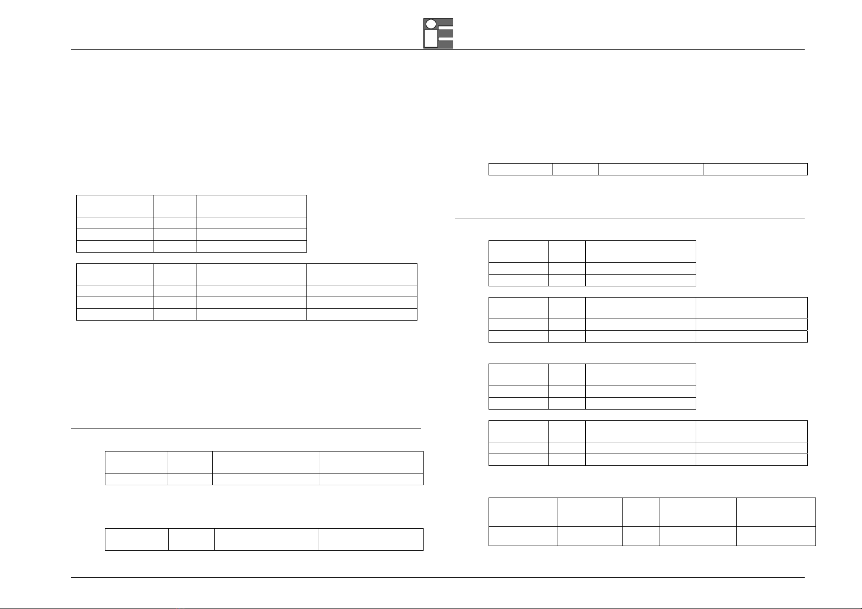
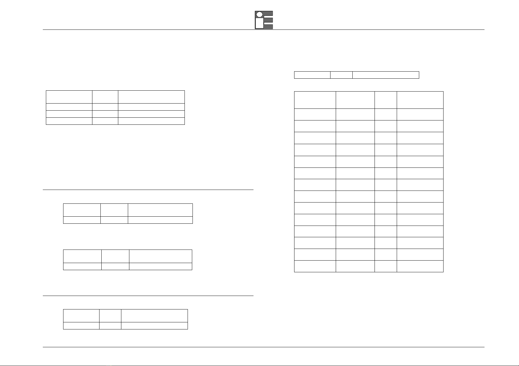
7 different models are available to meet different needs about test and calibration:
Model CH1 CH2 Internal External Basic HART EC
pressure pressure Accuracy protocol module
MicroCal 20 DPC basic IN OUT NO OPT. ±0.02% rdg OPT. OPT.
MicroCal 20 DPC plus IN OUT OPT. OPT. ±0.01% rdg OPT. OPT.
MicroCal 20 DPC XP IN IN/OUT OPT. OPT. ±0.006% rdg OPT. OPT.
MicroCal P20 basic NO NO OPT. OPT. ±0.01% rdg OPT. OPT.
MicroCal P20 plus IN (V, mA) NO OPT. OPT. ±0.01% rdg OPT. OPT.
MicroCal 20T IN IN NO NO ±0.01% rdg OPT. OPT.
Both Channel 1 (IN) and Channel 2 (IN/OUT) have the following operative mode capability: millivolts, volts, milliamperes (active and passive loop), ohms, temperature with
thermocouples, temperature with resistance thermometers, frequency, and pulse.
Optional single or dual sensors Pressure inputs can be installed inside the calibrator for gauge, absolute and differential measurements.
An external pressure sensor can be installed for measurements up to 700 bar.
Optional auxiliary measurements (EC module) with integrated sensors are: Relative humidity and temperature, Barometric pressure sensor.
Report of Calibration
Each MicroCal is factory calibrated and certified against Eurotron Standards, which are periodically certified by an Internationally recognised Laboratory to ensure traceability, and
shipped with a Report of Calibration stating the nominal and actual values and the deviation errors.
EMC Conformity
The instrument fulfils the prevision of the directive 89/336/CEE Electromagnetic Compatibility.
Quality system
Research, development, production, inspection and certification activities are defined by methods and procedures of the Eurotron Quality System inspected for compliance and
certified ISO9001 by GASTEC, a Dutch notified body.

Instruction Manual MM850432 ed. 05c
8
2.1 Ordering code
2.2.1 MicroCal 20 DPC codes
Cat. 3925 basic A - 00 - C - D
Standard packaging includes: MicroCal 20 DPC Basic calibrator (±0.02% rdg accuracy, multifunction CH1 IN + CH2 OUT, external sensor connector), rubber holster, battery charger, instruction manual,
and Eurotron Report of calibration.
Cat. 3925 plus A - BB - C - D
Standard packaging includes: MicroCal 20 DPC Plus calibrator (±0.01% rdg accuracy, multifunction CH1 IN + CH2 OUT, 1 or 2 internal pressure capability, external sensor connector), rubber holster,
battery charger, instruction manual, and Eurotron Report of calibration.
Cat. 3925 XP A - BB - C - D
Standard packaging includes: MicroCal 20 XP Basic calibrator (±0.006% rdg accuracy, multifunction CH1 IN + CH2 IN/OUT, 1 or 2 internal pressure capability, external sensor connector), rubber holster,
battery charger, instruction manual, and Eurotron Report of calibration.
Intrinsic Safety (IS) Models:
Cat. 3926 IS basic A - 00 - C - D
Standard packaging includes: MicroCal 20 DPC IS Basic calibrator (±0.02% rdg accuracy, multifunction CH1 IN + CH2 OUT, external sensor connector), rubber holster, battery charger, instruction
manual, and Eurotron Report of calibration.
Cat. 3926 IS plus A - BB - C - D
Standard packaging includes: MicroCal 20 DPC IS Plus calibrator (±0.01% rdg accuracy, multifunction CH1 IN + CH2 OUT, 1 or 2 internal pressure capability, external sensor connector), rubber holster,
battery charger, instruction manual, and Eurotron Report of calibration.
Cat. 3926 IS XP A - BB - C - D
Standard packaging includes: MicroCal 20 DPC IS XP calibrator (±0.006% rdg accuracy, multifunction CH1 IN + CH2 IN/OUT, 1 or 2 internal pressure capability, external sensor connector), rubber
holster, battery charger, instruction manual, and Eurotron Report of calibration.
Table A Line charger
1 120V 50/60Hz with USA plug
2 230V 50/60Hz with Schuko plug
3 230V 50/60Hz with UK plug
4 230V 50/60Hz with European plug
5 100V 50/60Hz with USA/Japan plug
Table B Internal pressure sensor ±0.025% FS
BASIC Plus
XP
0 0 No Internal pressure sensors – Only external
-- 2 100 mbar Gauge sensor - res. 0.001mbar

Instruction Manual MM850432 ed. 05
9
-- 3 500 mbar Gauge sensor - res. 0.01mbar
-- 5 2 bar Gauge sensor - res. 0.01mbar
-- 5A 2 bar Absolute sensor - res. 0.01mbar
-- 6 7 bar Gauge sensor - res. 0.1mbar
-- 7 20 bar Gauge sensor - res. 0.1mbar
-- 7A 20 bar Absolute sensor - res. 0.1mbar
IMPORTANT: BASIC models cannot install internal pressure sensors. Plus and XP models can install 1 or 2 internal pressure sensors
Table C Options
0 None
1 HART protocol
2 EC module (T+RH%+Barometric internal sensors): not available on ATEX models
3 Extended memory card: not available on ATEX models
Table D Calibration certificate
1 Eurotron report
2.2.2 MicroCal 20T codes
Cat. 3120 A – BBB - C
Standard packaging includes: MicroCal 20T calibrator, rubber holster, dual input channels, battery charger, instruction manual, and Eurotron Report of calibration.
Table A Line charger
1 120V 50/60Hz with USA plug
2 230V 50/60Hz with Schuko plug
3 230V 50/60Hz with UK plug
4 230V 50/60Hz with European plug
5 100V 50/60Hz with USA/Japan plug
Table B Options
0 None
1 HART potocol
2 EC module (T+RH%+Barometric internal sensors)
3 Extended memory card
4 Communication module for MicroCal T
Table C Calibration certificate
1 Eurotron report

Instruction Manual MM850432 ed. 05c
10
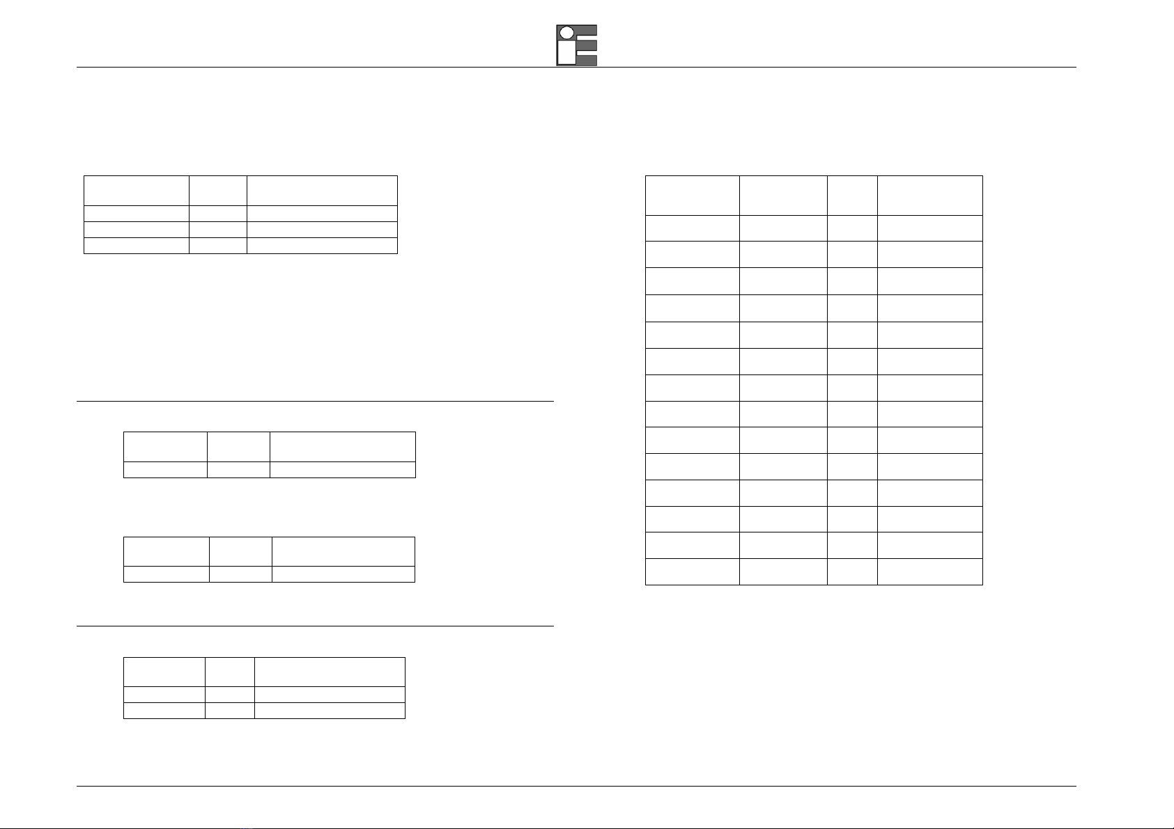
2.2.3 MicroCal P20 codes
Cat. 3240 basic AA - B - C - D
Standard packaging includes: MicroCal P20 basic calibrator (2 internal sensors + external sensor pressure connector), battery charger, instruction manual, and Eurotron Report of calibration.
Cat. 3240 plus AA - B - C - D
Standard packaging includes: MicroCal P20 plus calibrator (2 internal sensors + external sensor pressure connector + mA/V/Pt100 input/output), battery charger, instruction manual, and Eurotron Report
of calibration.
Intrinsic Safety (IS) Model:
Cat. 3241 IS plus AA - B - C - D
Standard packaging includes: MicroCal P20 IS plus calibrator (2 internal sensor + external sensors pressure connector + mA/V/Pt100 input/output), battery charger, instruction manual, and Eurotron
Report of calibration.
Table A Internal pressure sensor ±0.025% FS
0 None
2 -100 to 100 mbar Gauge res. 0.001mbar
3 -500 to 500 mbar Gauge res. 0.01mbar
4 -0.95 to 1 bar Gauge res. 0.01mbar
5 -0.95 to 2 bar Gauge res. 0.01mbar
5A 2 bar Absolute res. 0.01mbar
6 -0.95 to 7 bar Gauge res. 0.1mbar
7 -0.95 to 20 bar Gauge res. 0.1mbar
7A 20 bar Absolute res. 0.1mbar
Table B Line charger
1 120V 50/60Hz with USA plug
2 230V 50/60Hz with Schuko plug
3 230V 50/60Hz with UK plug
4 230V 50/60Hz with European plug
5 100V 50/60Hz with USA/Japan plug
Table C Options
0 None
1 HART protocol
2 EC module (T+RH%+Barometric internal sensors), not available on ATEX models
Table D Calibration certificate
1 Eurotron report

Instruction Manual MM850432 ed. 05
11
2.3 Accessories
EXTERNAL PRESSURE MODULES - AISI 316SS - ±0.025% F.S.
GAUGE
BB480009 from -100 to 100 mbar (1.5 PSI) res. 0.001mbar
BB480010 from -500 to 500 mbar (7 PSI) res. 0.01mbar
BB480011 from -0.95 to 1 bar (15 PSI) res. 0.01mbar
BB480012 from -0.95 to 2 bar (30 PSI) res. 0.01mbar
BB480013 from -0.95 to 7bar (100 PSI) res. 0.1mbar
BB480014 from -0.95 to 20 bar (300 PSI) res. 0.1mbar
BB480015 from -0.95 to 35 bar (500 PSI) res. 1mbar
BB480016 from 0 to 70 bar (1000 PSI) res. 1mbar
BB480017 from 0 to 150 bar (2000 PSI) res. 1mbar
BB480018 from 0 to 350 bar (5000 PSI) res. 10mbar
BB480019 from 0 to 700 bar (10000 PSI) res. 10mbar
ABSOLUTE
BB480020 from 0 to 2 bar (30 PSI) res. 0.01mbar
BB480021 from 0 to 20 bar (300 PSI) res. 0.1mbar
HAND PUMPS
F3280013 External pneumatic hand pump –0.8 to 2 bar
F3280002 External pneumatic hand pump –0.8 to 20 bar
F3280010 External pneumatic hand pump –0.95 to 40 bar
F3280015 External Hydraulic hand pump 700 bar
F3280016 External Hydraulic hand pump 1000 bar
SOFTWARE
BB530203 RS232 adapter cable
BB530212 USB cable
BB260198 LogMan
BB260199 LinMan
BB260215 CalpMan 2007
BB260130 CalpMan 2007 Advanced
BB530204 MicroCal T series communication module
MISCELLANEOUS
EE300040 Electrical signal test lead kit
BB300122 Tc cable connection kit
BB880043 Vinyl protection carrying case with shoulder strap
BB880048 ABS carrying case
BB880033 Aluminium carrying case
BB880049 Rubber holster with shoulder strap
Instruction Manual MM850432 ed. 05c
12
2.4 Technical specifications
2.4.1 MicroCal 20 DPC
NOTE: FOR THE IS MODELS SEE CHAPTER.15
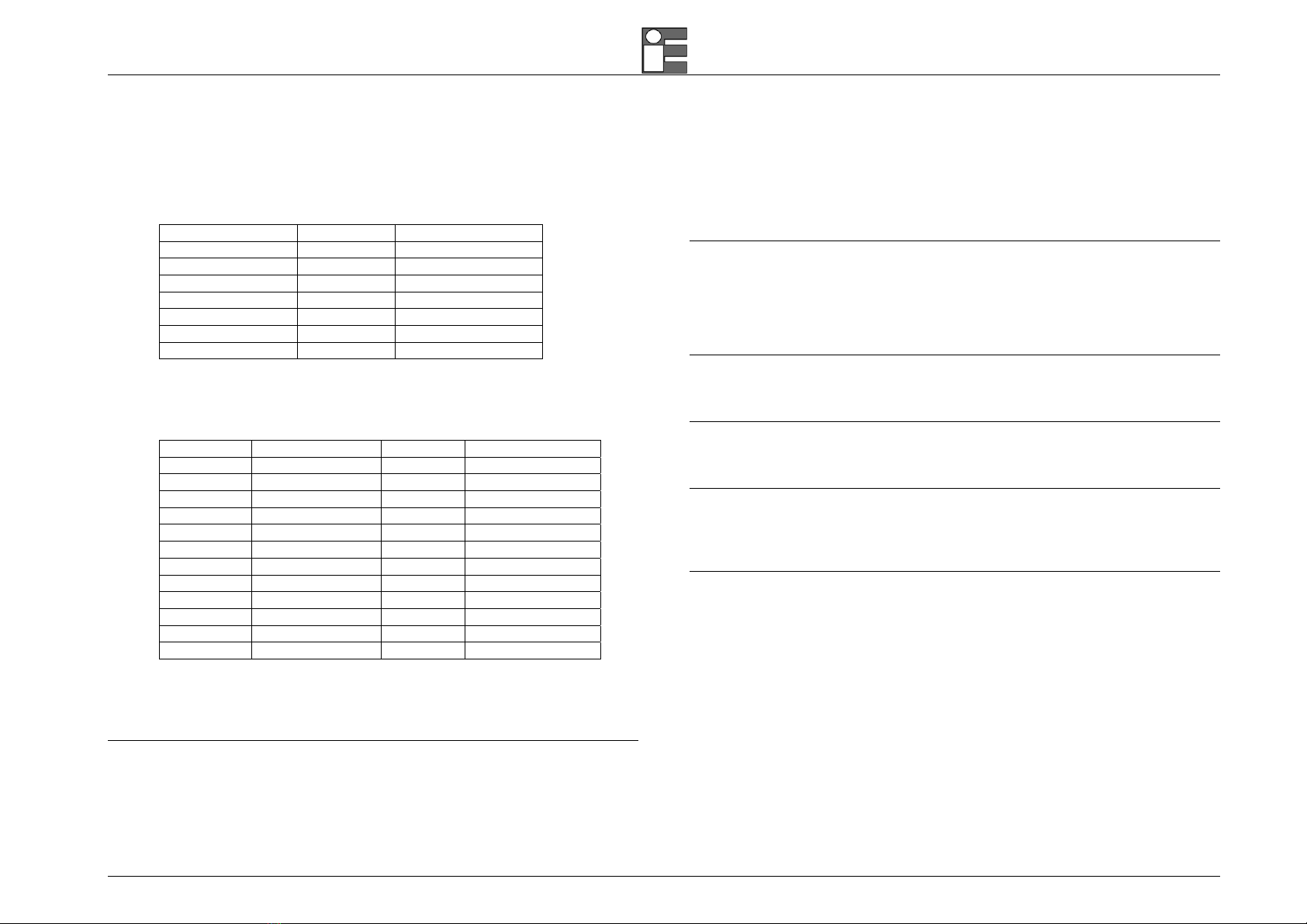
IN/OUT Voltage
RANGE RES. ACCURACY
BASIC model
-20 to 200 mV 1 µV ±(0.02% rdg + 3 µV)
-0.2 to 2 V 10 µV ±(0.02% rdg + 10 µV)
-2 to 20 V 100 µV ±(0.02% rdg + 0.1 mV)
RANGE RES. ACCURACY
Plus model ACCURACY
XP model
-20 to 200 mV 1 µV ±(0.01% rdg + 3 µV) ±(0.006% rdg + 3 µV)
-0.2 to 2 V 10 µV ±(0.01% rdg + 10 µV) ±(0.006% rdg + 10 µV)
-2 to 20 V 100 µV ±(0.01% rdg + 0.1 mV) ±(0.01% rdg + 0.1 mV)
Input impedance:
>10 MΩfor ranges up to 2000 mV f.s.
>500 kΩfor ranges up to 20 V f.s.
Output impedance (emf output): less than 0.5 Ωwith a maximum current of 0.5 mA
Output noise (at 300 Hz):
<2 µVpp for ranges up to 200 mV f.s.,
<10 µVpp for ranges up to 2000 mV f.s.
<80 µVpp for ranges up to 20 V f.s.
IN/OUT Current
Input mode
RANGE RES. ACCURACY
Plus / XP models ACCURACY
BASIC model
-5 to 50 mA 0.1 µA ±(0.01% rdg + 0.4 µA) ±(0.02% rdg + 0.4 µA)
Input impedance: <20 Ωat 1 mA
Output mode
RANGE RES. ACCURACY
Plus / XP models ACCURACY
BASIC model
0 to 50 mA 0.1 µA ±(0.01% rdg + 0.4 µA) ±(0.02% rdg + 0.4 µA)
Notes: limited to 21 mA max on passive current loop (the Microcal supply
the Tag).
IS model channel 2 source Max 11 V.
IN/OUT Resistance and RTDs
Resistance input mode
RANGE RES. ACCURACY
BASIC model
0 to 500 Ω1 mΩ±(0.02% rdg + 12 mΩ)
0 to 5000 Ω10 mΩ±(0.02% rdg + 120 mΩ)
RANGE RES. ACCURACY
Plus model ACCURACY
XP model
0 to 500 Ω1 mΩ±(0.008% rdg + 12 mΩ) ±(0.01% rdg + 12 mΩ)
0 to 5000 Ω10 mΩ±(0.008% rdg + 120 mΩ) ±(0.01% rdg + 120 mΩ)
Resistance output mode
RANGE RES. ACCURACY
BASIC model
0 to 500 Ω1 mΩ±(0.02% rdg + 20 mΩ)
0 to 5000 Ω10 mΩ±(0.02% rdg + 200 mΩ)
RANGE RES. ACCURACY
Plus model ACCURACY
XP model
0 to 500 Ω1 mΩ±(0.008% rdg + 20 mΩ) ±(0.01% rdg + 20 mΩ)
0 to 5000 Ω10 mΩ±(0.008% rdg + 200 mΩ) ±(0.01% rdg + 200 mΩ)
Note: IS model channel 2 source Max 11 V.
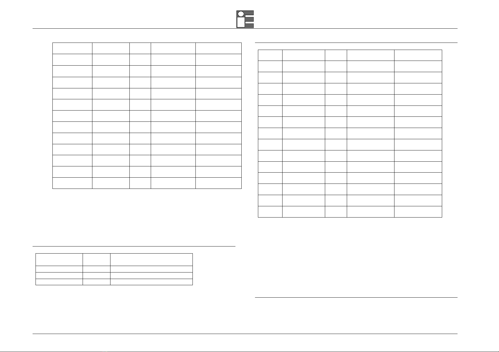
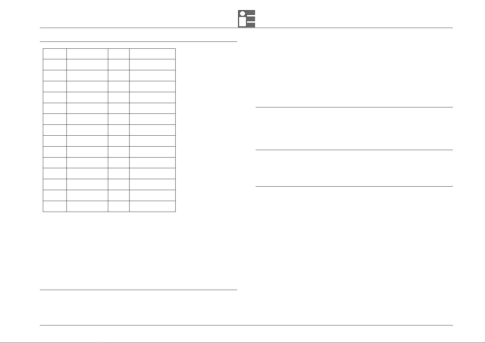
RTDs IN/OUT mode
RTD TYPE RANGE RES. ACCURACY
Plus / XP models
(% rdg)
ACCURACY
BASIC models
(% rdg)
Pt100
IEC
-200 / 850°C
-330 / 1570°F
0.01 °C
0.01 °F
±(0.01% +0.05°C)
±(0.01% +0.09°F) ±(0.02% +0.05°C)
±(0.02% +0.09°F)
Instruction Manual MM850432 ed. 05
13
Pt100
OIML
-200 / 850°C
-330 / 1570°F
0.01 °C
0.01 °F
±(0.01% +0.05°C)
±(0.01% +0.09°F) ±(0.02% +0.05°C)
±(0.02% +0.09°F)
Pt100
α=.3926
-200 / 850°C
-330 / 1570°F
0.01 °C
0.01 °F
±(0.01% +0.05°C)
±(0.01% +0.09°F) ±(0.02% +0.05°C)
±(0.02% +0.09°F)
Pt100
α=.3902
-200 / 650°C
-330 / 1210°F
0.01 °C
0.01 °F
±(0.01% +0.05°C)
±(0.01% +0.09°F) ±(0.02% +0.05°C)
±(0.02% +0.09°F)
Pt100
JIS
-200 / 600°C
-330 / 1120°F
0.01 °C
0.01 °F
±(0.01% +0.05°C)
±(0.01% +0.09°F) ±(0.02% +0.05°C)
±(0.02% +0.09°F)
Pt100
SAMA
-200 / 600°C
-330 / 1120°F
0.01 °C
0.01 °F
±(0.01% +0.05°C)
±(0.01% +0.09°F) ±(0.02% +0.05°C)
±(0.02% +0.09°F)
Pt200 -200 / 850°C
-330 / 1570°F
0.1 °C
0.1 °F
±(0.01% +0.15°C)
±(0.01% +0.27°F) ±(0.02% +0.15°C)
±(0.02% +0.27°F)
Pt500 -200 / 850°C
-330 / 1570°F
0.1 °C
0.1 °F
±(0.01% +0.1°C)
±(0.01% +0.2°F) ±(0.02% +0.1°C)
±(0.02% +0.2°F)
Pt1000
IEC
-200 / 850°C
-330 / 1570°F
0.1 °C
0.1 °F
±(0.01% +0.1°C)
±(0.01% +0.2°F) ±(0.02% +0.1°C)
±(0.02% +0.2°F)
Pt1000
OIML
-200 / 850°C
-330 / 1570°F
0.1 °C
0.1 °F
±(0.01% +0.1°C)
±(0.01% +0.2°F) ±(0.02% +0.1°C)
±(0.02% +0.2°F)
Cu10 -70 / 150°C
-100 / 310°F
0.1 °C
0.1 °F
±(0.01% +0.4°C)
±(0.01% +0.7°F) ±(0.02% +0.4°C)
±(0.02% +0.7°F)
Cu100 -180 / 150°C
-300 / 310°F
0.1 °C
0.1 °F
±(0.01% +0.05°C)
±(0.01% +0.09°F) ±(0.02% +0.05°C)
±(0.02% +0.09°F)
Ni100 -60 / 180°C
-80 / 360°F
0.1 °C
0.1 °F
±(0.01% +0.05°C)
±(0.01% +0.09°F) ±(0.02% +0.05°C)
±(0.02% +0.09°F)
Ni120 -0 / 150°C
32 / 310°F
0.1 °C
0.1 °F
±(0.01% +0.05°C)
±(0.01% +0.09°F) ±(0.02% +0.05°C)
±(0.02% +0.09°F)
Connections: 2, 3 and 4 wires
Source resistance effects: ±1 µV error for 1000Ωsource resistance
Rtd and Ωsimulation excitation current: from 0.100 to 2 mA without incremental error
Rtd and Ωmeasurement excitation current: 0.2 mA
Rtd cable compensation: up to 100 m Ω (for each wire)
Rtd cable compensation error (Pt100): ±0.005°C/ Ωof total wire
Maximum load resistance: 1000 Ωat 20 mA
IN Frequency/Pulse
RANGE RESOL. ACCURACY
BASIC / Plus / XP models
1 to 200 Hz 0.001 Hz ±(0.005% rdg + 0.001 Hz)
1 to 2000 Hz 0.01 Hz ±(0.005% rdg + 0.01 Hz)
1 to 20000 Hz 0.1 Hz ±(0.005% rdg + 0.1 Hz)
Input impedance:
IN/OUT Thermocouples
TC TYPE RANGE RESOL. ACCURACY
Plus / XP models ACCURACY
BASIC model
Tc J -210 to 1200 °C
-35 to 2200 °F
0.01 °C
0.01 °F
±(0.01% +0.1°C)
±(0.01% +0.2°F) ±(0.02% +0.1°C)
±(0.02% +0.2°F)
Tc K -270 to 1370 °C
-450 to 2500 °F
0.01 °C
0.01 °F
±(0.01% +0.1°C)
±(0.01% +0.2°F) ±(0.02% +0.1°C)
±(0.02% +0.2°F)
Tc T -270 to 400 °C
-450 to 760 °F
0.01 °C
0.01 °F
±(0.01% +0.1°C)
±(0.01% +0.2°F) ±(0.02% +0.1°C)
±(0.02% +0.2°F)
Tc R -50 to 1760 °C
-60 to 3200 °F
0.1 °C
0.1 °F
±(0.01% +0.2°C)
±(0.01% +0.4°F) ±(0.02% +0.2°C)
±(0.02% +0.4°F)
Tc S -50 to 1760 °C
-60 to 3200 °F
0.1 °C
0.1 °F
±(0.01% +0.2°C)
±(0.01% +0.4°F) ±(0.02% +0.2°C)
±(0.02% +0.4°F)
Tc B 50 to 1820 °C
140 to 3300 °F
0.1 °C
0.1 °F
±(0.01% +0.3°C)
±(0.01% +0.6°F) ±(0.02% +0.3°C)
±(0.02% +0.6°F)
Tc C 0 to 2300 °C
32 to 4150 °F
0.1 °C
0.1 °F
±(0.01% +0.2°C)
±(0.01% +0.4°F) ±(0.02% +0.2°C)
±(0.02% +0.4°F)
Tc G 0 to 2300 °C
32 to 4150 °F
0.1 °C
0.1 °F
±(0.01% +0.3°C)
±(0.01% +0.6°F) ±(0.02% +0.3°C)
±(0.02% +0.6°F)
Tc D 0 to 2300 °C
32 to 4150 °F
0.1 °C
0.1 °F
±(0.01% +0.3°C)
±(0.01% +0.6°F) ±(0.02% +0.3°C)
±(0.02% +0.6°F)
Tc U -200 to 400 °C
-330 to 760 °F
0.1 °C
0.1 °F
±(0.01% +0.1°C)
±(0.01% +0.2°F) ±(0.02% +0.1°C)
±(0.02% +0.2°F)
Tc L -200 to 760 °C
-330 to 1400 °F
0.1 °C
0.1 °F
±(0.01% +0.1°C)
±(0.01% +0.2°F) ±(0.02% +0.1°C)
±(0.02% +0.2°F)
Tc N -270 to 1300 °C
-450 to 2380 °F
0.1 °C
0.1 °F
±(0.01% +0.1°C)
±(0.01% +0.2°F) ±(0.02% +0.1°C)
±(0.02% +0.2°F)
Tc E -270 to 1000 °C
-450 to 1840 °F
0.1 °C
0.1 °F
±(0.01% +0.1°C)
±(0.01% +0.2°F) ±(0.02% +0.1°C)
±(0.02% +0.2°F)
Tc F 0 to 1400 °C
32 to 2560 °F
0.1 °C
0.1 °F
±(0.01% +0.1°C)
±(0.01% +0.2°F) ±(0.02% +0.1°C)
±(0.02% +0.2°F)
Note: 0.1°C resolution with temperature lower than –200°C
Selection °C/°F/K: through the configuration procedure
Resolution: 0.01°C / 0.01°F
Temperature scale: ITS90 and IPTS68 selectable
Reference junction compensation:
internal automatic from -10 °C to +55 °C
external adjustable from -50 °C to +100 °C
remote with external Pt100 from -10°C to +100 °C (only on XP model)
Rj compensation drift: ± 0.002°C/°C (from -10 °C to +45 °C)
Rj accuracy: ±0.05°C @ 25°C / ±0.005 °C/°C
Input impedance (Tc ranges): >10 MΩ
Pressure (option)
Pressure media: AISI 316 SS compatible fluids (water, gas, and oil)
Instruction Manual MM850432 ed. 05c
14
Temperature compensation: Automatic with built-in calibration matrix from 0°C to
50°C.
Engineering units: mbar, bar, Pa, hPa, kPa, MPa, kg/cm2, kg/m2, psi, mmH2O,
cmH2O, mH2O, Torr, atm, lb/ft2, inH2O, ftH2O, inH2O@4°C, ftH2O@4°C, mmHg,
cmHg, mHg, inHg, programmable.
Internal sensors
RANGE RESOL. ACCURACY
-100 to 100 mbar 0.001mbar ±0.025 % F.S.
-500 to 500 mbar 0. 01mbar ±0. 025 % F.S.
-0.95 to 2 bar 0.01mbar ±0. 025 % F.S.
0 to 2 bar (ABS) 0.01mbar ±0. 025 % F.S.
-0. 95 to 7 bar 0.1mbar ±0. 025 % F.S.
-0. 95 to 20 bar 0.1mbar ±0. 025 % F.S.
0 to 20 bar (ABS) 0.1mbar ±0. 025 % F.S.
Overpressure: 125% F.S.
Port: 1/8 BSPF (female)
External sensors
PART No. RANGE RESOL. ACCURACY
BB480009 -100 to 100 mbar 0.001 mbar ±0. 025 % F.S.
BB480010 -500 to 500 mbar 0. 01 mbar ±0. 025 % F.S.
BB480012 -0.95 to 2 bar 0.01 mbar ±0. 025 % F.S.
BB480020 0 to 2 bar (ABS) 0.01 mbar ±0. 025 % F.S.
BB480013 -0. 95 to 7 bar 0.1 mbar ±0. 025 % F.S.
BB480014 -0. 95 to 20 bar 0.1 mbar ±0. 025 % F.S.
BB480021 0 to 20 bar (ABS) 0.1 mbar ±0. 025 % F.S.
BB480015 -0. 95 to 35 bar 1 mbar ±0. 025 % F.S.
BB480016 0 to 70 bar 1 mbar ±0. 025 % F.S.
BB480017 0 to 150 bar 1 mbar ±0. 025 % F.S.
BB480018 0 to 350 bar 10 mbar ±0. 025 % F.S.
BB480019 0 to 700 bar 10 mbar ±0. 025 % F.S.
Overpressure: 125% F.S.
Port: ¼ BSPM (male)
Connection wire length: 2 meters
Environmental condition module (option) - Not available on IS models
Temperature:
Sensor type: Pt100
Range:
Accuracy:
Relative Humidity:
Sensor type:
Range: 0 to 95% RH
Accuracy: ±2% RH
Pressure:
Sensor type:
Range:
Accuracy: ±2 mbar
Math functions
Calculation functions: hold, max, min, offset, zero, average
In/Out data memory: 10 data with manual or automatic recall
Convert function: displays the electrical equivalent of the engineering unit
Scale factor: setting with zero and span programmable
Square root: in combination with scale factor
Transmitter
Sources: Voltage, current, Temperature, Resistance
Response time: 0.1 / 1 / 10 sec selectable
Ramp / Cycle
Sources: Voltage, Current, Temperature, Resistance
Sampling time: MAX. 0.1 sec
DataLogger
Sources: Voltage, Current, Temperature, Resistance
Sampling time: MAX. 1 sec
Memory: >1500 readings complete with date and time
General
Accuracy: the above accuracies are stated for 365 days and includes non-linearity,
hysteresis, and repeatability. The average temperature coefficient, inside the
temperature compensated range is ±0.002 of rdg/°C (w.t.r. +23°C / +73°F).
Compensation temperature range: 0 to 45°C (+32 to +113°F)
Calibration: self learning technique with automatic procedure
Channel 1-Channel 2 insulation: 250 Vdc
Common mode rejection: 140 dB at ac operation
Normal mode rejection: 60 dB at 50/60 Hz
Temperature stability: for temperature exceeding the band +18°C to 28°C
Span: ±8 ppm/°C
Zero: ±0.2 µV/°C
Measurement sampling time: 250 ms
Display: graphic LCD display with automatic and manual backlight device
Digital interface: full bi-directional RS232
Internal data memory: standard 512 kb – Optional 8Mb with internal card

Instruction Manual MM850432 ed. 05
15
Power supply: external charger and rechargeable Ni-MH battery
Battery life (typical):
10 h (8 h on IS models) on Tc and mV input/output (backlight Off)
4 h (3 h on IS models) with 20 mA simulation (backlight Off)
Recharging time (typical): 5 h (8 h on IS models) at 90% and 6 h (10 h on IS models)
at 99% with instrument switched off.
Battery charge indication: bar graph on the LCD display (flashing on charge)
Line operation: 100V - 120 V - 230V - 240 Vac with the external battery charger
Line transformer insulation: 2500 Vac
Sealing: IP54
Operating environment temperature range: from -10 °C to +55 °C
Storage temperature range: from 0 °C to +60 °C (excluding batteries)
Humidity: max 95%RH non condensing
Case: Injection moulded polycarbonate case
Weights: net 1.4 Kg gross 2.5 Kg
Dimensions: 290x98x57 mm
Warranty: 2 Years.
Instruction Manual MM850432 ed. 05c
16
2.4.2 MicroCal P20
NOTE: FOR THE IS MODEL SEE CHAPTER 15
IN/OUT Voltage
RANGE RES. ACCURACY
Plus model
-20 to 200 mV 1 µV ±(0.01% rdg + 3 µV)
-0.2 to 2 V 10 µV ±(0.01% rdg + 10 µV)
-2 to 20 V 100 µV ±(0.01% rdg + 0.1 mV)
Input impedance:
>10 MΩfor ranges up to 2000 mV f.s.
>500 kΩfor ranges up to 20 V f.s.
Output impedance (emf output): less than 0.5 Ωwith a maximum current of 0.5 mA
Output noise (at 300 Hz):
<2 µVpp for ranges up to 200 mV f.s.,
<10 µVpp for ranges up to 2000 mV f.s.
<80 µVpp for ranges up to 20 V f.s.
IN/OUT Current
Input mode
RANGE RES. ACCURACY
Plus model
-5 to 50 mA 0.1 µA ±(0.01% rdg + 0.4 µA)
Input impedance: <20 Ωat 1 mA
Output mode
RANGE RES. ACCURACY
Plus model
0 to 50 mA 0.1 µA ±(0.01% rdg + 0.4 µA)
Notes: limited to 21 mA max on passive current loop (the Microcal supply
the Tag).
IS model channel 2 source Max 11 V.
IN Resistance and RTDs
Resistance input mode
RANGE RES. ACCURACY
Plus model
0 to 500 Ω1 mΩ±(0.01% rdg + 12 mΩ)
0 to 5000 Ω10 mΩ±(0.01% rdg + 120 mΩ)
RTDs IN mode
RTD TYPE RANGE RES. ACCURACY
Plus model
(% rdg)
Pt100
IEC
-200 / 850°C
-330 / 1570°F
0.01 °C
0.01 °F
±(0.01% +0.05°C)
±(0.01% +0.09°F)
Pt100
OIML
-200 / 850°C
-330 / 1570°F
0.01 °C
0.01 °F
±(0.01% +0.05°C)
±(0.01% +0.09°F)
Pt100
α=.3926
-200 / 850°C
-330 / 1570°F
0.01 °C
0.01 °F
±(0.01% +0.05°C)
±(0.01% +0.09°F)
Pt100
α=.3902
-200 / 650°C
-330 / 1210°F
0.01 °C
0.01 °F
±(0.01% +0.05°C)
±(0.01% +0.09°F)
Pt100
JIS
-200 / 600°C
-330 / 1120°F
0.01 °C
0.01 °F
±(0.01% +0.05°C)
±(0.01% +0.09°F)
Pt100
SAMA
-200 / 600°C
-330 / 1120°F
0.01 °C
0.01 °F
±(0.01% +0.05°C)
±(0.01% +0.09°F)
Pt200 -200 / 850°C
-330 / 1570°F
0.1 °C
0.1 °F
±(0.01% +0.15°C)
±(0.01% +0.27°F)
Pt500 -200 / 850°C
-330 / 1570°F
0.1 °C
0.1 °F
±(0.01% +0.1°C)
±(0.01% +0.2°F)
Pt1000
IEC
-200 / 850°C
-330 / 1570°F
0.1 °C
0.1 °F
±(0.01% +0.1°C)
±(0.01% +0.2°F)
Pt1000
OIML
-200 / 850°C
-330 / 1570°F
0.1 °C
0.1 °F
±(0.01% +0.1°C)
±(0.01% +0.2°F)
Cu10 -70 / 150°C
-100 / 310°F
0.1 °C
0.1 °F
±(0.01% +0.4°C)
±(0.01% +0.7°F)
Cu100 -180 / 150°C
-300 / 310°F
0.1 °C
0.1 °F
±(0.01% +0.05°C)
±(0.01% +0.09°F)
Ni100 -60 / 180°C
-80 / 360°F
0.1 °C
0.1 °F
±(0.01% +0.05°C)
±(0.01% +0.09°F)
Ni120 -0 / 150°C
32 / 310°F
0.1 °C
0.1 °F
±(0.01% +0.05°C)
±(0.01% +0.09°F)
Connections: 2, 3 and 4 wires
Source resistance effects: ±1 µV error for 1000Ωsource resistance
Rtd and Ωsimulation excitation current: from 0.100 to 2 mA without incremental error
Rtd and Ωmeasurement excitation current: 0.2 mA
Rtd cable compensation: up to 100 m Ω (for each wire)
Rtd cable compensation error (Pt100): ±0.005°C/ Ωof total wire
Maximum load resistance: 1000 Ωat 20 mA

Instruction Manual MM850432 ed. 05
17
IN Frequency/Pulse
RANGE RESOL. ACCURACY
Plus model
1 to 200 Hz 0.001 Hz ±(0.005% rdg + 0.001 Hz)
1 to 2000 Hz 0.01 Hz ±(0.005% rdg + 0.01 Hz)
1 to 20000 Hz 0.1 Hz ±(0.005% rdg + 0.1 Hz)
Input impedance:
Pressure (option)
Pressure media: AISI 316 SS compatible fluids (water, gas, and oil)
Temperature compensation: Automatic with built-in calibration matrix.
Engineering units: mbar, bar, Pa, hPa, kPa, MPa, kg/cm2, kg/m2, psi, mmH2O,
cmH2O, mH2O, Torr, atm, lb/ft2, inH2O, ftH2O, inH2O@4°C, ftH2O@4°C, mmHg,
cmHg, mHg, inHg, programmable.
Internal sensors
RANGE RESOL. ACCURACY
-100 to 100 mbar 0.001mbar ±0.25 % F.S.
-500 to 500 mbar 0. 01mbar ±0.25 % F.S.
-0.95 to 2 bar 0.01mbar ±0.25 % F.S.
0 to 2 bar (ABS) 0.01mbar ±0.25 % F.S.
-0. 95 to 7 bar 0.1mbar ±0.25 % F.S.
-0. 95 to 20 bar 0.1mbar ±0.25 % F.S.
0 to 20 bar (ABS) 0.1mbar ±0.25 % F.S.
Overpressure: 125% F.S.
Port: 1/8 BSPF (female)
External sensors
PART No. RANGE RESOL. ACCURACY
BB480009 -100 to 100 mbar 0.001 mbar ±0.25 % F.S.
BB480010 -500 to 500 mbar 0. 01 mbar ±0.25 % F.S.
BB480012 -0.95 to 2 bar 0.01 mbar ±0.25 % F.S.
BB480020 0 to 2 bar (ABS) 0.01 mbar ±0.25 % F.S.
BB480013 -0. 95 to 7 bar 0.1 mbar ±0.25 % F.S.
BB480014 -0. 95 to 20 bar 0.1 mbar ±0.25 % F.S.
BB480021 0 to 20 bar (ABS) 0.1 mbar ±0.25 % F.S.
BB480015 -0. 95 to 35 bar 1 mbar ±0.25 % F.S.
BB480016 0 to 70 bar 1 mbar ±0.25 % F.S.
BB480017 0 to 150 bar 1 mbar ±0.25 % F.S.
BB480018 0 to 350 bar 10 mbar ±0.25 % F.S.
BB480019 0 to 700 bar 10 mbar ±0.25 % F.S.
Overpressure: 125% F.S.
Port: ¼ BSPM (male)
Connection wire length: 2 meters
Environmental condition module (option) - Not available on IS models
Temperature:
Sensor type: Pt100
Range:
Accuracy:
Relative Humidity:
Sensor type:
Range: 0 to 95% RH
Accuracy: ±2% RH
Pressure:
Sensor type:
Range:
Accuracy: ±2 mbar
Math functions
Calculation functions: hold, max, min, offset, zero, average
In/Out data memory: 10 data with manual or automatic recall
Convert function: displays the electrical equivalent of the engineering unit
Scale factor: setting with zero and span programmable
Square root: in combination with scale factor
DataLogger
Sources: Voltage, Current, Temperature, Resistance
Sampling time: 1 sec
Memory: >1500 readings complete with date and time
General
Accuracy: the above accuracies are stated for 365 days and includes non-linearity,
hysteresis, and repeatability. The average temperature coefficient, inside the
temperature compensated range is ±0.002 of rdg/°C (w.t.r. +23°C / +73°F).
Compensation temperature range: 0 to 45°C (+32 to +113°F)
Calibration: self learning technique with automatic procedure
Common mode rejection: 140 dB at ac operation
Normal mode rejection: 60 dB at 50/60 Hz
Temperature stability: for temperature exceeding the band +18°C to 28°C
Span: ±8 ppm/°C
Zero: ±0.2 µV/°C

Instruction Manual MM850432 ed. 05c
18
Measurement sampling time: 250 ms
Display: graphic LCD display with automatic and manual backlight device
Digital interface: full bi-directional RS232
Power supply: external charger and rechargeable Ni-MH battery
Battery life (typical):
10 h (8 h on IS models) on Tc and mV input/output (backlight Off)
4 h (4 h on IS models) with 20 mA simulation (backlight Off)
Recharging time (typical): 5 h (8 h on IS models) at 90% and 6 h (10 h on IS models)
at 99% with instrument switched off.
Battery charge indication: bar graph on the LCD display (flashing on charge)
Line operation: 100V - 120 V - 230V - 240 Vac with the external battery charger
Line transformer insulation: 2500 Vac
Sealing: IP54
Operating environment temperature range: from -10 °C to +55 °C
Storage temperature range: from 0 °C to +60 °C (excluding batteries)
Humidity: max 95%RH non condensing
Case: Injection moulded polycarbonate case
Weights: net 1.4 Kg gross 2.5 Kg
Dimensions: 290x98x57 mm
Warranty: 2 Years.
Instruction Manual MM850432 ed. 05
19
2.4.3 MicroCal 20T
IN Voltage
RANGE RES. ACCURACY
-20 to 200 mV 1 µV ±(0.01% rdg + 3 µV)
-0.2 to 2 V 10 µV ±(0.01% rdg + 10 µV)
-2 to 20 V 100 µV ±(0.01% rdg + 0.1 mV)
Input impedance:
>10 MΩfor ranges up to 2000 mV f.s.
>500 kΩfor ranges up to 20 V f.s.
Output impedance (emf output): less than 0.5 Ωwith a maximum current of 0.5 mA
Output noise (at 300 Hz):
<2 µVpp for ranges up to 200 mV f.s.,
<10 µVpp for ranges up to 2000 mV f.s.
<80 µVpp for ranges up to 20 V f.s.
IN Current
Input mode
RANGE RES. ACCURACY
-5 to 50 mA 0.1 µA ±(0.01% rdg + 0.4 µA)
Input impedance: <20 Ωat 1 mA
Output mode
RANGE RES. ACCURACY
0 to 50 mA 0.1 µA ±(0.01% rdg + 0.4 µA)
Note: limited to 21 mA max on passive current loop (the Microcal supply the
Tag).
IN Resistance and RTDs
Resistance input mode
RANGE RES. ACCURACY
0 to 500 Ω1 mΩ±(0.01% rdg + 12 mΩ)
0 to 5000 Ω10 mΩ±(0.01% rdg + 120 mΩ)
RTDs IN mode
RTD TYPE RANGE RES. ACCURACY
Plus model
(% rdg)
Pt100
IEC
-200 / 850°C
-330 / 1570°F
0.01 °C
0.01 °F
±(0.01% +0.05°C)
±(0.01% +0.09°F)
Pt100
OIML
-200 / 850°C
-330 / 1570°F
0.01 °C
0.01 °F
±(0.01% +0.05°C)
±(0.01% +0.09°F)
Pt100
α=.3926
-200 / 850°C
-330 / 1570°F
0.01 °C
0.01 °F
±(0.01% +0.05°C)
±(0.01% +0.09°F)
Pt100
α=.3902
-200 / 650°C
-330 / 1210°F
0.01 °C
0.01 °F
±(0.01% +0.05°C)
±(0.01% +0.09°F)
Pt100
JIS
-200 / 600°C
-330 / 1120°F
0.01 °C
0.01 °F
±(0.01% +0.05°C)
±(0.01% +0.09°F)
Pt100
SAMA
-200 / 600°C
-330 / 1120°F
0.01 °C
0.01 °F
±(0.01% +0.05°C)
±(0.01% +0.09°F)
Pt200 -200 / 850°C
-330 / 1570°F
0.1 °C
0.1 °F
±(0.01% +0.15°C)
±(0.01% +0.27°F)
Pt500 -200 / 850°C
-330 / 1570°F
0.1 °C
0.1 °F
±(0.01% +0.1°C)
±(0.01% +0.2°F)
Pt1000
IEC
-200 / 850°C
-330 / 1570°F
0.1 °C
0.1 °F
±(0.01% +0.1°C)
±(0.01% +0.2°F)
Pt1000
OIML
-200 / 850°C
-330 / 1570°F
0.1 °C
0.1 °F
±(0.01% +0.1°C)
±(0.01% +0.2°F)
Cu10 -70 / 150°C
-100 / 310°F
0.1 °C
0.1 °F
±(0.01% +0.4°C)
±(0.01% +0.7°F)
Cu100 -180 / 150°C
-300 / 310°F
0.1 °C
0.1 °F
±(0.01% +0.05°C)
±(0.01% +0.09°F)
Ni100 -60 / 180°C
-80 / 360°F
0.1 °C
0.1 °F
±(0.01% +0.05°C)
±(0.01% +0.09°F)
Ni120 -0 / 150°C
32 / 310°F
0.1 °C
0.1 °F
±(0.01% +0.05°C)
±(0.01% +0.09°F)
Connections: 2, 3 and 4 wires
Source resistance effects: ±1 µV error for 1000Ωsource resistance
Rtd and Ωsimulation excitation current: from 0.100 to 2 mA without incremental error
Rtd and Ωmeasurement excitation current: 0.2 mA
Rtd cable compensation: up to 100 m Ω (for each wire)
Rtd cable compensation error (Pt100): ±0.005°C/ Ωof total wire
Maximum load resistance: 1000 Ωat 20 mA
Instruction Manual MM850432 ed. 05c
20
IN Thermocouples
TC TYPE RANGE RESOL. ACCURACY
Plus model
Tc J -210 to 1200 °C
-35 to 2200 °F
0.01 °C
0.01 °F
±(0.01% +0.1°C)
±(0.01% +0.2°F)
Tc K -270 to 1370 °C
-450 to 2500 °F
0.01 °C
0.01 °F
±(0.01% +0.1°C)
±(0.01% +0.2°F)
Tc T -270 to 400 °C
-450 to 760 °F
0.01 °C
0.01 °F
±(0.01% +0.1°C)
±(0.01% +0.2°F)
Tc R -50 to 1760 °C
-60 to 3200 °F
0.1 °C
0.1 °F
±(0.01% +0.2°C)
±(0.01% +0.4°F)
Tc S -50 to 1760 °C
-60 to 3200 °F
0.1 °C
0.1 °F
±(0.01% +0.2°C)
±(0.01% +0.4°F)
Tc B 50 to 1820 °C
140 to 3300 °F
0.1 °C
0.1 °F
±(0.01% +0.3°C)
±(0.01% +0.6°F)
Tc C 0 to 2300 °C
32 to 4150 °F
0.1 °C
0.1 °F
±(0.01% +0.2°C)
±(0.01% +0.4°F)
Tc G 0 to 2300 °C
32 to 4150 °F
0.1 °C
0.1 °F
±(0.01% +0.3°C)
±(0.01% +0.6°F)
Tc D 0 to 2300 °C
32 to 4150 °F
0.1 °C
0.1 °F
±(0.01% +0.3°C)
±(0.01% +0.6°F)
Tc U -200 to 400 °C
-330 to 760 °F
0.1 °C
0.1 °F
±(0.01% +0.1°C)
±(0.01% +0.2°F)
Tc L -200 to 760 °C
-330 to 1400 °F
0.1 °C
0.1 °F
±(0.01% +0.1°C)
±(0.01% +0.2°F)
Tc N -270 to 1300 °C
-450 to 2380 °F
0.1 °C
0.1 °F
±(0.01% +0.1°C)
±(0.01% +0.2°F)
Tc E -270 to 1000 °C
-450 to 1840 °F
0.1 °C
0.1 °F
±(0.01% +0.1°C)
±(0.01% +0.2°F)
Tc F 0 to 1400 °C
32 to 2560 °F
0.1 °C
0.1 °F
±(0.01% +0.1°C)
±(0.01% +0.2°F)
Note: 0.1°C resolution with temperature lower than –200°C
Selection °C/°F/K: through the configuration procedure
Resolution: 0.01°C / 0.01°F
Temperature scale: ITS90 and IPTS68 selectable
Reference junction compensation:
internal automatic from -10 °C to +55 °C
external adjustable from -50 °C to +100 °C
remote with external Pt100 from -10°C to +100 °C (only on XP model)
Rj compensation drift: ± 0.002°C/°C (from -10 °C to +45 °C)
Rj accuracy: ±0.05°C @ 25°C / ±0.005 °C/°C
Input impedance (Tc ranges): >10 MΩ
Environmental condition module (option)
Temperature:
Sensor type: Pt100
Range:
Accuracy:
Relative Humidity:
Sensor type:
Range: 0 to 95% RH
Accuracy: ±2% RH
Pressure:
Sensor type:
Range:
Accuracy: ±2 mbar
Math functions
Calculation functions: hold, max, min, offset, zero, average
In/Out data memory: 10 data with manual or automatic recall
Convert function: displays the electrical equivalent of the engineering unit
Scale factor: setting with zero and span programmable
Square root: in combination with scale factor
DataLogger
Sources: Voltage, Current, Temperature, Resistance
Sampling time: 1 sec
Memory: >1500 readings complete with date and time
General
Accuracy: the above accuracies are stated for 365 days and includes non-linearity,
hysteresis, and repeatability. The average temperature coefficient, inside the
temperature compensated range is ±0.002 of rdg/°C (w.t.r. +23°C / +73°F).
Compensation temperature range: 0 to 45°C (+32 to +113°F)
Calibration: self learning technique with automatic procedure
Channel 1-Channel 2 insulation: 250 Vdc
Common mode rejection: 140 dB at ac operation
Normal mode rejection: 60 dB at 50/60 Hz
Temperature stability: for temperature exceeding the band +18°C to 28°C
Span: ±8 ppm/°C
Zero: ±0.2 µV/°C
Measurement sampling time: 250 ms
Display: graphic LCD display with automatic and manual backlight device
Digital interface: full bi-directional RS232
Power supply: external charger and rechargeable Ni-MH battery
Battery life (typical):
10 h on Tc and mV input/output (backlight Off)
4 h with 20 mA simulation (backlight Off)
Recharging time (typical): 5 h at 90% and 6 h at 99% with instrument switched off.
This manual suits for next models
5
Table of contents
Other Eurotron Measuring Instrument manuals


