Eurotron UniGas 1000 User manual

U
Un
ni
iG
Ga
as
s
1
10
00
00
0
B
BT
TU
U
1
10
00
00
0
Hand-held flue gas analyzer
Instruction Manual MM850482 ed. 04

Manual instruction MM850482 ed.04
2
INTRODUCTORY NOTE
NOTE:THIS MANUAL IS VALID FOR INSTRUMENTS WITH SERIAL NUMBER 71707 AND FIRMWARE REV.1.002 OR HIGHER
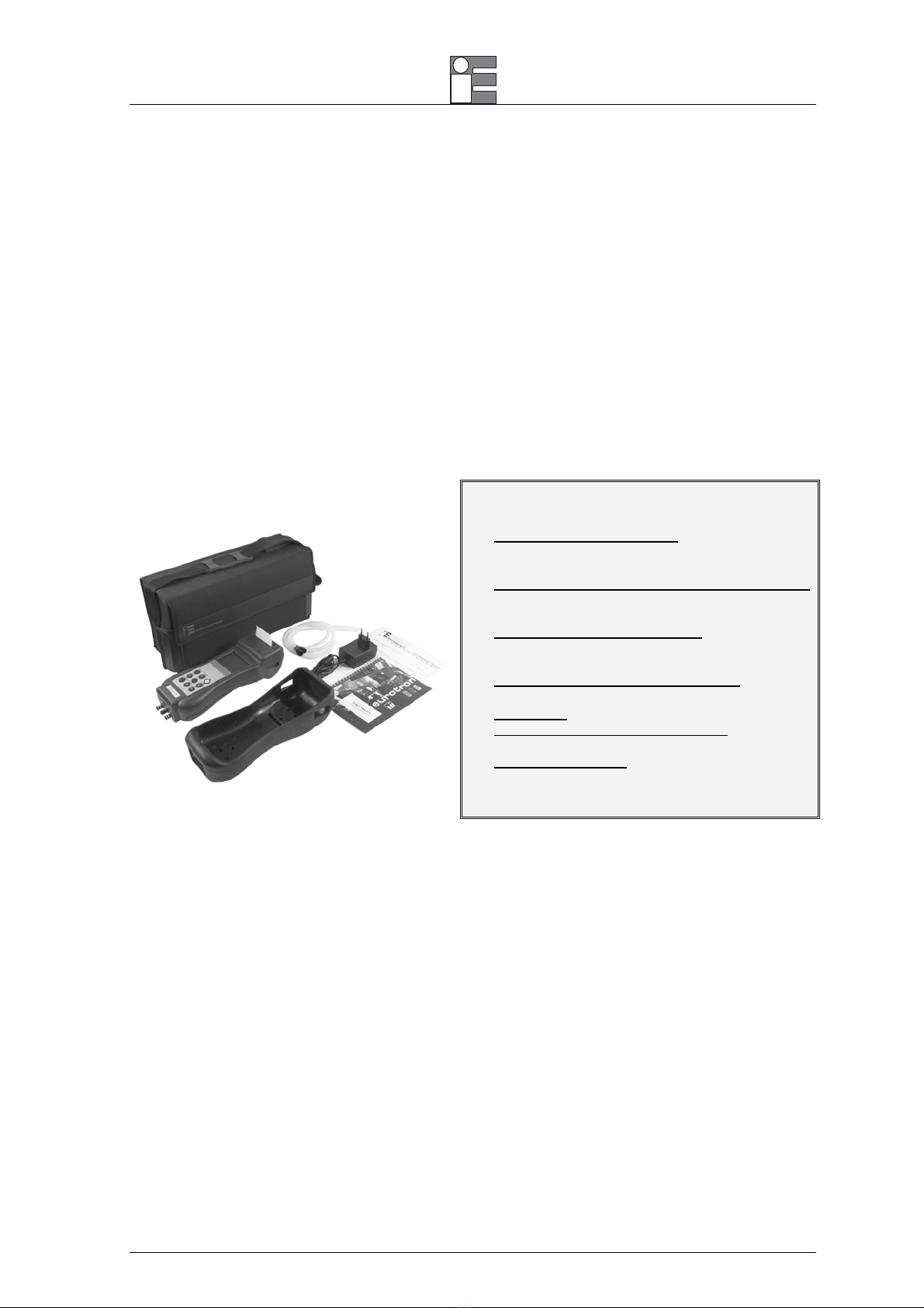
This manual includes all the information you need to install, operate and maintain the flue gas
analyzer UniGas 1000, BTU 1000 and its accessories.
Eurotron has used the best care and efforts in preparing this book and believes the information in
this publication are accurate. The Eurotron products are subjected to continuous improvement, in
order to pursue technological leadership; these improvements could require changes to the
information of this book.
Eurotron reserves the right to change such information without notice.
The gas analyzer uses sophisticated analogic and digital technologies. Any maintenance operation
must be carried out by qualified personnel ONLY. Eurotron supplies instructions and operative
procedures for any operation on the instrument. We recommend contacting our technicians for any
support requirements and questions.
The instrument is supplied by a rechargeable battery pack or by 100, 115, 230V
±
10% 50/60Hz
main power supply.
The instrument is fully tested in conformity with the directive n°89/336/CEE Electromagnetic
Compatibility. Eurotron shall not be liable in any event, technical and publishing error or
omissions, for any incidental and consequential damages, in connection with, or arising out of the
use of this book.
The operator must not use this equipment for any other purpose than that stated.
This document is the property of Eurotron and may not be copied or otherwise reproduced,
communicated in anyway to third parties, not stored in any Data Processing System without the
express written consent of Eurotron
All right reserved
Copyright © 2004, 06
EUROPEAN Headquarters
Eurotron Instruments SpA
Viale F.lli Casiraghi 409/413
20099 Sesto S. Giovanni (MI)
Tel. : +39-02 24 88 201
FAX: +39-02 24 40 286
USA Headquarters
E-Instruments Group LLC
172 Middletown Blvd – Suite B201
Langhorne, PA 19047
Tel.: 215 750 1212
FAX: 215 750 1399

Manual instruction MM850482 ed.04
3
TABLE OF CONTENTS
1GENERAL DESCRIPTION................................................................................................... 4
1.1 Ordering Code ..................................................................................................................................... 5
1.2 Specifications ...................................................................................................................................... 5
1.3 Calibration certificate ........................................................................................................................... 6
1.4 Electromagnetic compatibility .............................................................................................................. 6
2PHYSICAL DESCRIPTION................................................................................................... 7
2.1 Keyboard ............................................................................................................................................. 8
3PRINCIPLE OF OPERATION............................................................................................... 9
3.1 Measurement Principle ........................................................................................................................ 9
3.1.1 Gas Sampling Probe....................................................................................................................... 9
3.1.2 Water Trap & Line Filter................................................................................................................ 10
3.1.3 Gas Sensors ................................................................................................................................. 10
3.2 Auxiliary Measurements .................................................................................................................... 11
3.2.1 Temperature Measurements......................................................................................................... 11
3.2.2 Pressure and Draft........................................................................................................................ 11
3.2.3 Smoke Index Measurement (optional) .......................................................................................... 12
3.2.4 Measuring Instruments (optional) ................................................................................................. 12
4RECOMMENDATIONS....................................................................................................... 13
4.1 Power supply ..................................................................................................................................... 13
5CONNECTIONS.................................................................................................................. 14
5.1 Electro-pneumatic connections.......................................................................................................... 14
5.2 Gas probe positioning........................................................................................................................ 14
6OPERATIONS..................................................................................................................... 16
6.1 Flue Gas Analysis.............................................................................................................................. 16
6.1.1 Switch the instrument ON ............................................................................................................. 16
6.1.4 Pressure/Draft Measurement........................................................................................................ 19
6.1.4.1 Differential Pressure Measurement.......................................................................................... 21
6.1.5 Draft with External Probe (optional) .............................................................................................. 21
6.1.6 Temperature Measurement .......................................................................................................... 23
6.2 Leak Test Procedures........................................................................................................................ 24
6.2.1 Let-by Test.................................................................................................................................... 24
6.2.2 Tightness test ............................................................................................................................... 26
6.2.3 Pressure Kit EE300248................................................................................................................. 27
6.3 Smoke Measurement......................................................................................................................... 27
6.4 Analysis Data Print ............................................................................................................................ 29
6.4.1 Built-In Printer (option) .................................................................................................................. 29
6.5 Carbon Monoxide Safety Room Test................................................................................................. 32
7CONFIGURATION.............................................................................................................. 34
7.5 Update Instrument to Instrument (Bootload)......................................................................................39
8MAINTENANCE.................................................................................................................. 40
8.3 Error Messages ................................................................................................................................. 41
8.5 Accessories and Spare Parts ............................................................................................................ 42
9CERTIFICATES .................................................................................................................. 43
9.1 Warranty Terms................................................................................................................................. 43
9.2 Letter of Conformity ........................................................................................................................... 43
APPENDIX....................................................................................................................................... 44
A1 EMC Conformity ................................................................................................................................ 44
INDEX............................................................................................................................................... 46
Manual instruction MM850482 ed.04
4
1 GENERAL DESCRIPTION
UniGas 1000 is designed to satisfy the HVAC market needs; but it is the result of the advanced research and
experience of Eurotron has been developing and manufacturing portable flue gas analyzers since 1986.
The UniGas 1000 is a multi-gas, compact, Hand-held, multifunctional instrument. The micro-processor based
instrument includes a flue gas analyzer, and an ambient parameters indicator. Two internal electrochemical
sensors read the Oxygen (O2) and carbonic monoxide (CO) gas concentration. The gas temperature and air
temperature are used in connection with the gas analysis to calculate the efficiency, excess air, and CO2
concentration. A 10-gas parameters programmable table is used for calculations approved in accordance with
DIN33962.
The instrument is completed with a differential pressure (draft) sensor.
♦Draft measurement is possible using the internal pressure sensor and the Eurotron Group special gas
sampling probe.
♦The optional internal printer is impact type and the generated document is very legible and has long time
shelf life.
♦The UniGas has a standard IR serial interface for external HP 82240B thermal wireless printer.
Features & Benefits
New user-friendly interface: very intuitive and in
English language to use the instrument without
instruction manual.
Large dimensions and lighting LCD display:
very legible, large format, with automatic and
manual backlight device.
Easy and quick upgrading hardware and
software are made using modular design to
upgrade the system yourself.
Differential pressure measurement: pressure,
draft, ∆P, etc.
Averaging between three or more gas analysis.
Built-in impact type printer (option): more legible
and long-time duration for you documents.
Single battery pack: rechargeable to power both
the instrument and the internal printer.

Manual instruction MM850482 ed.04
5
1.1 Ordering Code
UniGas 1000 / BTU 1000 7820 – A – B – C – D – E – F
Each Instrument is equipped standard with differential pressure and draft sensor, Tc gas temperature input, Pt100
combustion air temperature input, IR printer port, real-time clock capabilities, rechargeable battery pack, battery charger and
supplied with a Report of Calibration and an instruction manual.
Table A Sensor n.1
1 O2(0-25%)
Table B Sensor n.2
0 None
2 CO (0-4000 ppm), EN50379-3
2H CO (0-8000 ppm) H2compensated, EN50379-2
Table C Flue gas probe (line filter and water trap included)
1 180mm flue gas probe or draft (single hose) BB610047
2 300mm flue gas probe or draft (single hose) BB610048
Table D Option
0 None
P Built-in impact printer
Table E Mains adapter / charger
1 115V ±10% 50/60Hz - USA plug
2 230V ±10% 50/60Hz - Schuko plug
3 230V ±10% 50/60Hz - UK plug
4 230V ±10% 50/60Hz - European plug
5 100V ±10% 50/60Hz - USA/Japan plug
Table F Calibration certificate
1 Eurotron report
1.2 Specifications
•Type: 1 or 2 cells Hand-held flue gas analyzer.
•Calibration: automatic calibration procedure at 60 seconds with smart autozero switch-On.
•Self-diagnosis: Sensors efficiency test with diagnostic messages display.
•Fuel types: Up to 10 selectable from keyboard (most common preprogrammed).
•Pump: rate of flow 0.8 lit / head –70mbar - All data measured using 3 meters long probe and line filter
connected. Load loss = 10 mbar using a 3 meters probe extension
•Power supply: High capacity Ni-MH rechargeable battery pack / external battery charger.
•Charging time : 8h at 90% with instrument off.
•Battery life: 6h continuous operation (without printing and back-light).
•Printer power supply: from the analyser battery pack.
•Printer Report Header: 4 programmable lines.
•Display: 40x58 mm alpha-numeric LCD with backlight device.
•Infrared port: compatible with HP82240B wireless printer
•Smoke measurement: Using the optional external manual pump.Index memory store and printout
capability as standard.
•Flue gas Probe: stainless steel with rubber handle and incorporated temperature sensor. 2 meters long
rubber hose included.
•Water trap: external with purge plug and filter.
•Line filter: with replaceable cartridge.
•Working temperature: from –5°C to +45 °C (up to 50°C for short time)
•Storage temperature: from –20 to +60°C (3 months maximum at temperatures exceeding the operational
limits).

Manual instruction MM850482 ed.04
6
•Dimensions: 115x90x330 mm
•Weight: 1.1 kg (battery and printer included)
•Warranty: 2 years for sensors, connectors, battery, printer and pump.
Accuracies and Ranges
Parameter Sensor Type Range Resol. Max
Response Accuracy
O2Electrochemical from 0 to 25.0% 0.1% 20 sec. ±0.2% Vol.
CO
Electrochemical from 0 to 4000 ppm 1 ppm
50 sec.
±10 ppm < 300ppm
±4% rdg. up to 4000 ppm
CO
H2compensated
Electrochemical from 0 to 8000 ppm 1 ppm
50 sec.
±10 ppm < 300ppm
±4% rdg. up to 2000 ppm
±10% rdg. elsewhere
CO2Calculated from 0 to 99.9 % 0.1 %
Tair Pt100 from -10 to 100 °C 0.1 °C ±0.5 °C
Tgas Tc K from 0 to 600.0 °C 0.1 °C ±1 °C
∆T Calculated
Pressure / draft Piezoresistive from -10 to 120 hPa 0.01 hPa ±3Pa <300 Pa
±1% rdg. elsewhere
Excess air Calculated from 1.00 to infinite 0.01
Efficiency Calculated from 0 to 120% 0.1 %
(also for condensing boilers with automatic detection)
Smoke index External pump from 0 to 9
All emission measurements can be displayed with reference to a programmable O2 value.
The relative accuracy shown are expressed as absolute or % of rdg errors at -5°C to +40°C ambient temperature.
The maximum response time shown is referred to 90% signal changes.
The pressure relative accuracy shown is valid only after the auto-zero procedure
Accuracy limits are stated as % of reading. An additional ±1 digit error has to be considered.
The stated pressure relative accuracy is valid only after the zero procedure.
Measuring reading can be directly converted from °C to °F, ppm to mg/Nm3 and from hPa to mmH2O, mbar, inH2O.
Specifications may change without notice.
Fuel technical data
The instrument includes as standard the technical data for 4 of the most common fuels.
Up to 10 fuel types can be set up by factory on demand.
1.3 Calibration certificate
Each UniGas 1000 portable gas analyzer is factory calibrated and certified against Eurotron Standards that
are periodically certified by an International recognized Laboratory, and shipped with a Report of Calibration
stating the nominal and actual values and the deviation errors.
1.4 Electromagnetic compatibility
The instrument case, made in shock-resistant injection molded ABS + polycarbonate has designed to fulfill the
directive 89/336/CEE Electromagnetic Compatibility. See Appendix A1 for EMC declaration of conformity.
Manual instruction MM850482 ed.04
7
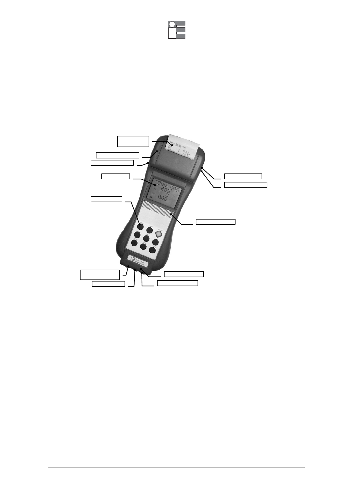
2 PHYSICAL DESCRIPTION
The UniGas portable analyzer consists of a rugged and compact case, a mother board with all base function
circuits, 1 or 2 electrochemical cells, a gas pump, a keyboard, an LCD back-lit display, a Ni-MH rechargeable
battery pack and, optionally, an impact printer.
The 2 pieces of the case are jointed by 8 screws. The batteries, the pneumatic circuit and the cells are
positioned in the rear of the analyzer and 2 screws locking the lid.
A pressure lid allows easy removal of the paper roll.
Built-in optional
impact printer
LCD Display
Rubber keyboard
Tgas Tc K probe input
∆P in
p
ut
(
P2
)
Draft/Pressure input
(P1)
GAS INLET
Printer wireless port
Charger connector
Tair Pt100 probe input
Back-light sensor
External probe input
At the bottom of UniGas 1000 you can see all sampling probe connectors: gas inlet, and differential pressure /
draft inputs.
On the left side are the connectors for: line power charger and IR serial port for external wireless printer.
On the right side are the connectors for: auxiliary probes, the thermocouple type K for flue gas temperature.
The operator interface is on the front of the instrument and it consists of: a high contrast LCD display and a 9
button keypad. An automatic backlight device makes reading the data on display much easier.
Manual instruction MM850482 ed.04
8
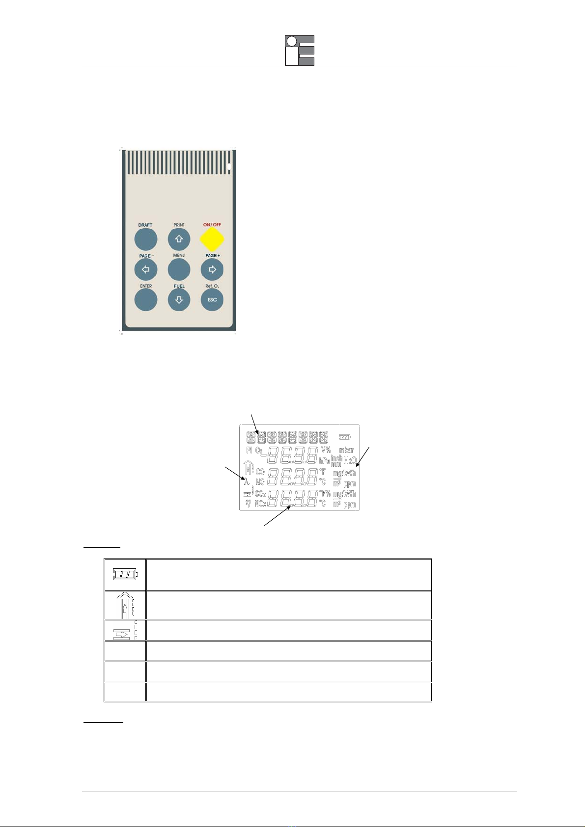
2.1 Keyboard
The front panel keys functions are the following:
2.2 Display
UniGas is designed with a large (40x56 mm) graphical display using an automatic backlight system for the
best reading in poor light conditions also.
Values
Symbols
Engineering
Units
Messages
Symbols
The display has graphical symbols to describe the actual operation mode of the UniGas 1000.
Battery status: fully black=charged; empty=needs charging
The symbol is flashing when battery is charging
Flue gas temperature
Ambient/combustion air temperature
λ Excess air
η
Efficiency
PI Poison Index. CO/CO2Ratio
Backlight
To increase the display readability, an automatic backlight device is included.
[ON/OFF] Switches the analyzer on or off.
[],[],[],[] Increase or decrease numerical
values.
[ENTER] Accepts and memory stores memory
modified parameters or variables.
Pressing this key from the analysis
page, the internal pump will be
switched on and off.
[PRINT] Goes to the Printout menu page.
[MENU] Goes to the auxiliary functions menu.
Scrolls among menu options.
[ESC] Return to the gas analysis function.
[DRAFT] Goes directly to draft/pressure
measurements page.
[FUEL] Goes directly to fuel selection page.
[Ref. O2] Displays the CO measurement as
referred to the specified oxygen
percentage.
Manual instruction MM850482 ed.04
9
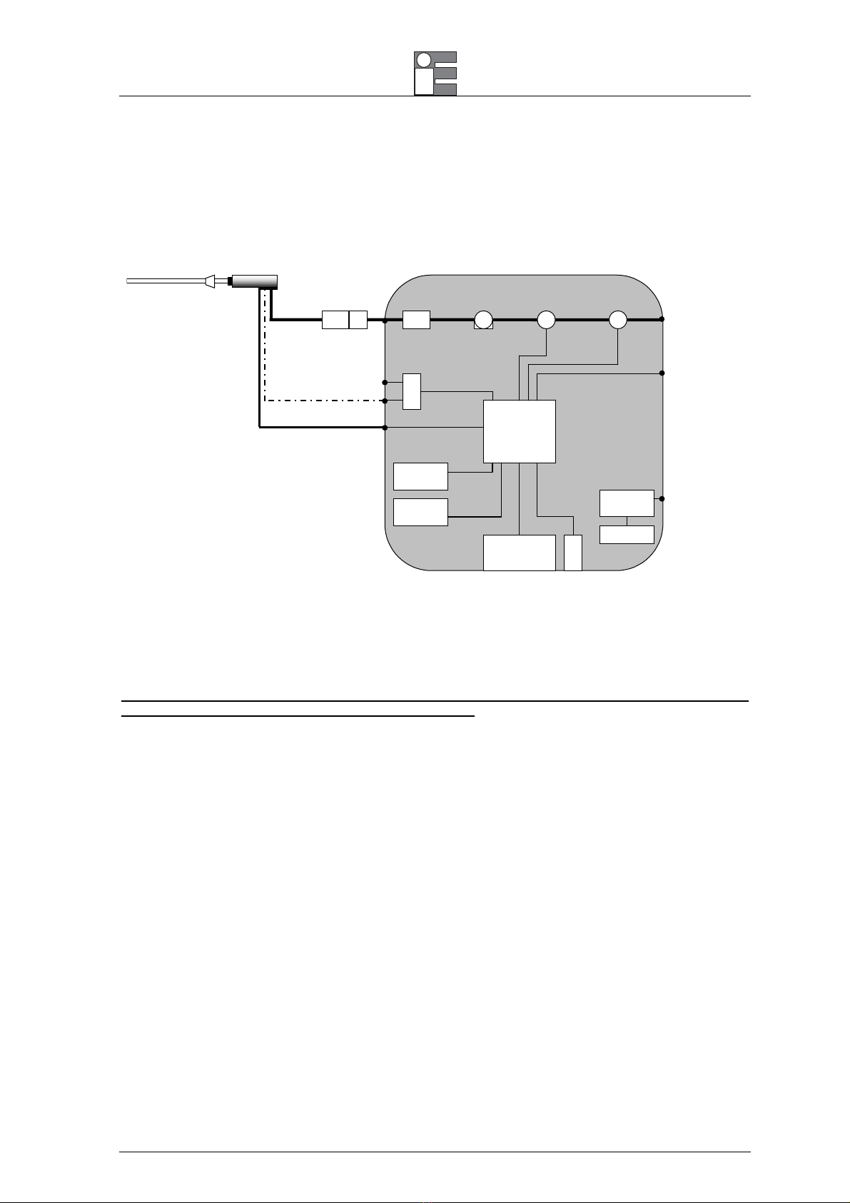
3 PRINCIPLE OF OPERATION
UniGas 1000 analyzer is based on the following functional blocks:
MicroController
Built-in Impact
Printer
Keyboard
Display
Power supply
Ni-MH
batteries
Charger connector
Pt100 Tair probe input
Gas Outlet
IR printer port
P2 - ∆P
P1 – Draft/Pressure
Differential
pressure
sensor
Gas INLET Pump
1th Sensor O2 2nd Sensor CO
Methan sensor
TcK T
g
as in
p
u
t
Water trap
Line Filter
3.1 Measurement Principle
The gas is sampled and aspirated through the probe with a primary pump powered at constant voltage.
To position the sampling probe in the exhaust gas pathway a hole of 11mm, up to 16mm, should be drilled
and the retaining cone of the sampling probe firmly screwed in it.
The retaining screw in the cone enables the probe to be easily moved to locate the core flow, normally
correspondent to the center of the section of the chimney. The flue gas and exhaust gas pathway, should
be checked for gas-tightness before carrying out a measurement and, if necessary, non gas-tight points
should be sealed.
The O2sensor is essentially an electrochemical cell, with two electrodes and electrolyte solution. The
behaviour is similar to a normal battery and therefore the sensitivity decreases with time.
The electrochemical cell grants accurate results for time intervals of approximately 60 minutes. The zero drift
is automatically corrected by UniGas every time the instrument is switched-on, using fresh ambient air as
reference. This operation should be made with the sampling probe not inserted in the chimney or with the
sampling probe pneumatic connector disconnected from the analyzer gas inlet.
When a long time analysis has to be made, a new autozero procedure should be performed.
Measured and calculated parameters are indicated on a LCD alphanumeric display (40x56 mm), equipped
with an automatic back light device for easy readings, also in poor light conditions.
3.1.1 Gas Sampling Probe
The sampling probe consists of a steel tube and a handle of thermo insulating material. A positioning cone
allows placing the probe in holes with a diameter from 11 to 16 mm.
The gas temperature is acquired using a thermocouple type K with the junction placed on the top of the tip.
Manual instruction MM850482 ed.04
10
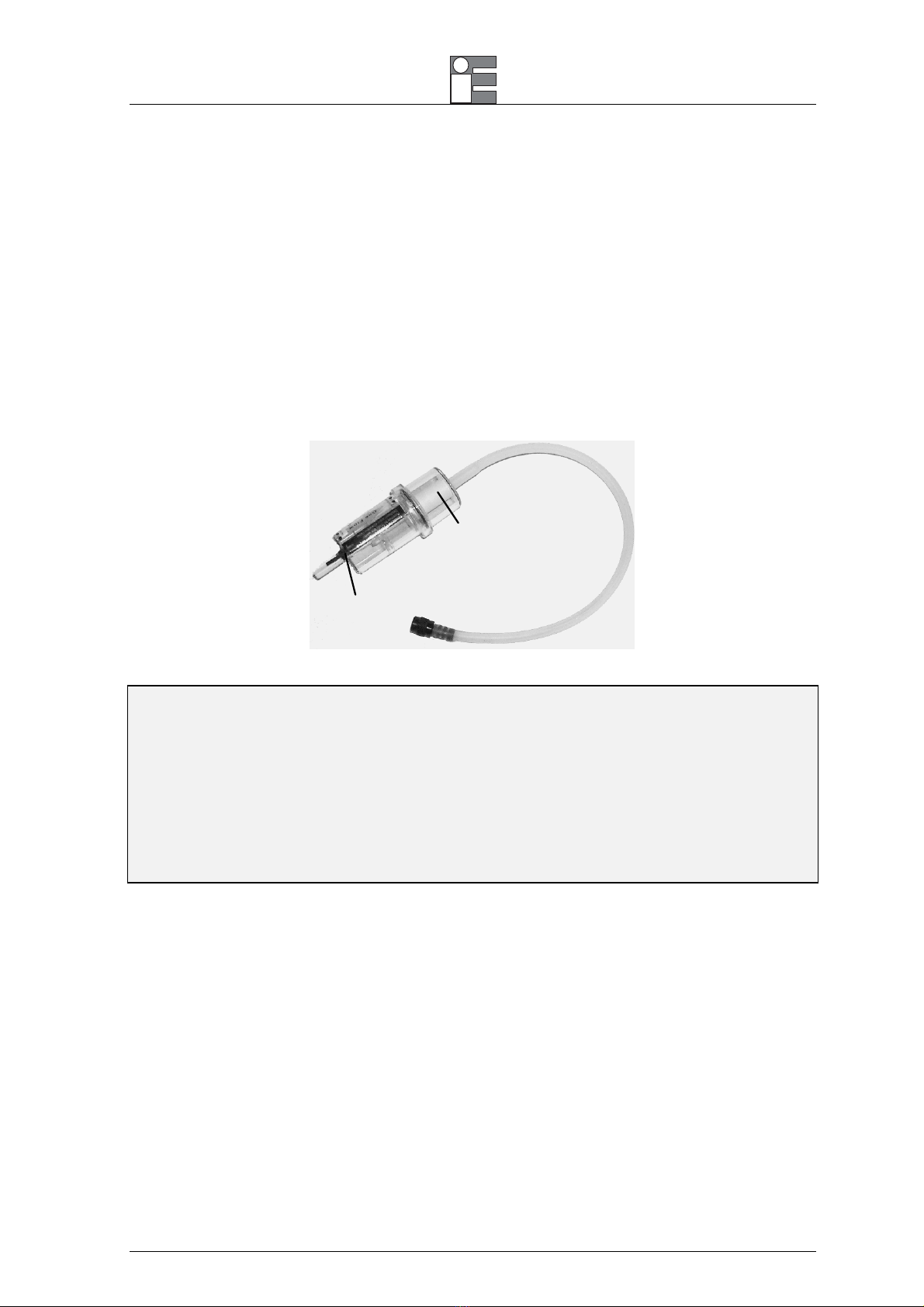
3.1.2 Water Trap & Line Filter
The gas flows through an external combined water trap and line filter to avoid the presence of condensation
and suspended solid particles in the analysis section of the instrument. A cylinder is positioned at 15 cm from
the instrument gas inlet it is divided into two parts: the water trap and the line filter.
The water trap works using the expansion principle: the gas flow decreases its speed inside the cylinder and
it will cool; the humidity will condense and the solid particles fall down. The section of the water trap must be
periodically drained off to avoid water from entering the analysis section. Pull the rubber plug (cat. EE650081)
and shake slowly the trap to drain the water. Push the rubber plug to close the trap hole.
The line filter is positioned after the water trap and before the electrochemical cell. Its function is to stop the
smallest solid particles before the analysis. Remember to change the filter (cat. EE650074) every time it is
dirty.
Line filter
cat. EE650074
Rubber plug
cat. EE650081
WARNING
THE WATER TRAP MUST BE KEPT IN VERTICAL POSITION DURING GAS SAMPLING.AN INCORRECT POSITIONING OF THE
TRAP CAN ALLOW THE WATER TO ENTER INSIDE THE ANALIZER AND DAMAGE THE ELECTROCHEMICAL SENSORS.
NEVER MAKE ANY ANALYSIS WITHOUT THE DRAINING RUBBER PLUG.THE MEASUREMENTS WILL BE INCORRECT.
WHEN YOU FINISH THE ANALYSIS,REMEMBER TO DRAIN THE WATER TRAP.BEFORE PUTTING THE GAS PROBE IN THE
CARRYING CASE,REMOVE THE CONDENSATE WATER FROM THE PROBE HOSE.
THE LINE FILTER SHOULD BE REPLACED WHEN DIRTY.NEVER MAKE ANY ANALYSIS WITHOUT LINE FILTER AND/OR WATER
TRAP,AS IT CAUSES AN IRREVERSIBLE DAMAGE TO THE ELECTROCHEMICAL SENSOR.
3.1.3 Gas Sensors
The analyzer uses long life sensors for O2and CO measurements. The gas sensors are electrochemical cells
composed by two electrodes (anode and cathode) and an electrolyte solution. The sampled gas goes trough a
selective diffusion membrane. The oxidation process produces an output electrical signal proportional to the
gas concentration. The signal is evaluated by the electronics, converted to digital, processed by the
microprocessor, displayed and printed with a 0.1% volume resolution.
The flue gas must not be at a pressure that could damage or destroy the sensor. Measurements are always
carried out under "pressureless" conditions. The maximum permissible excess/reduced pressure is ±100
mbar.
Each sensor has a different response time:
O2= 20s to 90% of reading
CO (H2 comp.) = 50s to 90% of reading
CO = 50s to 90% of reading

Manual instruction MM850482 ed.04
11
NOTE:TO OBTAIN AN ACCURATE MEASURE IT IS RECOMMENDED TO WAIT 3-5 MINUTES.
If an excessive (>150% of F.S.) gas concentration is applied to toxic gas sensor, then a ±2% drift and a long
resuming time can be present. In that case it is recommended to wait for a measured value lower than 20
ppm, by sucking fresh air before switching the analyzer off.
Four acoustic and visual alarm levels can be set on four programmable parameters.
3.2 Auxiliary Measurements
3.2.1 Temperature Measurements
The instrument is equipped with two temperature inputs to measure exhaust gas and the burner air input
temperatures (combustion gas).
♦A thermocouple type K (nickel-nickel chromium) is included in the tip of the gas sampling probe to
measure the flue gas/exhaust gas temperature. This thermocouple is suitable for permanent
measurements at temperatures up to 800°C and for short-term measurements up to 1000°C.
Temperature measurement and gas sampling from the flue gas pathway are thus always performed at the
same site. The probe is connected to the apparatus with compensated cable and connector. An internal
Pt100 resistance thermometer is used for cold junction compensation.
♦A remote Pt100 sensor can be supplied on request with a 2-meter cable to measure the air inlet
temperature in forced air boiler. This option is very important for an accurate efficiency calculation.
3.2.2 Pressure and Draft
The analyzer is equipped with a temperature compensated pressure sensor to measure the chimney draft or
pressure. The pressure/draft sensor is based on the principle of the extension metric measuring bridge. The
pressure range is -100 to 100mbar. The sensor is factory calibrated and does not require manual adjustment.
The zero drift, caused by ambient air temperature variation, is automatically cancelled at each instrument
start-up. In addition, for more accurate readings the operator can reset, using the pertinent key, the zero if
required. Leave open the “∆P” connector during this phase.
NOTE:WE SUGGEST EXECUTING THE AUTOZERO PROCEDURE FOR MORE ACCURACY BEFORE PERFORMING THE
MEASUREMENT.
CAUTION
IF A SINGLE TUBE GAS SAMPLING PROBE IS USED FOR PRESSURE/DRAFT MEASUREMENTS,BE SURE THAT IT IS CLEAN AND
DRIED BEFORE CONNECTING TO THE PRESSURE INPUT.
CAUTION
A+300HPA (OR –300HPA)OVER-PRESSURE CAN PERMANENTLY DAMAGE THE PRESSURE SENSOR.
Manual instruction MM850482 ed.04
12
3.2.3 Smoke Index Measurement (optional)
This method consists of taking a gas sample from the center of the gas pipe behind the heat exchanger and
crossing it through a special filter paper.
The color of the spot on the filter is compared with a graduated (from 0 to 9) reference scale and it is called
“smoke index”.
You can type into the instruments up to 3 smoke index values; the analyzer calculates the average value and
prints these values on the report.
Normative and laws about the air pollution, describes the procedure: DIN51402, 2116, 2117 and 2297 VDI
directives, ASTM D 2156-63 T, etc.
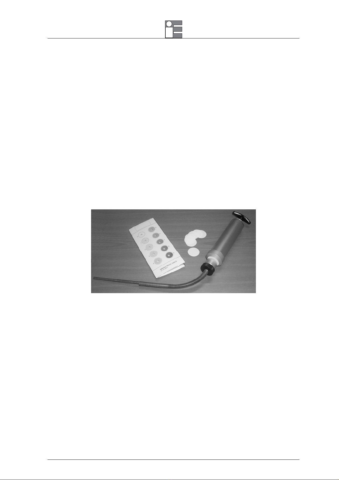
3.2.4 Measuring Instruments (optional)
1. Smoke pump: it should pull 1.63 liters ±0.07 l (normalized to 0°C, 760mmHg) through a 1 cm2filter.
2. Smoke index reference table: it is a grey scale sheet with 10 different areas numbered from 0 to 9. The
number 0 corresponds to an 85% ±2.5% reflection. Every area reflects 10% less than the previous one.
The scale is used to compare the scale with the paper filter and to calculate the smoke index.
3. Paper filter: When it is clean it has a reflection corresponding to the 0 scale index. It also has 3 liters per
cm2a minute (normalized to 0°C, 760mmHg) with a 200/800 mmwc resistance to the air flux.

Manual instruction MM850482 ed.04
13
4 RECOMMENDATIONS
The analyzer should be used in environments where the temperature is between -5°C and +45°C.
When the analysis are completed, before switch the instrument off, remove the probe from the gas
pathway and wait about 30 seconds cleaning the pneumatic circuit from gas.
Do not use the analyzer with clogged filters or filled with humidity.
Before placing the probe in the case, be sure that the probe, the water trap and the hose are clean and
cold.
If you have ordered a double hose sampling probe, insert both connectors to the instrument during the
gas analysis (pay attention to colour correspondence on hose plugs).
To empty the water trap from the condensate water, remove the draining plug. DO NOT OPEN the water
trap. DO NOT leave the water trap without the draining rubber plug (cat. EE650081).
For the best efficiency and accuracy, we suggest calibrating the instrument every year.
WARNING
IF THE UNIGAS IS STORED AT TEMPERATURE EXCEEDING THE OPERATIVE LIMITS,THE ANALYZER NEEDS SOME MINUTES
TO WARM-UP TO THE ACTUAL AMBIENT TEMPERATURE,BEFORE STARTING THE OPERATION.
4.1 Power supply
UniGas can be powered from:
internal rechargeable Ni-MH battery.
External battery charger, supplied as a standard accessory (the batteries must be installed).
Optional external DC auto battery charger (the batteries must be installed).
The Ni-MH rechargeable batteries allows a long operation time and do not need maintenance. The same
batteries power both the instrument and the internal printer. The internal battery will grant 6 hours continuous
operation (without printing and display back light off).
NOTE:90% BATTERY CHARGING CAN BE OBTAINED IN 8HOURS WITH THE UNIGAS SWITCHED OFF.
During operation a fully battery symbol “≠” will be displayed on the display. This symbol means that the
batteries are completely full. When the batteries will be discharged the symbol “–” will appear and the
instrument still has about 20 minutes operation capability to end the running analysis.
The battery symbol indicates that a full charge is required. Use only the dedicated battery charger supplied by
Eurotron together the instrument.
CAUTION: OLD BATTERIES CAN LEAK AND CAUSE CORROSION.NEVER LEAVE RUN DOWN BATTERIES IN THE
INSTRUMENT
WARNING
THE INSTRUMENT IS SHIPPED WITH AN AVERAGE LEVEL OF BATTERY CHARGE.AFTER UNPACKING,A FULL CHARGE OF THE
BATTERY IS RECOMMENDED,BY CONNECTING THE INSTRUMENT TO THE MAIN LINE THROUGH THE BATTERY CHARGER
(OFF CONDITION)FOR 8-10 HOURS AT A TEMPERATURE BETWEEN 10 AND 30°C
Manual instruction MM850482 ed.04
14
5 CONNECTIONS
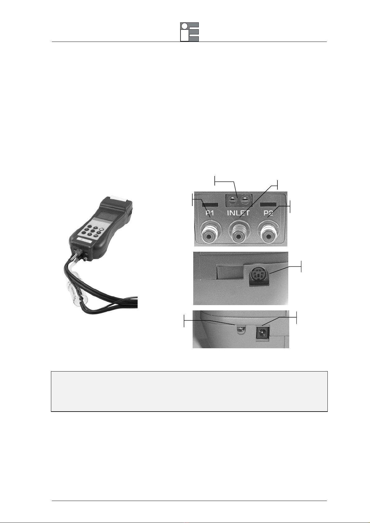
5.1 Electro-pneumatic connections
To prepare the instrument for operation, connect the sampling probe to the instrument:
•Plug the pneumatic connector of the probe to the GAS INLET connector. If you are using the gas
sampling probe with Draft option (double hose model), connect also the draft connector to the UniGas
Pressure/Draft inlet (P1).
•Plug the probe temperature sensor plug to the pertinent connector.
•If necessary, plug the remote air temperature Pt100 sensor to the pertinent connector.
Pneumatic connections
Right side
Left Side
P1 – Draft /pressure
input
GAS INLET
P2 – differential
p
ressure input
IR printer port
Tair input
Charger connector
Tgas input
WARNING
BEFORE STARTING THE GAS ANALYSIS PROCEDURE BE SURE THAT:
PROBE DRAFT CONNECTOR (P1) AND GAS SAMPLING CONNECTOR (INLET) ARE PLUGGED TO THE INSTRUMENT;
DRAINING PLUG IS WELL INSERTED IN THE WATER TRAP;
LINE FILTER IS CLEAN.
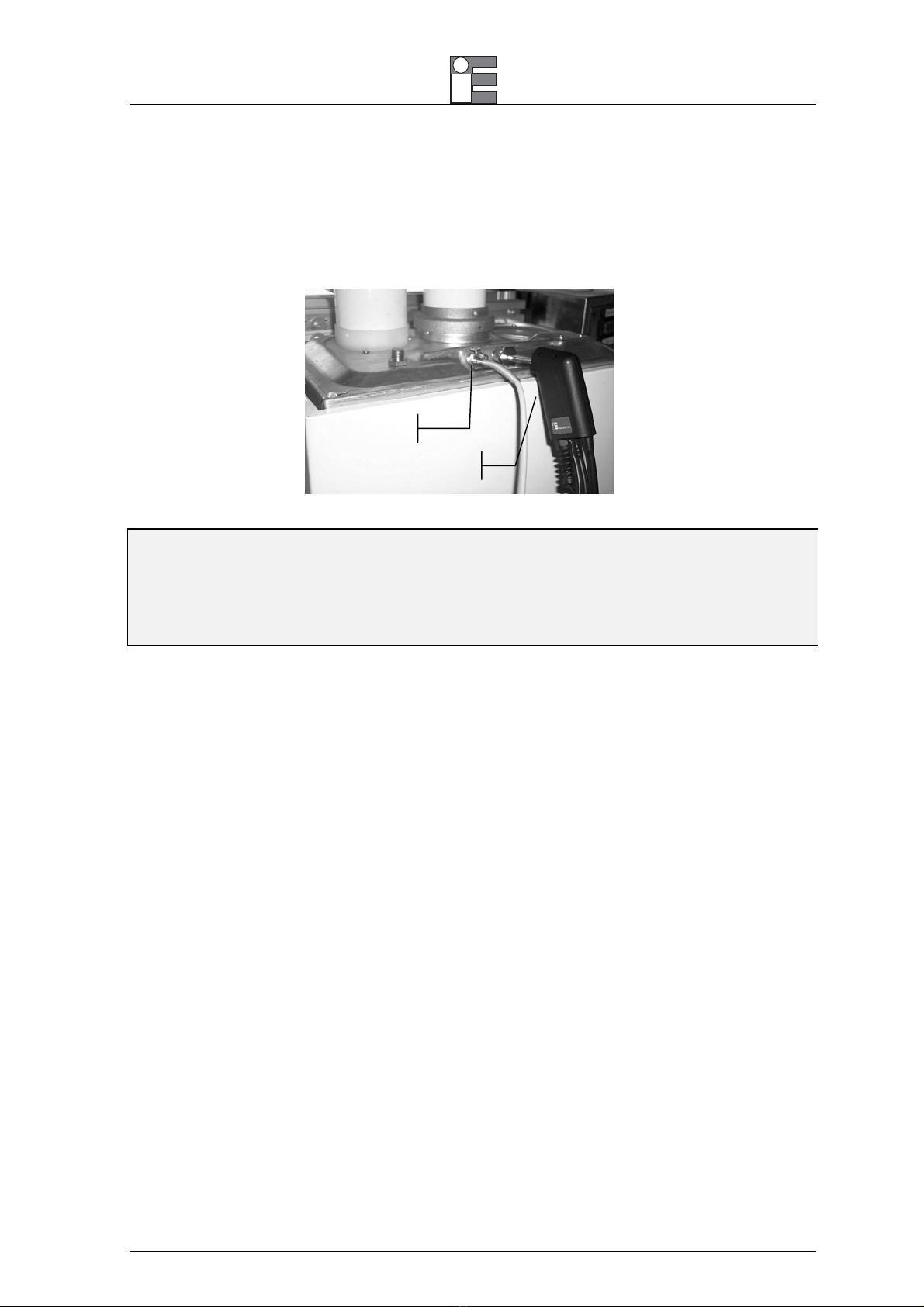
5.2 Gas probe positioning
The measurement site should be arranged at a distance of 2xD behind the exhaust gas connection pipe,
where D = diameter of the exhaust gas connection pipe.
To position the sampling probe in the exhaust gas pathway a hole of 11/16mm should be drilled and the
retaining cone of the sampling probe firmly screwed in it.
Manual instruction MM850482 ed.04
15
The retaining screw in the cone enables the probe to be easily moved in order to locate the core flow, normally
correspondent to the center of the section of the stack.
The flue gas and exhaust gas pathways must be checked for gas-tightness before carrying out a
measurement and, if necessary, non gas-tight points should be sealed.
To locate the gas core flow insert progressively the sampling probe and read the maximum value of
temperature.
Tair probe
Gas probe
CAUTION
FOR A CORRECT GAS ANALYSIS,NO AIR MUST REACH THE FLUE GAS AS A RESULT OF NON-GAS-TIGHT CONNECTION
POINTS BETWEEN THE HEAT PRODUCER AND THE MEASUREMENT SITE (PROBE).
THE FLUE GAS AND EXHAUST GAS PATHWAYS MUST BE CHECKED FOR GAS-TIGHTNESS BEFORE CARRYING OUT A
MEASUREMENT,AND IF NECESSARY NON-GAS-TIGHT POINTS SHOULD BE SEALED.
Manual instruction MM850482 ed.04
16
6 OPERATIONS
All the procedures and programming operations on UniGas 1000 can be made using the keyboard and the
display.
NOTE:ALL NUMERIC VALUES SHOWN IN THE FIGURES OF THIS MANUAL ARE INDICATIVE AND LISTED AS AN EXAMPLE.
The analyzer should be used in environments where the temperature does not exceed the specified limits
(from -5°C to +45°C) and where the relative humidity is lower than 95% non-condensing.
6.1 Flue Gas Analysis
6.1.1 Switch the instrument ON
Connect the gas probe to the analyzer as shown in chapter 6. DO NOT INSERT THE PROBE IN THE
CHIMNEY/ STACK WHEN UNIT IS GOIG THROUGH ITS 60 SECOND AUTO CALIBRATION.
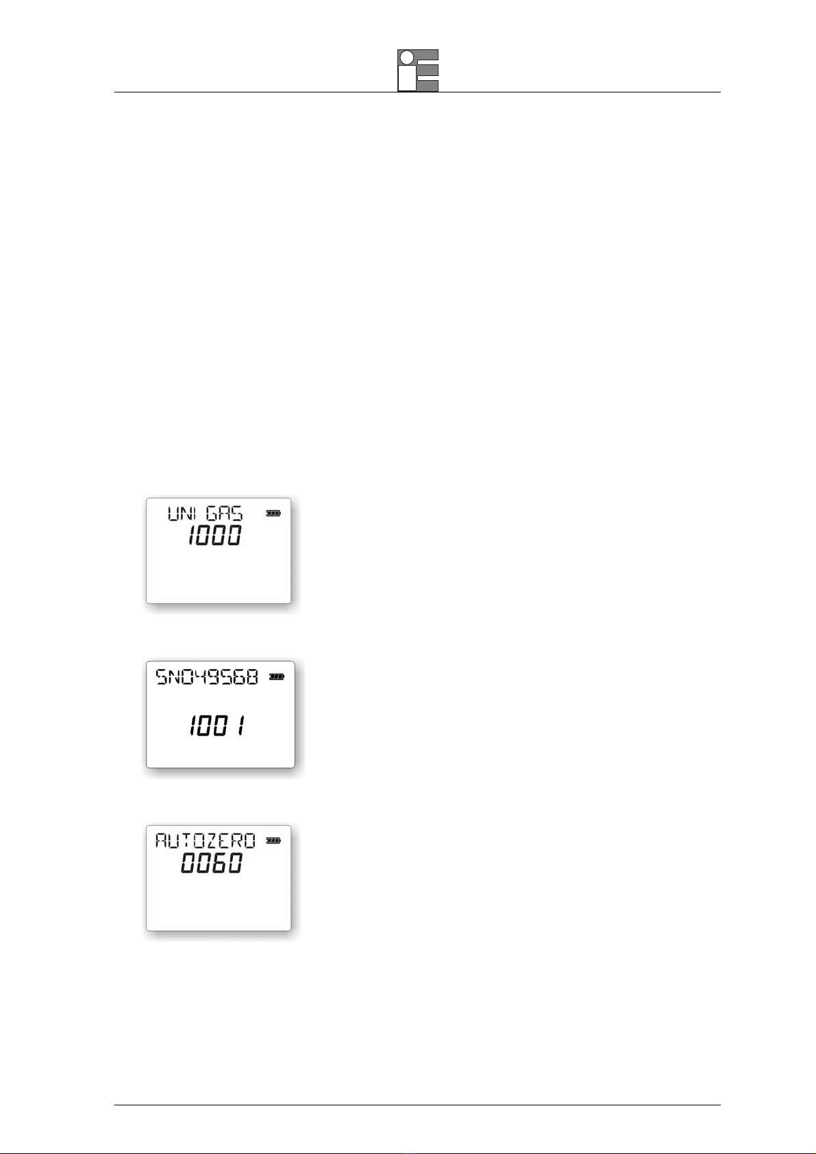
Switch the analyzer on pressing the [ON] key. The display will show the following page:
This page changes automatically after a few seconds or if you press a key as follows:
This page changes automatically after some a few seconds or if you press a key as follows:
This page displays the remaining seconds until the end of the autozero procedure.
NOTE: THE ANALYZER MUST DRAW CLEAN AMBIENT AIR FROM THE AMBIENT DURING THE AUTOZERO PROCEDURE.
OTHERWISE THE MEASUREMENTS MAY NOT BE ACCURATE AND A SENSOR ERROR MAY OCCUR.

Manual instruction MM850482 ed.04
17
When autozero procedure finishes, and no error occurs, a beeping sound advises the operator.
The standard autozero time is set for 60 seconds. If one or more sensors have a problem, the unit will
perform another autozero procedure.
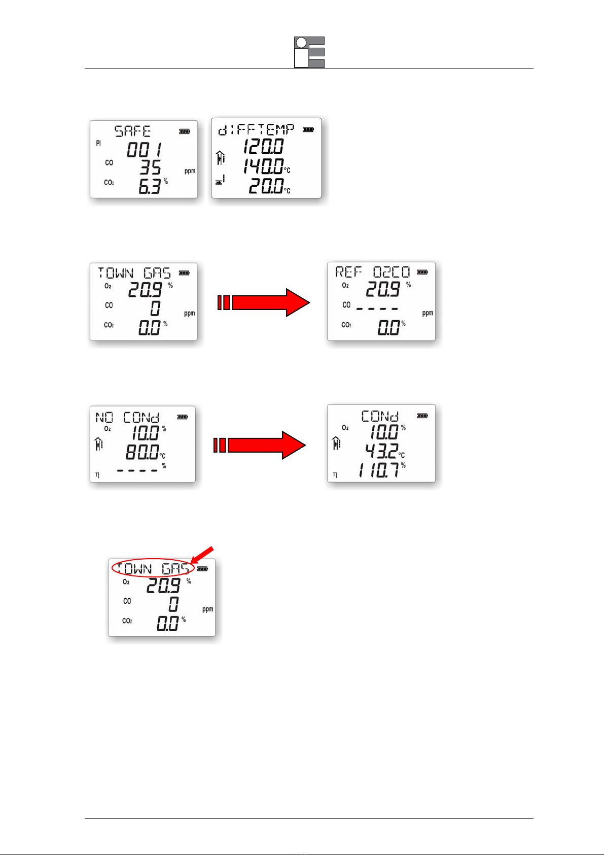
Press the [ENTER] key to mute the unit. The following page will be displayed:
The BTU/UNIGAS 1000 is now fully ready for flue gas analysis and any other measurements.
NOTE: AFTER THE INSTRUMENT IS SWITCHED ON,ALL SETTINGS WILL BE SET TO HOW IT WAS WHEN IT WAS TURNED
OFF.
6.1.2 Flue Gas Analysis
Insert the probe in the chimney. Stop using the retaining cone and adjust the immersion depth for a gas
sampling in the middle of the exhaust gas connection pipe.
Plug the pneumatic connector of the probe to the GAS INLET connector. If you are using the gas
sampling probe with Draft option (double hose model), connect also the draft connector to the UniGas
Pressure/Draft inlet (P1).
Plug the temperature connector of the sampling probe to the pertinent TcK connector.
If required, plug the remote air temperature Pt100 probe to the pertinent connector. It is important to
measure the true combustion air temperature to have a correct boiler efficiency calculation. Unigas has
an auxiliary Rtd input to measure simultaneously the air temperature. A Pt100 with a 2 meters long cable
can be connected on the right side of the analyzer. Insert the Rtd inside the air combustion aspiration
tube and near the boiler. The UniGas will show the temperature on the display and the efficiency will be
calculated using this value. If no external Rtd is connected, the analyzer will measure the instrument
temperature (ambient) using the internal sensor.
Pressing the [] and [] keys you can change page to display all other parameters
Manual instruction MM850482 ed.04
18
By pressing the [REF. O2] key, the measured parameters will be referred to the user defined programmed
oxygen value. When selecting this mode, the first line on the top of the display will be replaced by the
message “REF O2CO”.
NOTE: THE INSTRUMENT AUTOMATICALLY DETECT A CONDENSATING OR A NOT CONDENSATING BOILER.IF A
CONDENSATING BOILER IS DETECTED,THE DISPLAY WILL CHANGE AS FOLLOWS,AND THE CONDENSING EFFICIENCY VALUE
WILL BE DISPLAYED:
6.1.3 Fuel Type Set-Up
In the measuring page the set fuel type is displayed on the first row
To change the fuel type use the following procedure:

Manual instruction MM850482 ed.04
19
Press the [FUEL] key to display the following page:
Use the [] and [] keys to change the fuel type
Press the [ENTER] key to store the value.
Press [ESC] to return to the measure page.
6.1.4 Pressure/Draft Measurement
The UniGas 1000 has a built-in internal differential pressure sensor. With this sensor, you can execute the
pressure/draft measurements by using the standard probe or the special dual-hose probe.
Standard single hose probe:
The standard probe has one gas collector for gas sampling. Usually you have the hose terminal connected to
the gas inlet; when you have to do the draft measurements you have to move the connector to the pressure
inlet (INLET) connector (PI).
Special dual hose probe:
This special probe model has two gas collectors: one is for the flue gas analysis and the other one is for the
draft measurement. When connecting the probe to the analyzer be sure to connect both the gas inlet (INLET)
and pressure inlet (P1) connectors. Connect the hose with the line filter to the gas inlet connector.
CAUTION
IF YOU USE A SINGLE TUBE GAS SAMPLING PROBE FOR PRESSURE/DRAFT MEASUREMENTS,BE SURE THAT PROBE AND
THE HOSE ARE CLEAN AND DRY BEFORE CONNECTING THEM TO THE PRESSURE INPUT.
Manual instruction MM850482 ed.04
20
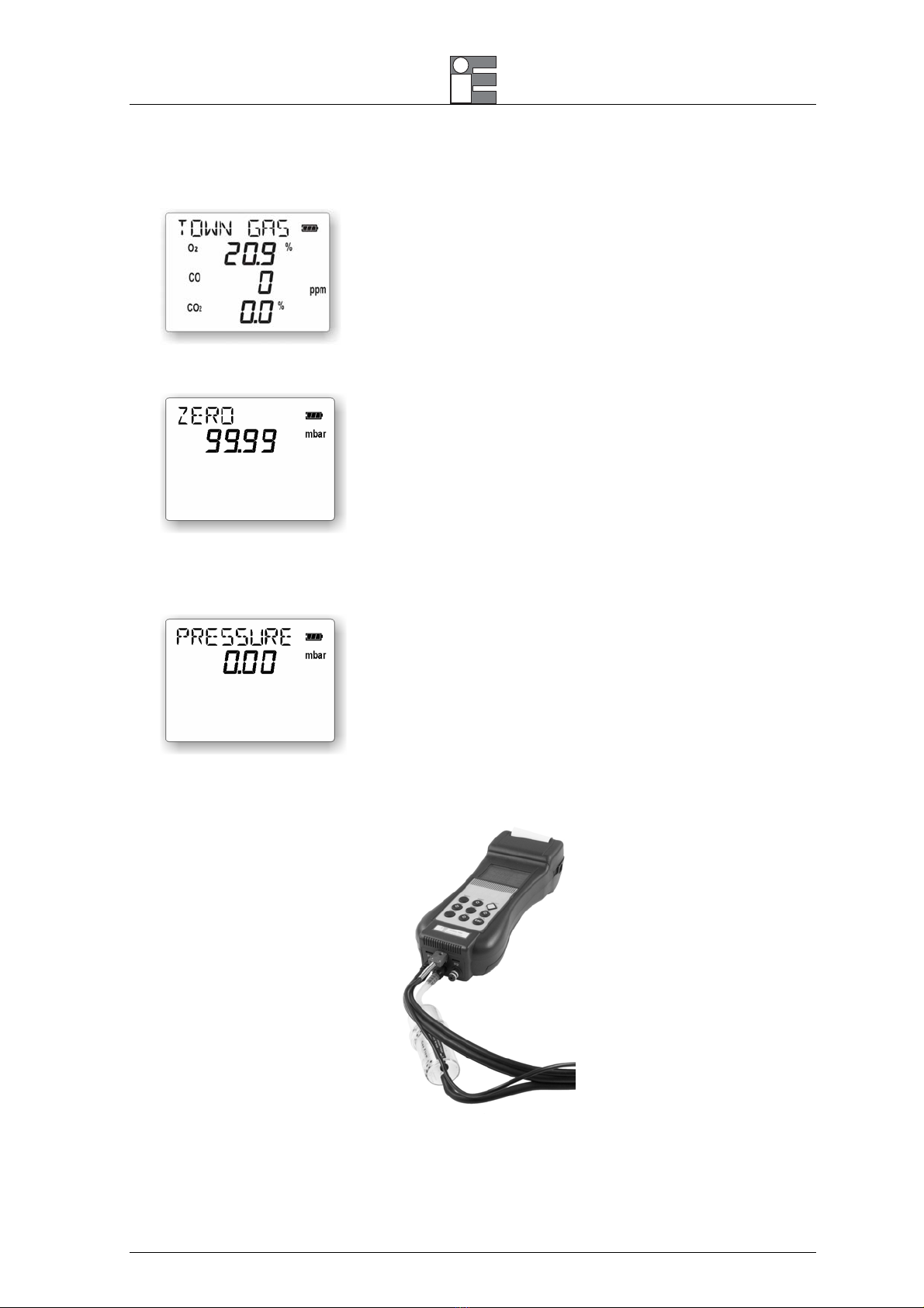
From the main page
•Press the [DRAFT] key:
NOTE: DO NOT INSERT THE PROBE INSIDE THE STACK.
•Press the [ENTER] key before inserting the probe in the stack to zero out the measured value.
•Insert the probe in the stack. Check for mechanical positioning and flue gas intercepting. Wait for
measurement stabilization.
NOTE: TO STORE THE DRAFT VALUE AND PRINT IT ON THE FLUE GAS ANALYSIS REPORT,PRESS THE [DRAFT] KEY.THE
PRESSURE PAGE WILL CHANGE AS FOLLOWS AND THE "M" SYMBOL WILL BE DISPLAYED.
This manual suits for next models
1
Table of contents
Other Eurotron Measuring Instrument manuals


