Eurovema Euroflex User manual

Work chair
User Manual, English
part no. BRU-80-120. Rev: 202200124

2
CONTENTS
Introduction.......................................................... 3
Assembly.............................................................. 3
User information .................................................. 3
Safety instructions............................................... 3
Service/Guarantee............................................... 4
Cleaning ............................................................... 4
Function................................................................ 4
Storage.................................................................. 4
Label ..................................................................... 5
CE marking........................................................... 5
Overview .............................................................. 6
Overview .............................................................. 7
Seat tilt ................................................................. 8
Back support – height multi-back ...................... 9
Back support – angle/multi-back ..................... 10
Back support – seat depth ................................ 11
Armrest – settings............................................. 12
Parking/brake..................................................... 13
Footrest .............................................................. 14
Foot ring ............................................................. 15
Rotation .............................................................. 15
Seat – Accessories ............................................. 16
Cover................................................................... 16
Coxitsits.............................................................. 16
Charging the battery......................................... 17
Technical information........................................ 18
If you have any questions or if you need help
with your product, please contact your local
supplier rst (Technical Aid Centre).
Eurovema Mobility AB
Baldersvägen 38
SE-332 35 Gislaved
Sverige/Sweden/Schweden
Tel/Phone: +46,371,390,100
www.eurovema.se
3
INTRODUCTION
We congratulate you on your choice of work chair! We hope you will be pleased with this Euroex
product from Eurovema, designed and built in Gislaved, Sweden. The work chair is designed to satisfy
very high demands for ergonomics, sitting comfort and function. The chair has many options for
adjustment enabling it to be adapted to every need. Read the user manual carefully so you can make
use of all the options provided by your chair.
ASSEMBLY
• Open the packaging and check that no damage has occurred during transit.
• The work chair is supplied with the back support and
folding armrests not tted!
• The armrests are equipped with stop screws, and the
back support features end position stops that must
be pressed in during assembly and disassembly
to prevent them from releasing when adjusting
the back rest to its end position.
• Fit the armrests and back supports as shown
in the illustration and tighten the knob (1).
• Fit the enclosed screw (2).
USER INFORMATION
• The work chair is classied as a class 1 medical device.
• The product is intended to be used by people who require assistance to move or carry out activities
whilst seated and need support to get out of a chair.
• The product is only intended for indoor use.
• There are no known contraindications.
• Maximum user weight: (80-140 kg) depending on seat system.
• To adapt the chair to heavier users, please contact Eurovema.
• When used in accordance with this User Manual, the expected service life of the product is ten (10) years.
This symbol warns where there is a risk of crushing and for situations where we
point out risks.
SAFETY INSTRUCTIONS
• Read the user manual carefully before using the chair.
• The work chair is intended to be used on a level surface in a normal indoor climate.
• Take care when adjusting the manual seat angle while sitting in the chair as there is a risk you
could fall out of the chair.
• If damage or changes in the chair’s function are discovered, the service organisation (technical aid
supplier) must be contacted immediately.
• If the chair is used a lot, it should be sent regularly to the service organisation for inspection.
• Make sure you tighten the screws, knobs and controls properly after making adjustments.
• Pay attention to screws or parts that become loose or t loosely on the work chair seat, as this may
affect safety; contact the service organisation.
• Service and maintenance and other technical measures are only permitted to be performed by
personnel authorised by Eurovema.
• Only use original parts from Eurovema during repairs.
• The chair must not be equipped with any other accessories or components than those approved by
Eurovema.
• Do not exceed the stated maximum user weight for the chair.
• Check that the stop screws are tted by the fastenings for the armrests and back. This is to prevent
the armrests or back from coming loose when adjusting the end position. Requirements according to
standard SS-EN1335.
Chairs with adjustable seat tilt must be in the xed position when getting in or
out of the chair.
1
2
1
4
SERVICE/GUARANTEE
If the work chair is used a lot, i.e. every day, it should be sent to service for inspection once a year.
This is to check that the function and safety of the work chair seat is maintained for the duration of
its service life. Expected service life is 10 years if used in accordance with our instructions, stipulated
maintenance intervals, and correct use. If your chair requires servicing, please contact your local
Technical Aid Centre.
We give a 4-year guarantee on the metal structures in our products, a 2-year guarantee on other parts
except upholstery, wheels, and batteries, which come with a 1-year guarantee. Normal wear and tear
is not covered by the guarantee. We recommend our customers to use the product in accordance with
the user manual.
In the event of faults or servicing of the product, please contact an authorised workshop or Eurovema.
Eurovema reserves the right to make changes.
CLEANING
Wipe the surface of the work chair with a damp cloth and a mild detergent such as washing-up liquid.
Place the chair on a level surface to dry. The seat's fabric can be cleaned using commercially available
fabric cleaners. Loose covers can be machine washed at 60º. Clean the chassis using a damp cloth and
weak cleaning agent, e.g. soap solution
FUNCTION
If loose screws or loose parts are discovered in any part of the chair, this must be remedied
immediately because it may affect safety. Contact your local Technical Aid Centre or the manufacturer
for help and questions. Always take care to tighten knobs and screws after making seat adjustments.
Important! For chair models feature electric brakes, electric seat tilt, and electric back
support tilt, it is particularly important that the battery is charged on a daily basis in
order to ensure that the user can safely get in and out of the chair.
STORAGE
The work chair must be stored in a dry environment at room temperature. Keep the chair away from
high temperatures, intense cold, and strong sunlight. Metal surfaces can become very hot if exposed
to sunlight.
In instances of intense cold, allow the chair to come to room temperature before use. In addition, the
chair must not be exposed to water, other liquids or chemicals.
5
1.
2.
3.
10.
9.
8.
5. 6. 7.
4.
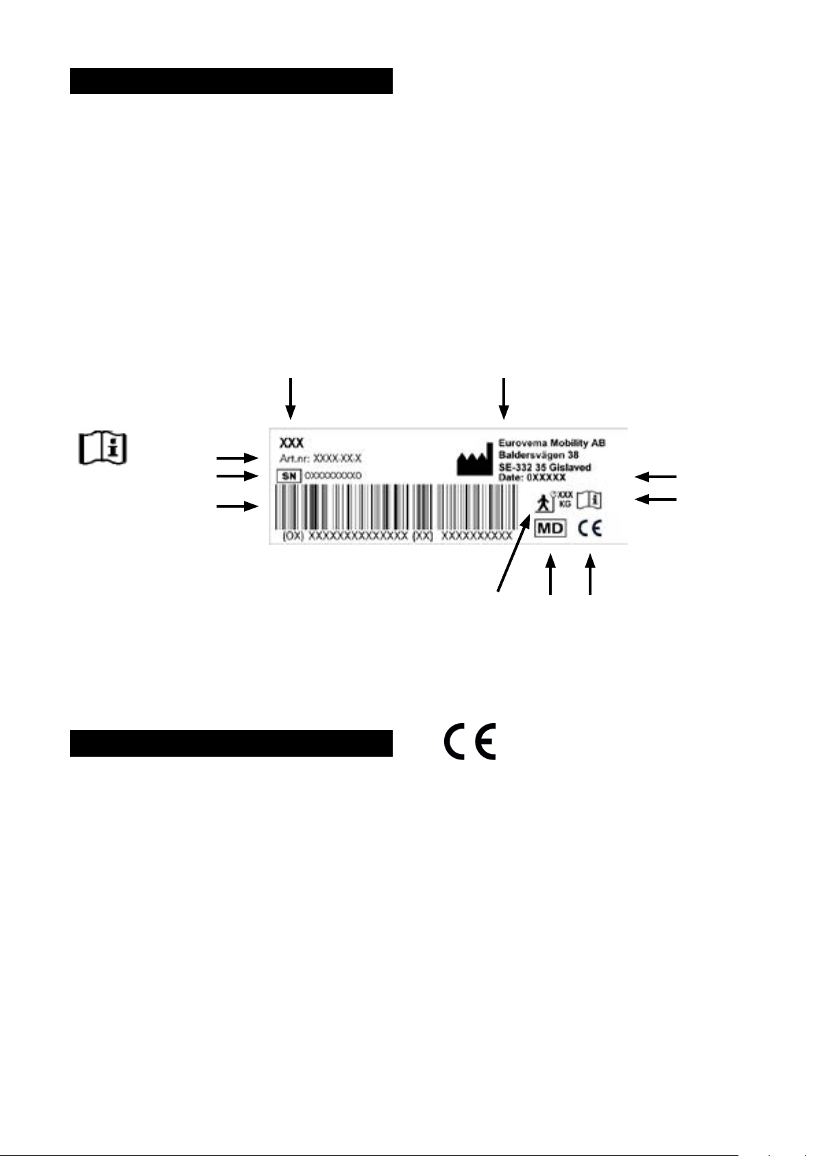
LABEL
All the important technical information can be found on the work chair's label.
1) Product name
2) Part number
3) Serial number (UDI-PI
4) Barcode
5) Max. user weight
6) Medical device
7) CE marking
8) Read the manual before use
9) Manufacturing date
10) Manufacturer’s name
CE MARKING
The product is CE-marked in accordance with the Medical Devices Regulation (MDR 2017/745) of
the European Parliament. The CE mark can be found on the label. The product is compliant with the
requirements of standards EN1335-1, -2, -3, EN60601-1, and EN60601-1-2.

6
OVERVIEW
1) Back support
2) Armrests
3) Seat
4) Height adjustment, seat, Electrical
5) Height adjustment, seat, Gas
a) Under seat
b) Under armrest
6) Width adjustment, armrest
7) Height adjustment, armrest
8) Height adjustment, back support
9) Adjustment of back angle
10) Adjustment of seat depth
7
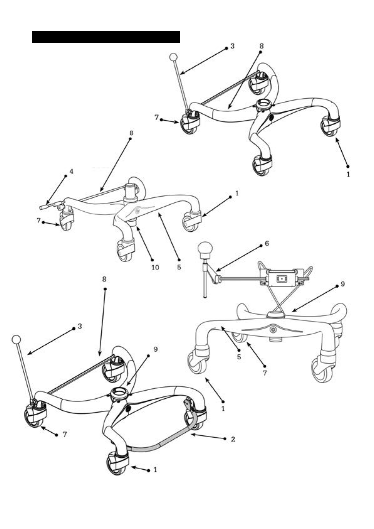
OVERVIEW
1) Front wheel
2) Foot ring
3) Parking, brake lever
4) Parking, foot brake
5) Chassis, exbase
6) Parking Wire exbase
7) Back wheel, braked
8) Brake bar
9) Clamping sleeve for actuator
10) Actuator gas/electrical
8
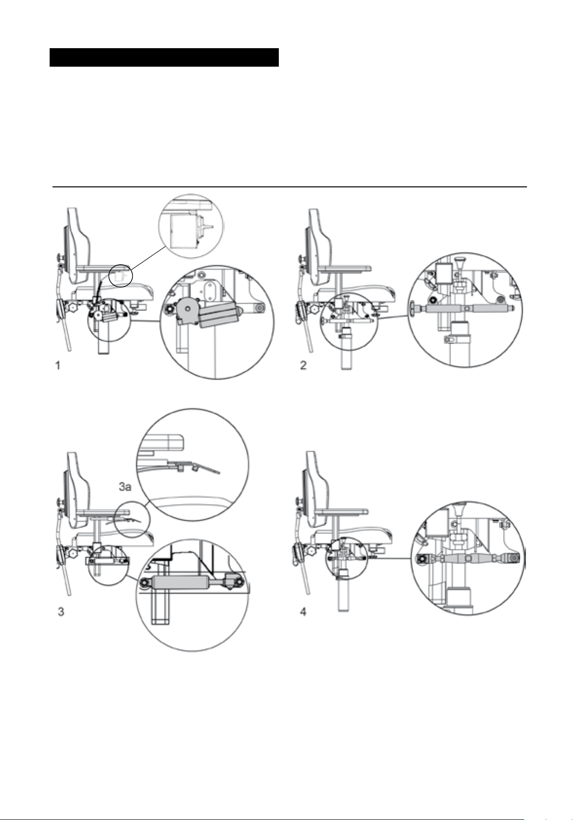
SEAT TILT
The tilt can be adjusted if you have electronic tilt (1), crank (2), gas adjustment (3), or turnbuckle (4).
1) Electronic tilt is controlled via a rocker switch.
2) On chairs with a crank tilt, the seat tilt is adjusted by turning the knob.
3) Gas-controlled tilt. The seat tilt control is located under the armrest. The control lever can be
moved from right to left side. To adjust the seat tilt, press the control up (3a), set to the desired
angle, and release the control.
4) Turnbuckle tilt is adjusted using a spanner (size 17 mm).

9
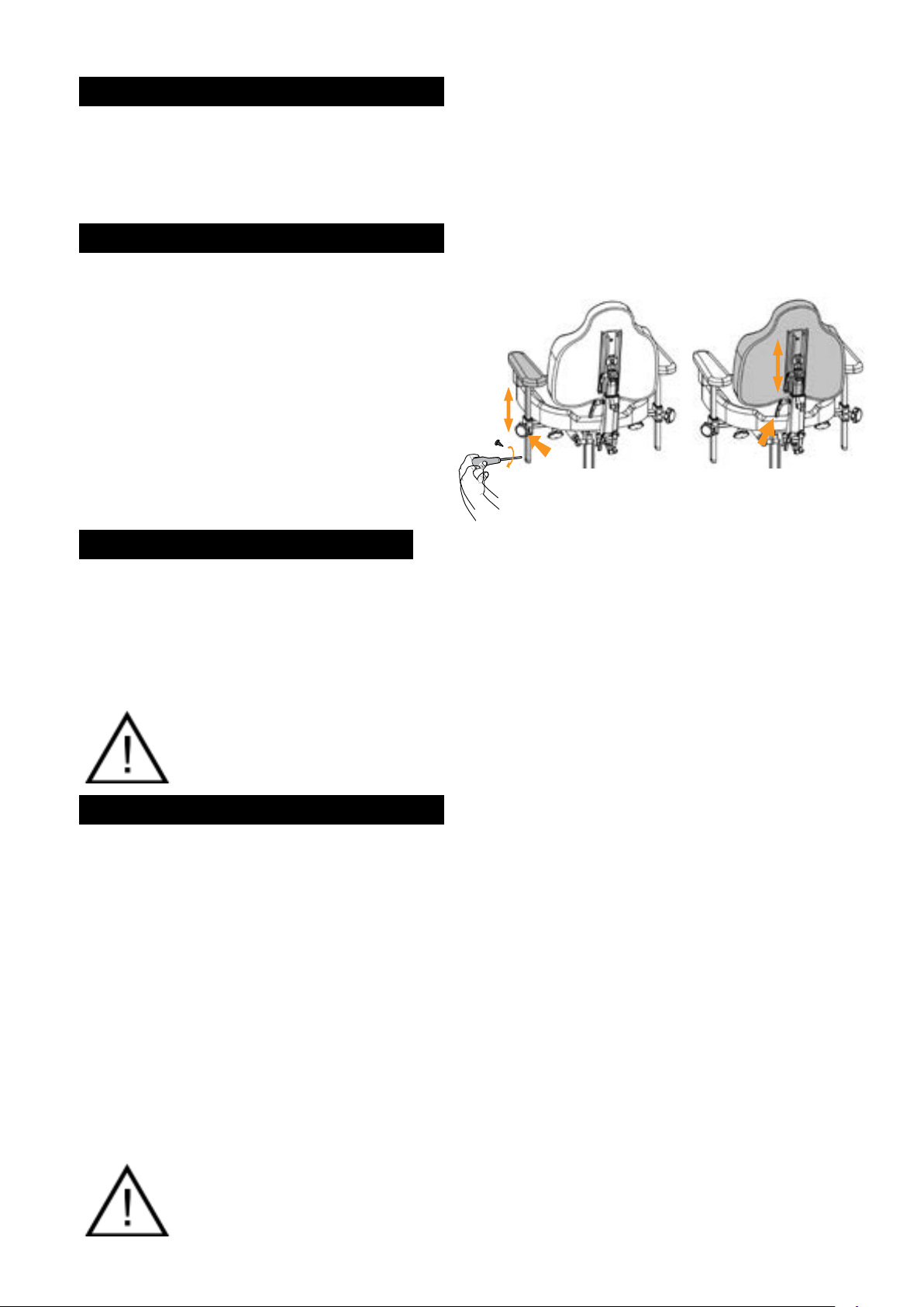
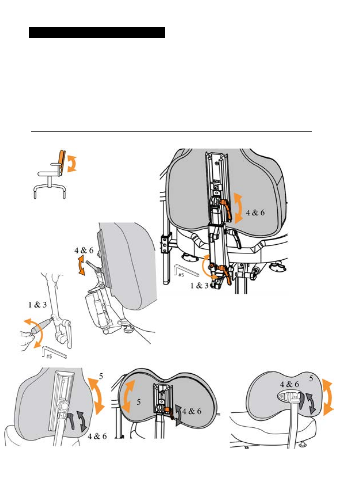
BACK SUPPORT – HEIGHT MULTI-BACK
On the multi-back, you can adjust the height of the back support using both a lever and an adjustment
screw in order to achieve the best level of comfort.
1) Loosen the lever by turning it anticlockwise a ½ turn.
2) Set the desired height on the back support.
3) Lock the lever by turning it clockwise a ½ turn.
4) Loosen the adjustment screw for raising the back on the rail.
5) Set the desired height on the back support.
6) Lock adjustment screw
HEIGHT SETTING OF BACK SUPPORT
Height setting of back support: loosen the
knob. Set desired height. Turn the knob.
Loosen the knob/screw (3).
Set desired height. Tighten the knob/screw.
10
BACK SUPPORT – ANGLE/MULTI-BACK
On the multi-back, you can adjust the back tilt and the back cushion individually in order to achieve
the best level of comfort.
Adjustable back angle
1) Loosen safety screw and lever to angle the whole back mechanism forwards or backwards.
2) Set the desired back angle on the back support.
3) Lock safety screw and lever.
Back rest
4) Loosen the lever by turning it anticlockwise a ½ turn.
5) Set the back support cushion to the desired angle.
6) Lock the lever by turning it clockwise a ½ turn.
ANGLE ADJUSTMENT OF THE BACK
Loosen the knob & adjustment screw (1).
Set desired angle on the back mechanism
(2).
Tighten the knob and the safety screw. (3)
Loosen the knob (4). Set desired angle for the cushion (5). Tighten the
knob/screw (6).
11
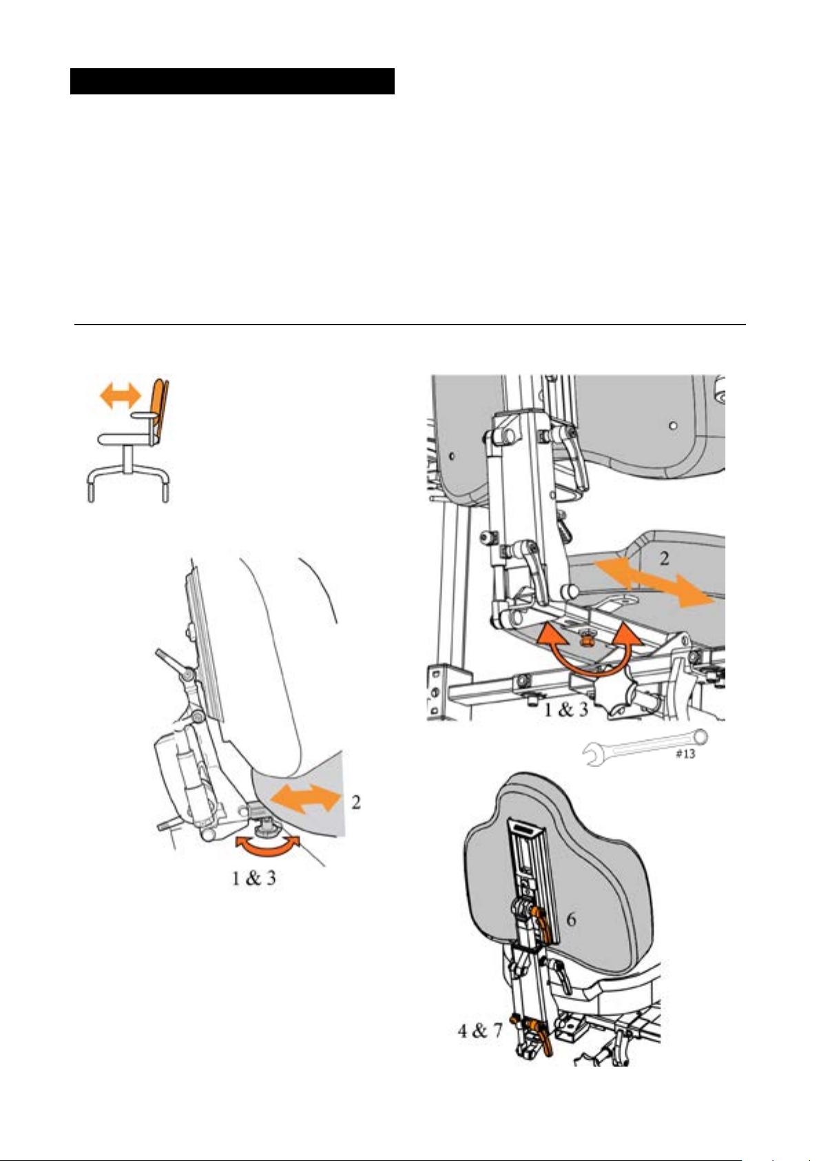
BACK SUPPORT – SEAT DEPTH
The seat depth is adjusted using the back support. Set the desired seat depth by moving the back
support backwards or forwards. Fine tuning of the seat depth can also be done with the help of the
adjustable back angle.
1) Loosen the locking screw/knob under the seat on the rear edge
2) Push the back mechanism in or out to the desired seat depth.
3) Tighten the locking screw/knob beneath.
4) For ne tuning the seat depth, loosen the safety screw and lever for adjusting the back angle.
5) Push the back angle forwards or backwards.
6) Then adjust the angle of the back cushion. Using the lever.
7) Tighten the lever and safety screw on the adjustable back angle.
12
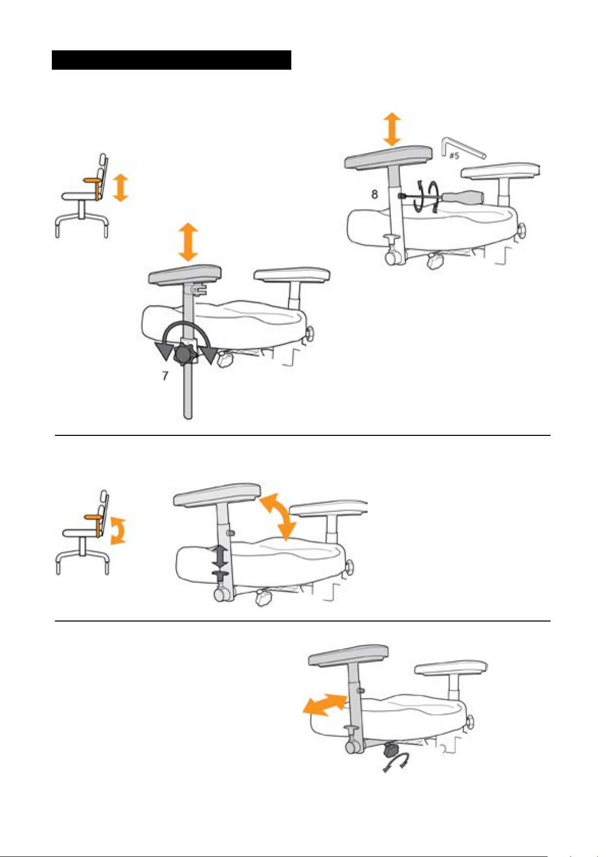
ARMREST – SETTINGS
HEIGHT ADJUSTMENT
Loosen the knob (7) or screw (8) and set the height wanted.
Tighten the knob/screw.
FOLDING ARMREST
Pull the lever up, then angle the armrest backwards.
WIDTH ADJUSTMENT, ARMREST
Turn the wheel and set the desired width.
Tighten the wheel.
13
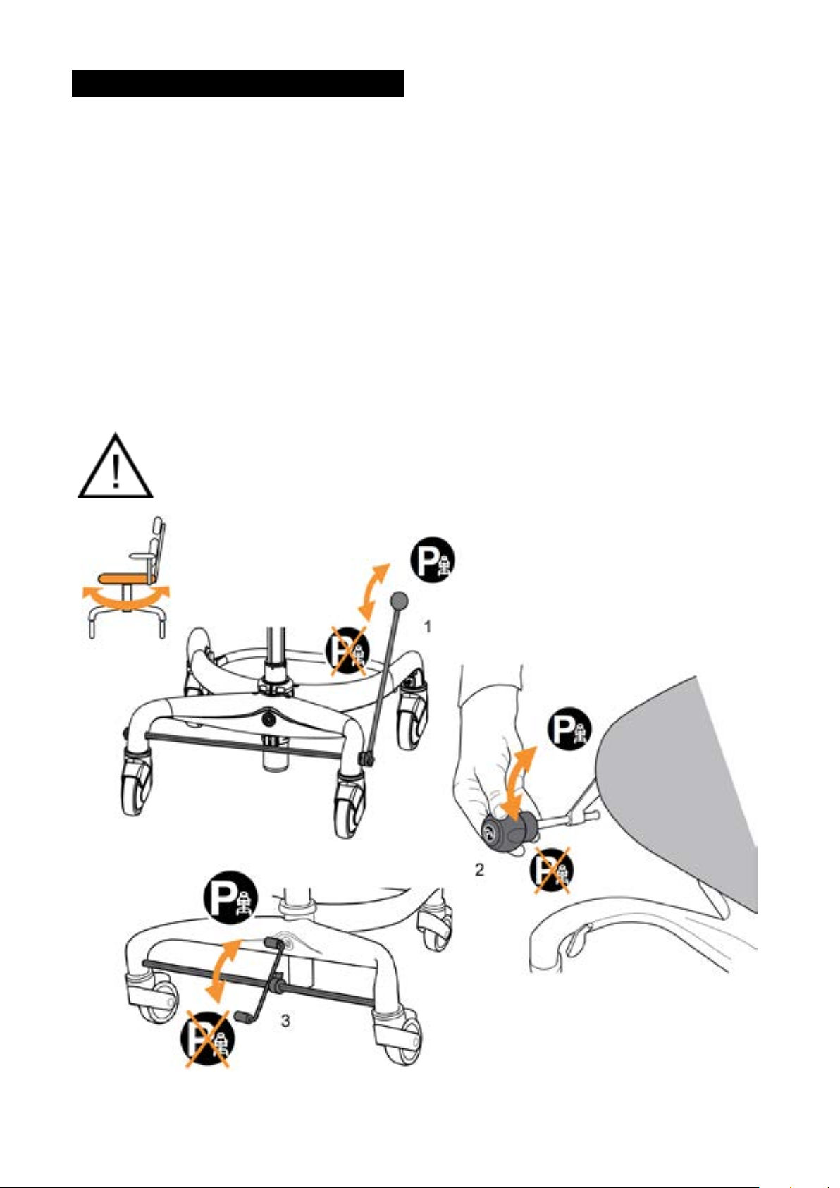
PARKING/BRAKE
1) Lever brake:
Braking: Move the brake lever forwards until you hear a click. The rear wheels are now locked.
Releasing the brake: Move the brake lever backwards until you hear a click. The rear wheels
are now unlocked.
The brake lever can be easily moved from the right to left side with tools. (Allen key no. 5)
2) Wire brake:
The wire brake's movement is reversed.
Braking: Move the lever backwards. Rear or front wheels lock.
Releasing the brake: Move the lever forwards and the stool is unbraked.
3) Foot brake:
Press the front section of the brake pedal down. The rear wheels lock.
Releasing the brake: Press the rear section of the brake pedal down.
If reversed braking is required, you may t the link hoops back-to-front. You then brake by pressing
down on the rear part of the brake pedal, which will lock the rear wheels. Press the front part of the
pedal to release the brakes.
RISK OF INJURY!
NOTE! Always put the chair's brakes on before moving to or from it.
Make sure there are no loose rugs or suchlike lying under the wheels that could
impair the braking.
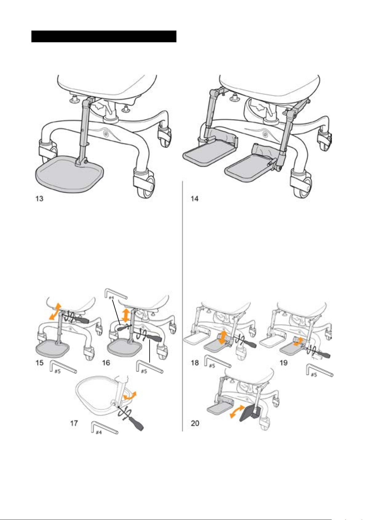
14
FOOTREST
There are two versions of footrest: whole (13) and split (14). Available as accessory.
Settings:
15) leg angle
16) height
17) angle on foot plate up
Settings:
18) height
19) foot angle
20) fold up
15
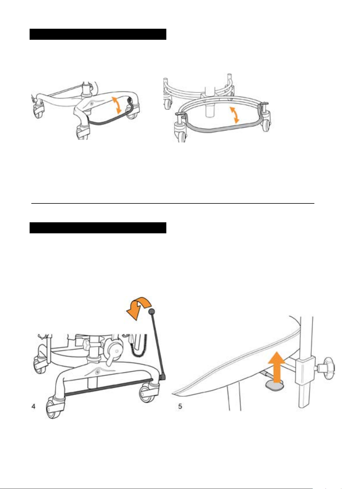
FOOT RING
The foot ring can be folded up, making the chair easier to move.
ROTATION
During rotation, the chair's brakes must be on.
Move the locking lever down (4) to brake the chair.
Move the locking lever (4) upwards to release the brake.
Push the rotation lever (5) upwards, the seat can now be rotated 180 degrees.
The seat can be locked in ve xed positions.
Move the rotation lever downwards to lock in the correct position.
6a 6b
16
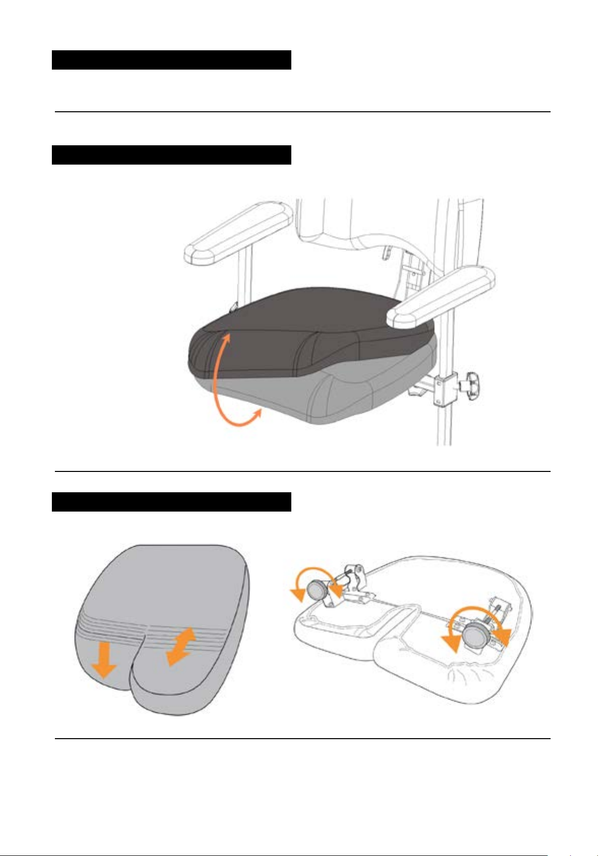
SEAT – ACCESSORIES
COVER
Our covers for both seat and back are easy to remove and put on.
The seat cover is provided with incontinence protection.
Wash according to the washing
instruction on the inside of the
cover.
COXITSITS
Raising and lowering Coxitsits is done individually using adjustment knobs.
17
CHARGING THE BATTERY
To obtain the battery's full performance for as long as possible, it is important to charge it regularly.
Usually, it is sufcient to charge the battery 1-2 times a week, preferable during daytime when the
chair is not in use.
Do not interrupt the charging process before it is nished. Charging can be done in the home without
problem.
If the chair is to be kept in long term storage, the battery should be charged approximately once every
4 weeks to prevent it discharging to the critical level where the charger no longer starts charging.
Do not leave the chair charging for long periods of time.
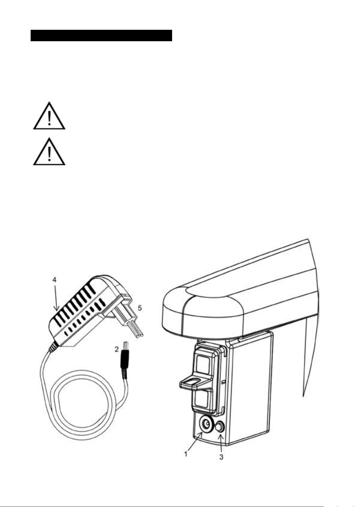
Do not leave the charging plug (2) in the socket (3) once charging is completed.
Important! On seat congurations that feature electric brakes, electric seat tilt
adjustment, and electric back support tilt adjustment, it is particularly important to charge
the batteries on a daily basis in order to ensure that
you can always safely get in and out of the product.
1) The chair needs to be charged when the diode (3) on the control unit is continuously lit when the
chair is not in use. (The LED (3) comes on when electrical function adjustment is in progress.)
2) Connect the charging plug (2) to the socket (3) on the chair. The diode (4) on the front of the wall
plug shines green.
3) Connect the charger's wall plug (5) to a 220 V wall socket. The diode (4) on the front of the wall
plug shines red.
4) When the charging is completed, the diode on the front of the wall plug (4) shines green.
5) Unplug the wall plug (5) rst and then the charging plug (2) from the socket (3).
18
TECHNICAL INFORMATION Work Chair
Work Chair SitRite/Forma/Junior
Data Facts
Class Work Chair – ISO 180903
Weight, electrical 31 kg
Weight, gas 23 kg
User weight 80-140 kg depending on seat system
Battery 24V
ENVIRONMENTAL CONDITIONS Work Chair
Conditions Temperature Humidity Atmospheric pressure
Normal use 10ºC - 40ºC 10% - 90% RH 50 kPa - 106 kPa
Storage & transport -5ºC - 40ºC 10% - 90% RH 50 kPa - 106 kPa
TECHNICAL INFORMATION Chassis
Flexbase
Data Facts
Chassis, width 58 cm
Chassis, length 60 cm
Brake Chassis mounted/seat mounted
Wheel diameter 100 mm
TECHNICAL INFORMATION Electronics
Flexbase
Data Facts
Input voltage 100-240VAC/50-60Hz/ max. 0.35 A
Power consumption 1.0 Amp
Voltage 24 VDC
Electric shock protection Class 1 Equipment
Ingress Protection Code IPX0
Work cycle Intermittent operation MAX 2 minutes ON, 18 Minutes
OFF
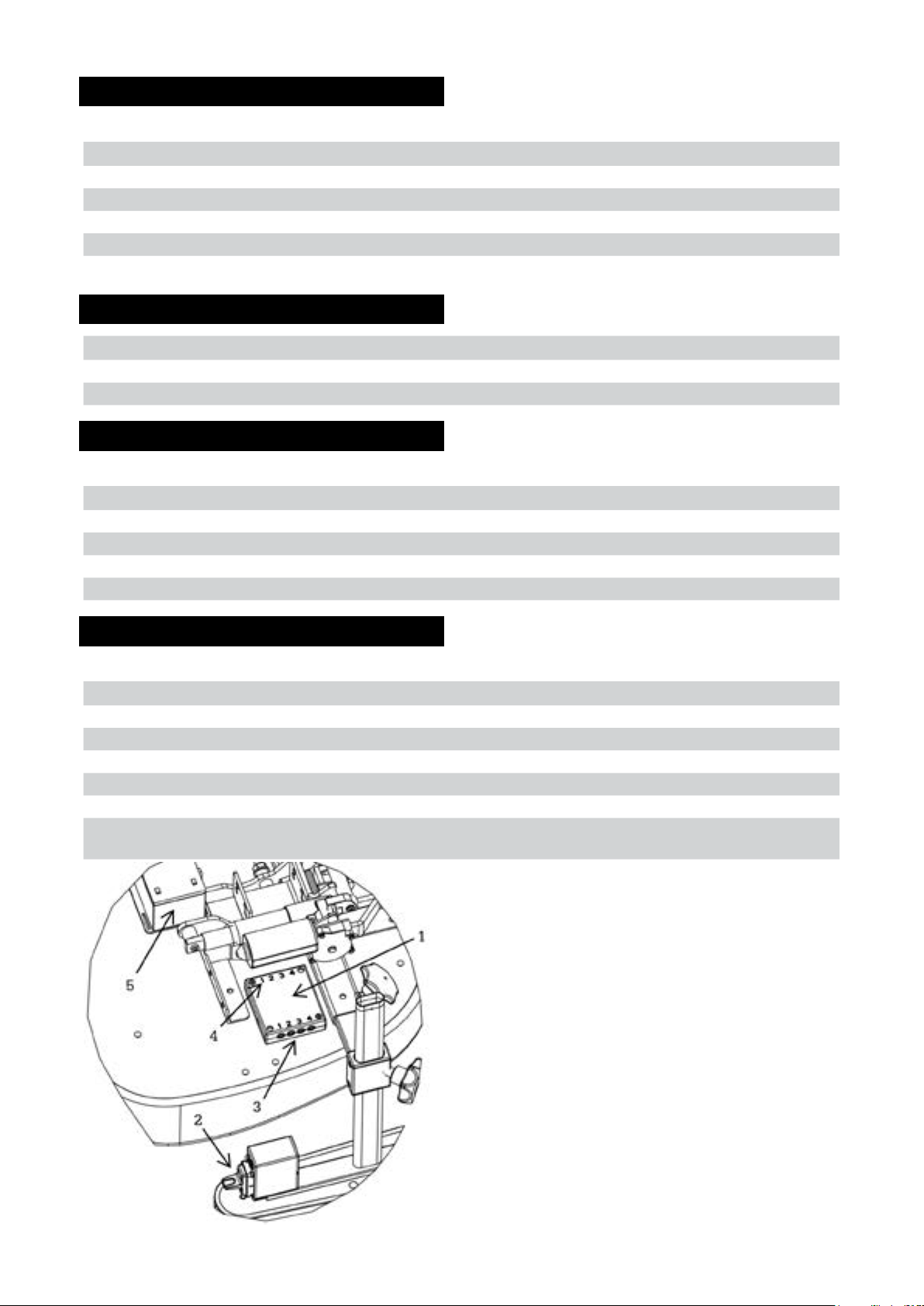
Electronics
1) Main unit
2) Control unit
3) Control unit socket
4) Actuator's socket
5) Battery

19
TECHNICAL INFORMATION Seat
Forma SitRite
Data Facts Facts
Seat (width x depth) 40x40, 40x45,
45x45, 50x50 cm
40x40, 40x45, 45x45
45x50, 50x50 cm
Seat width (between the armrests) 38-56 cm 38-56 cm
Seat depth 40-59cm 40-59cm
Seat height, Gas (height to underneath the
seat)*
37-52, 43-63 cm 37-52, 43-63 cm
Seat height, Electrical (height to
underneath the seat)*
37-55, 43-68 cm 37-55, 43-68 cm
Seat tilt electrical, gas, crank & turnbuckle -22º to 15º -22º to 15º
Back support, height, adjustable* 23-58, 37-62 cm 23-58, 37-62 cm
Back, (width x height)* 37x23, 37x48, 37x46 cm 37x43, 42x45, 47x47 cm
Adjustable back angle 30º 30º
Upholstery Black Atlantic Black Atlantic
Armrest height, Adjustable 0-26 cm 0-26 cm
Armrest, platform 30x8x6 cm 30x8x6 cm
Seat Coxit (width x depth) 45x45, 50x50 cm 45x45, 50x50 cm
Rotation* 180º, Lockable 180º, Lockable
* Varies according to model
***Classic Back, compatible with both models.
SitRite Junior
Data Facts
Seat (width x depth)* 29x32, 32x36, 36x40,
36x45, 40x40, 40x45 cm
**ABC 32x36, 36x40 cm
Seat width (between the armrests) 27-52 cm
Seat depth 32-45 cm
Seat height, gas (height to underneath the seat)* 41-56, 48-68 cm
Seat height, electrical (height to underneath the seat)* 41-58, 45-70 cm
Seat tilt electrical & gas -20º to 12º
Seat tilt crank & turnbuckle -16 to 20º
Back support, height adjustable* 37-54 cm
Back, (width x height)* 30x37, 37x43 cm
Adjustable back angle 30º
Upholstery Black Atlantic
Armrest, height adjustable 0-26 cm
Armrest plate, child 25x8x3
* Depending on model
**A seat other than SitRite

part. no. BRU-80-100. Rev: 201701|8
Other manuals for Euroflex
1
Table of contents
Other Eurovema Indoor Furnishing manuals


Popular Indoor Furnishing manuals by other brands


Costway
Costway JV10197 user manual

Ballard Designs
Ballard Designs Casa Florentina SF017 Assembly instructions

Next
Next 788685 Assembly instructions

Forte
Forte JPTS84T Assembling Instruction

Graham Studios
Graham Studios 6R-RD instruction manual

Garden Trading
Garden Trading Talland TLPC01 Assembly instructions