EV Global Motors E-Bike 24V User manual

MANUAL
24V MODELS
SERVICE

E-Bike™
Service Manual
24V MODELS
EV Global Motors Company
10900 Wilshire Boulevard
Suite 310
Los Angeles, CA 90024
Tel: 310/208-7076
Fax: 310/208-2444
www.ebike.com

Copyright © 2000 EV Global Motors Company
Second Edition
September, 2000
LIT-82001-00-00
All rights reserved. No parts of this publication may be
reproduced or transmitted in any form or by any means
without the prior permission of EV Global Motors
Company.
Although every precaution has been taken to assure this
publication is complete and accurate, EV Global
assumes no liability for errors or omissions. All informa-
tion contained in this publication is based on the latest
information available at the time of publication and is sub-
ject to change without notice.

TABLE OF CONTENTS
Chapter One: General Information 1-1
Beep/LED Codes
Terms
Vehicle Identification Number
Key number
Model Code
How to Read the Model Code
Terms
Lubricants
Threadlock
Recommended Maintenance Schedule
Special Tools
Chapter Two: Specifications 2-1
Mechanical Specifications
Gear Ratios
Electrical Specifications
Torque Specifications
Performance Specifications
Frame Specifications
Chapter Three:Battery Pack 3-1
Charging the Batteries
Replacing the Batteries
Replacing the Charger
Battery Pack
Chapter Four: Handlebar and Controls 4-1
Handlebar Position
Handlebar Height Adjustment
Handlebar Replacement
Throttle Control-Housing
Accessory Control Housing
Headset
Chapter Five: Brakes 5-1
Brake Cable Replacement
Brake Lever
Brake Lever Free Play Adjustment
Brake Pad
Brake Pad Alignment
Caliper Arm
Disc Brake
Chapter Six: Shifter and Derailleur 6-1
Shifter
Shifter Cable
Derailleur
Chapter Seven: Chain and Crankset 7-1
Chain
Crank Arm
Chainring
Pedal
Bottom-Bracket Cartridge
Chapter Eight: Electrical 8-1
Connector Identification
Right Side Cover
Left Side Cover
Controller
Quick-Release Connector
Motor
Headlight
Taillight
Troubleshooting
Electrical Schematic

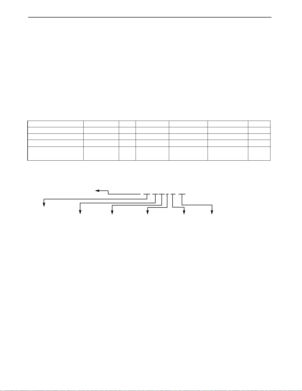
BEEP/LED CODES
The E-Bike™ beeps and flashes various codes to alert the rider to particular conditions. The fol-
lowing chart lists the codes and describes their various functions. Beep codes consist of a series of
long and short beeps, like Morse code.A long beep is represented by a dash (-).A short beep is rep-
resented by a dot (•).
Code Meaning Beep LEDs
OK The battery pack is - - - - •-
installed and properly
connected.
GO Sounds at power knob ON. - - •- - - The charge level
The system is on and LEDs cycle twice
ready to operate. in sequence.
Pedal assist The system requests •- - •
pedal assist. Sounds
when on a steep hill
or when the motor has
overheated.
Over heat 1 The motor is - - - ••••
overheated. Followed by the pedal
The system will disable the assist code (•- - •)
motor within 3-5 every 8 seconds
seconds.
Over heat 2 Sounds at power knob ON - - - - •-
if the motor has been
disabled.
System refusal An error has been - •- - -
detected.The system
will not operate.
Battery state of Indicates the battery Green = 100-60%
charge state of charge within 3 Yellow = 60-20%
seconds of power knob ON. Red = 20-0%
Low battery The system will shut •- ••- - - Charge level
LEDs
down within 3 to 5
cycle continuous
ly
seconds. in sequence.
1-1
Chapter One
GENERAL
INFORMATION
KEY NUMBER
The 4-digit key number is stamped on the
upper portion of the key shaft.
MODEL CODE
HOW TO READ THE MODEL CODE
ModelYear 99 B1 24 C V 00 BK
Product Line
& Category Power System Model Brake Type Battery Type Color
B1 = Bicycle, 24 = 24 Volts Base = B V=V-brake 00=Lead-Acid ML=Metallic Blue
Conventional Comfort = C D=Disk brake CR = Metallic Cranberry Red
Touring = T BK = Black
RD = Rally Red
1-2
Model code Model prefix Year Description Color 1 Color 2 Color 3
B1 Bicycles
99-B124BV00-BK,RD 1B1 1999 Base Black (BK) Rally Red (RD) NA
99-B124CV00-BK,RD 2B1 1999 Comfort Black (BK) Rally Red (RD) NA
99-B124TV00-ML,CR 2B1 1999 Touring Metallic Metallic NA
Blue (ML) Cranberry (CR)
TERMS
Left and Right
Most of the time, left and right in this man-
ual refer to the rider’s point of view when seat-
ed on the E-Bike™ and facing forward. The
one exception to this rule involves the brake
calipers. Left and right on the calipers refers to
a technician’s point of view when standing in
front of the E-Bike™ and looking directly at the
front brake caliper or when standing behind the
E-Bike™ and looking directly at the rear brake
caliper.
NOTE, CAUTION and WARNING
The terms NOTE, CAUTION and WARN-
ING have specific meaning in this manual. A
NOTE provides additional information to make
a procedure easier or clearer.
A CAUTION emphasizes precautions that
must be taken to avoid damage to your tools or
to the E-Bike™.
A WARNING alerts you to a situation where
negligence could lead to injury or death. Take
WARNINGS seriously. Failure to heed a
WARNING could result in serious personal
injury or death.
VEHICLE IDENTIFICATION NUMBER
The 17-digit vehicle identification number
(VIN) is printed on a label that is affixed to
the inside face of the right frame seat stay.
This label also contains the gross-vehicle
weight rating and recommended tire inflation
pressure.

LUBRICANTS
Grease
The bearings and other mechanical com-
ponents in the E-Bike™ operate at relatively
low temperatures so most automotive greases
are inappropriate for use on the E-Bike™.
Always use grease made specifically for a
bicycle, such as grease from Bullshot,
Campagnolo, Finish Line, Pedros, Phil Wood,
and Shimano.
OilAlways use oils made specifically for bicy-
cle use. Bicycle oils need to be thin enough to
penetrate tight places, they should be durable
so they can withstand exposure to the ele-
ments, and they must resist the accumulation
of dirt.
Suitable oils for the E-bike include Alsop,
Bullshot, Campagnolo, Finish Line, Lube Wax,
Phil Wood Tenacous Oil, Pedros, Superlube,
and Triflow.
Motor oil, WD40, 3-in-1 Oil, sewing
machine oil, gun oil, and other common oils
are not suitable and should not be used.
In general, applying oil from a drip applica-
promote over-lubrication, which leads to
excessive accumulation of dirt. Apply oil spar-
ingly. Apply enough oil to do the job, but not so
much that it starts to drip from the component.
After applying any oil, wipe off the excess.
THREADLOCK
A threadlocking compound should be used
on most fasteners on the E-Bike™.
Threadlocking compound prevents loosening
caused by vibration and helps seal out mois-
ture.
Loctite 242 (blue) or equivalent is recom-
mended for threadlocking applications. Loctite
242 is a medium-strength threadlocking com-
pound that permits disassembly with common
hand tools.
Before applying Loctite to threads, clean
the thread surface of oil, grease, and other
residue. Apply a small amount of Loctite.
Excess compound could work its way down
the threads and bond parts together. The
torque chart in Chapter Two includes Loctite
recommendations for particular fasteners.
1-3
RECOMMENDED MAINTENANCE SCHEDULE
Component or Condition Inspect before every ride Inspect every 5 to 10 rides*
Brake pad adjustment X
Wheel quick release adjustment X
Tire pressure X
Tire wear/damage X
Head/tail/brake light operation X
Mirror position X
Controls and display X
Seat post quick release adjustment X
Brake pad wear X
Brake cable tension/wear XX
Spoke tension X
Wheel true X
Hub bearings adjustment X
Hub bearing lubrication X
Chain lubrication X
Derailleur adjustment X
Reflectors X
Battery and charger X
Headset adjustment X
Bottom bracket adjustment X
Tighten all bolts, nuts, and mounting X
hardware
* Depending upon length of ride and riding conditions. Inspect more frequently when riding in dusty or wet
conditions.

SPECIAL TOOLS
The following special tools are needed for servicing the E-Bike™.
Tool Part number
Hex wrench set: 4mm, 5mm, 6mm Park AWS-1
Hex wrench set Park AWS-11C
Hex wrench set: 2mm, 5mm, 3mm Park AWS-3
Fourth hand cable stretcher Park BT-2
Chain checker Park CC-2C
Chain breaker (screw type) Park CT-3
Crank wrench Park CCW-14R
Cable and housing cutter Park CN-4C
Gearclean brush Park GSC-1
32mm & 36mm head wrench Park HCW-15
Pedal wrench Park PW-3
Spoke wrench (black) Park SW-0
Spoke wrench (red) Park SW-2
Tire lever set Park TL-1C
Freewheel tool Park Tool FR-1
Bottom-bracket-cartridge tool Park Tool BBT-2
1-4

Table 1: Mechanical Specifications
Component Specification
Headset
Stack height 33 mm (1.30 in.)
Dimensions 25.4 mm x 34 mm x 30 mm w/seal
Fork
Type PU Allen key adjustable
Steerer tube 1-1/8 in.
Travel 65 mm
Stem 1
Std. model 17 degrees, 110 mm extension
C & T models 40 degrees, 110 mm extension
Stem 2 28.6 mm x 25.4 mm x 150 mm with quill
Handlebar
Std model
Rise 30 mm, 10 degrees
Width 620 mm
Handle 200 mm
Seat post
Std model 300 mm x 30.0 mm O.D.
Seat post spacer 100 mm x 30.1 mm ID x 34.9 mm O.D.
Seat post, suspension
C & T models 350 mm x 27.2 mm O.D.
Seat post spacer 100 mm x 27.3 I.D. x 34.9 mm O.D.
Tires
Std & C models 26 x 1.95 in., black
T model 26 x 1.95 in., Skinwall black
Rims 26 x 1.5 in., 14G x 36H, double wall
Spokes
Front 266 mm, 14G stainless with brass nipples
Rear 216 mm & 219 mm, 14G stainless with brass nipples
Bottom bracket (B/B) 127 mm cartridge
Freewheel 14-28 T, 7-speed
Chainring 33 T
Chainring clearance 16~17 mm (0.63~0.67 in.)
Crankarm 170 mm (6.7 in.)
Chain 1/2 x 3/32 x 110 L
2-1
Chapter Two
SPECIFICATIONS

Table 2: Gear Ratios
Chainring Freewheel Gear Inches Ratio
33T 14T 61.3 0.42 (14/33)
33T 16T 53.6 0.48 (16/33)
33T 18T 47.7 0.55 (18/33)
33T 20T 42.9 0.61 (20/33)
33T 22T 39.0 0.67 (22/33)
33T 24T 35.8 0.73 (24/33)
33T 28T 30.6 0.85 (28/33)
Table 3: Electrical Specifications
Component Specification
Battery (WP12-12) 2 in series
Type Deep discharge, sealed AGM lead-acid
Capacity 12 volts, 12 amp hours.
Charger
Input 115 VAC, 60/50 Hz, 2 amps
Output 24 VDC, 3 amps
Charger cord
Length 1.2 m (4 ft.)
Wire 18 AWG, 2-wire with ground
Chapter Two
2-2

Table 4:Torque Specifications
Item kg-cm in.-lb. ft.-lb. Special Instructions
Handlebar-binder bolt 140~200 - 10~15 Apply Loctite
Handlebar-arm clamp bolts 140~200 - 10~15 Apply Loctite
Stem-binder bolt (stem-2 quill bolt) 180~250 - 13~18
Headset locknut 40~50 34.7~43.4
Accessory control clamp bolt 30~40 26.5~34.7 -
Throttle-control clamp bolt 30~40 26.5~34.7 -
Controller mounting screw 15 13.0 -
Brake-lever clamp bolt 30~40 26.5~34.7 -
Brake-caliper pinch bolt 140~200 - 10~15 Apply Loctite
Brake-pad nut 63.6~85.2 53~71 -
Caliper pivot bolt 85.2~106.8 71~89 - Apply Loctite
Left-side-cover mounting screws 10 8.6 - Apply Loctite
Right-side-cover mounting screws 10 8.6 - Apply Loctite
Battery-terminal-block mounting screw 10 8.3 -
Battery compartment mounting screw 10 8.3 -
Battery pack handle 15 13.0 -
Battery cover screw 20~30 17.4~26.5 Apply Loctite
Charger-board mounting screw 10 8.6 -
Derailleur mounting bolt 84 70 -
Derailleur pinch-mechanism nut 42 36.5 -
Shifter clamp bolt 30~40 26.5~34.7 -
Mirror-mounting screw 30~40 26.5~34.7 -
Chain guard screws 15 13.0 - Apply Loctite
Left bottom-bracket cover screws 20~30 17.4~26.5 - Apply Loctite
Crank-arm mounting bolt 200~250 - 14.4~18.1 Apply grease to the bolt
threads
Pedal 30~50 26.5~43.4 - Apply grease to the stud
threads
Bottom-bracket cartridge adapter ring 300~400 - 21.7~28.9 Apply grease to the threads
Chainring bolt 350~450 - 25~32 Apply oil to the bolt threads
Motor torque arm 15 13.0 - Apply Loctite
Headlight mount 15 13.0 -
Taillight mounting nut 20 17.4
Horn mounting nut 15 13.0 -
Cord access cover 5 4.2 -
Frame mounted connector 10 8.6 - Apply Loctite
Front fender 15 13.0 -
Rear fender 15 13.0 -
SPECIFICATIONS 2-3
Table 5: Performance Specifications*
Item Specification
Top speed 13.5-14.0 mph
Range (E mode, flat, no wind) 18-20 miles
Maximum gradeability 11% grade, 6 mph
Acceleration 0-10 mph in 5.3 seconds
*200-pound rider with tires inflated to 60 psi.

Frame Specifications
Frame Size (Center to top)
419 cm (16.5 in.)
Wheel Base 1062.3 mm (41.8 in.)
RC 431.5 mm
(17.0 in.)
72˚
Head Tube
163 mm (6.4 in.)
2-4

CHARGING THE BATTERIES
The E-Bike™ includes a charger that is an
integral part of the battery pack. Batteries can
be charged when the battery pack is on-board
the E-bike™ or when the battery pack is
removed for remote charging.
To assure maximum battery life, always
fully recharge the battery after each ride. If the
E-Bike™ will not be used for more than one
week, remove the battery pack from the E-
Bike™ and store it in a cool, dry place. The
controller uses a small amount of power when-
ever the battery pack is installed in the E-
Bike™. Consequently, the batteries slowly dis-
charge whenever the battery pack is in place,
even if the power knob is OFF.To prevent total
battery discharge during extended periods of
non-use, remove the battery pack and store it
in a cool, dry place. A stored battery should be
recharged at least every three months to help
maintain performance and quality.
On-board Charging
1. Be sure the power knob is turned OFF.
2. Turn the battery-compartment latches
clockwise, and open the door.
3. Retrieve the charging cord from the com-
partment above the bottom bracket.
4. Plug the female end of the charging cord
into the receptacle on the battery
charger.(Figure 1)
FIG.1
Chapter Three
BATTERY PACK
3-1
WARNING
The charger is equipped with a cooling fan. If
the cooling fan does not operate when the
charging cord is plugged in and the red LED is
on, unplug the charger from the electrical out-
let immediately. Determine why the fan is not
operating before charging the battery pack.
Replace the charger if necessary.
5. Plug the male end of the charging cord into
a standard 110V/60 cycle electrical outlet.The
red LED on the charger and the cooling fan will
automatically turn on. The LED switches to
green and the cooling fan turns off when the
battery pack is fully charged.
Remote Charging
1. Remove the battery pack from the E-Bike™.
2. Set the battery pack on its side so the bat-
tery-pack cover faces up and the handle is to
the side.
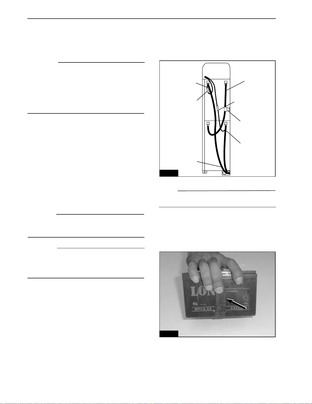
FIG.3
Chapter Three
3. Retrieve the charging cord from the com-
partment above the bottom bracket.
4. Plug the female end of the charging cord
into the receptacle on the battery charger.
WARNING
The charger is equipped with a cooling fan. If
the cooling fan does not operate when the
charging cord is plugged in and the red LED is
on, unplug the charger from the electrical out-
let immediately. Determine why the fan is not
operating before charging the battery pack.
Replace the charger if necessary.
5. Plug the male end of the charging cord into
a standard 110V/60 cycle electrical outlet.The
red LED on the charger and the cooling fan will
automatically turn on. The LED switches to
green and the cooling fan turns off when the
battery pack is fully charged.
REPLACING THE BATTERIES
The battery pack contains two sealed lead-
acid batteries that are connected in series.The
following procedure describes how to remove
and replace the two batteries.
CAUTION
Always replace both batteries as a set. Do not
mix old batteries with new batteries, and do not
mix different brands of batteries.
WARNING
Never use a battery that is cracked or broken.
Battery acid is highly corrosive and can cause
severe burns if it comes in contact with your
eyes or skin.
Removal
1. Remove the battery pack from the E-Bike™.
2. Remove the two cover screws from the bat-
tery pack, and remove the cover.
3. Disconnect and remove the blue intercon-
nect wire that connects the two batteries to
each other in series.Note the fuse on the inter-
connect cable (Figure 2).
4. Disconnect the battery-pack leads (black
and red) from the spade connectors on each
battery.
3-2
FIG. 2
Black
Black
Interconnect Wire
(Blue)
Red
Fuse
Bullet Connector Bullet Connector
5. Invert the battery case.Tap the case against
the bench or floor to dislodge the batteries
from the battery pack.
6. Remove each battery and its damper strap
(Figure 3).
NOTE
Contact your state or local agency for informa-
tion on proper battery disposal.
7. Properly dispose of the old batteries.
Installation
1. Wrap the damper strap around the first bat-
tery (Figure 3).
2. Set the battery into the compartment so the
end with the spade connectors faces the
charger. Press the battery into the compart-
ment until it bottoms.

Installation
1. Be sure the insulator (B, Figure 6) is in
place in the battery pack.
2. If removed, install the spacer (A, Figure 6)
onto each mounting stud in the battery pack.
3. Set the charger board into place on the
mounting studs.Secure the board in place with
the charger-board mounting screws and wash-
er (Figure 5).
4. Secure the board to the bracket with the
mounting screw (B, Figure 4).
5. Plug the connectors from the cover into
their mates in the charger board.
6. Fit the cover in place over the charger
board. Be sure the two charger wires are not
pinched under the cover.
7. Secure the cover in place with the three
charger-cover screws (A, Figure 4).
8. Reinstall the batteries and the battery-pack
cover.
3. Repeat for the second battery.
4. Inspect the fuse on the blue interconnect
wire. Replace the fuse as necessary.
5. Connect the blue interconnect wire to the
upper battery’s positive terminal and to the
lower battery’s negative terminal.
6. Connect the red lead from the battery pack
to the positive terminal on the lower battery.
7. Connect the black lead from the battery
pack to the negative terminal on the upper bat-
tery.
8. Fit the cover onto the battery pack. Be sure
no wire is pinched beneath the cover.
9. Apply Loctite 242 (blue) to the threads of
the two cover screws, and secure the cover in
place.
REPLACING THE CHARGER
Removal
WARNING
Make sure the charger is not plugged in during
service.
1. Remove the batteries from the battery pack.
2. Remove the three charger-cover screws
that secure the cover to the vent (A, Figure 4).
3. Lift the cover from the charger, and discon-
nect the three electrical connectors from the
charger board.
4. Remove the screw that secures the charg-
er board to the bracket (B, Figure 4).
5. Remove the three charger-board mounting
screws (Figure 5), and remove the charger
board. Do not lose the spacer (A, Figure 6)
from each mounting stud.
FIG.4
FIG. 6
FIG. 5
3-3
A
A
A
AA
A
B
B

BATTERY PACK
Removal
1. Turn the power knob OFF.
2. Open the battery compartment door.
3. Release the gate latch, and open the bat-
tery gate.
4. Use the handle to pull the battery pack from
the compartment. Be sure to support the bot-
tom of the battery pack with your free hand.
Installation
1. Set the lower end of the battery pack into
the battery compartment, and tilt the battery
into place.
NOTE
The E-Bike™ beeps the OK (_ _ _ _•_) when-
ever the battery pack is reinstalled and good
contact exists between the battery pack and
terminal block in the E-Bike™.
2. Close the gate over the battery, and secure
the gate latch.
3. Close the battery compartment door, and
turn the latches counterclockwise.
BATTERY PACK TEST
Charger operation test
1.Plug the female end of the charging cord into
the port on the charger.
2. Plug the male end into a 110-volt outlet.
3.Watch the battery charger LED and perform
the indicated procedure.
a. If the battery charger LED does not illu-
minate, the charger is faulty and should
be replaced. Unplug the charging cord,
and check the battery voltage (before
charging) as described below.
b. If the battery charger LED turns to
red and the cooling fan is not operating,
the charger is faulty and should be
replaced. Unplug the charger, and
check the battery voltage (before charg
ing) as described below.
c. If the battery charger LED turns red and
the cooling fan operates, perform the
charger output test described below.
d. If the battery charger LED turns green,
perform the charger output test
described below.
Charger Output Test
1. Remove the cover from the battery pack.
2. Connect a voltmeter’s positive (+) test probe
to the positive (+) battery terminal, and con-
nect the voltmeter’s negative (-) test probe to
the battery negative terminal as shown in
Figure 7. Note the reading on the voltmeter.
3. With the voltmeter still connected as
described in step 2, plug the charger into a
110-volt outlet. Note the reading on the volt-
meter.
4. Compare the two readings.
a. If the reading is higher when the charger
is plugged in, the charger is operating
properly. Perform the battery voltage
test (before charging).
b. If the two readings are the same, the
charger has failed and should be
replaced.
Battery Voltage Test, Before Charging
1. Let the battery stand for one hour.
2. Remove the cover from the battery pack.
3. Connect a voltmeter’s positive (+) test probe
to the positive (+) battery terminal, and con-
nect the voltmeter’s negative (-) test probe to
the battery negative terminal as shown in
Figure 7.
4. Note the reading on the voltmeter.
5. If the reading is less than 12 volts, the bat-
tery is faulty and should be replaced.
3-4

Battery Voltage Test, After Charging
NOTE
The charger must be operational for this test to
be valid.Perform the charger output test before
performing this test.
1. Charge the battery as described in this
chapter.
2. Unplug the charger, and let the battery
stand for one hour.
3. Remove the cover from the battery pack.
4. Connect a voltmeter’s positive (+) test
probe to the positive (+) battery terminal, and
connect the voltmeter’s negative (-) test probe
to the battery negative terminal as shown in
Figure 7.
5. Note the reading on the voltmeter.
6.The reading should be 12.5 volts or greater.
If the reading is less than 12.5 volts, the bat-
tery is faulty and should be replaced.
3-5
FIG. 7
HANDLEBAR POSITION
NOTE
The handlebar may be adjusted to suit the
rider’s preference. The following procedure
describes how to set the handlebar to the stock
position.
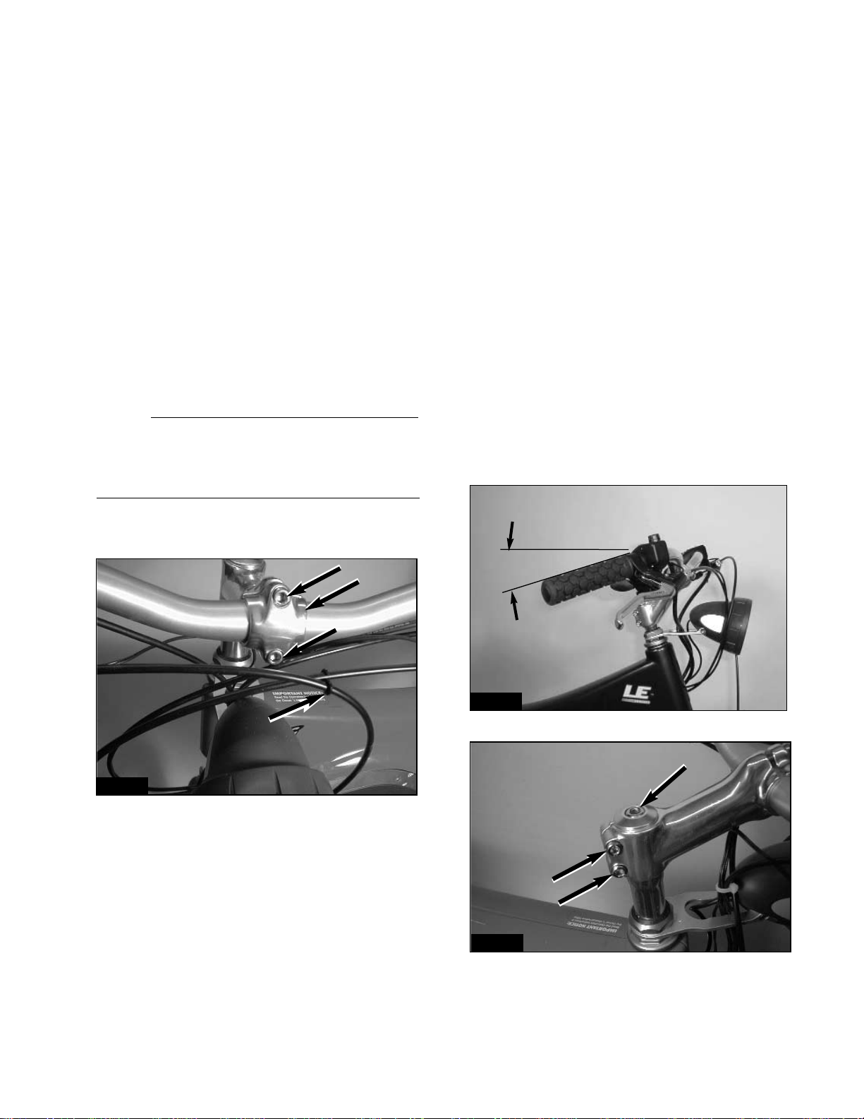
1. Loosen the handlebar-binder bolts (A,
Figure 1).
2. Position the handlebar so the ends point
down slightly.The handlebar grips should form
a 10-20˚ angle with a line that parallels the
floor. See Figure 2.
3.Be sure the knurled portion of the handlebar
is centered within the handlebar binder.
4. Tighten the handlebar-binder bolts to the
torque specification in Table 4.
HANDLEBAR HEIGHT ADJUSTMENT
1. Loosen the stem-binder bolt three or four
turns counterclockwise (A, Figure 3).If the bolt
rises from the steering stem, strike the bolt with
a plastic mallet to force the stem wedge down.
FIG.1
FIG. 2
FIG. 3
4-1
Chapter Four
HANDLEBAR
and CONTROLS
A
BA
B
C
B
A10~20˚

CAUTION
The "Minimum Insert" mark on the handlebar
stem must not sit above the top of the headset.
2. Raise or lower the stem within the head
tube until the handlebar is at the desired
height.
3. Rotate the handlebar from side to side, and
align the handlebar with the wheel or fork
dropouts.
4. Tighten the stem-binder bolt to the torque
specification in Table 4.
HANDLEBAR REPLACEMENT
Removal
1. Note how the brake cables, shifter cable,
and electrical wires are routed around the
headlight. They will have to be rerouted along
the same path during installation.
2. Remove the following components from the
right handlebar:
a.The handlebar grip.
b. The brake-lever housing
c.The throttle control and throttle stop.
3. Remove the following from the left handlebar:
a.The mirror.
b. The handlebar grip
c.The shifter.
d.The brake-lever housing.
e.The accessory control.
4. Remove the two handlebar-binder bolts (A,
Figure 1).
5. Remove the handlebar clamp (B, Figure 1)
and the handlebar.
Installation
1. Fit the handlebar into place in the binder on
the handlebar arm.Be sure the knurled portion
of the handlebar is centered in the binder.
2. Fit the handlebar clamp into place around
the handlebar.
3. Apply Loctite 242 (blue) to the threads of
the handlebar-binder bolts, and install the bolts
finger tight.
4. Position the handlebar as described in this
chapter, and tighten the handlebar-binder bolts
to the torque specification in Table 4.
5. Install the throttle control as described in
this chapter.
6. Install the accessory control as described
in this chapter.
THROTTLE CONTROL (RIGHT SIDE)
Removal
1. Remove the battery from the battery com-
partment.
2. Remove the right side cover from the E-
Bike™.
3. Pull the cable inlet cover around the head
tube, and remove the cable inlet cover from the
left side cover.
4. Disconnect the throttle control connector (F,
Figure 4) from the controller board. Note how
the throttle control wire is routed through the
frame. The new wire will have to be rerouted
along the same path.
5. Pull the wire so the connector passes
through the frame and emerges at the cable
inlet in the left side cover (Figure 5).
C
LM
N
Yellow
DEF
J
I
H
G
K
Behind controller connectors AB
Horn board
Controller board
Red
Black
FIG. 4
FIG. 5
Chapter Four
4-2
Behind controller connectors
Horn board
Controller board
6. Twist and remove the right handlebar grip
from the handlebar.
7. Disconnect the front brake cable from the
S-hook (C, Figure 1).Note how the front brake
cable is routed around the headlight. It will
have to be routed along the same path during
assembly.
8. Loosen the right-brake-lever clamp bolt,
and slide the brake lever body from the right
handlebar. Guide the front brake cable around
the headlight as you remove the brake lever.
9. Lay the brake lever over the frame top tube
so it is out of the way. Do not severely bend or
kink the cable.
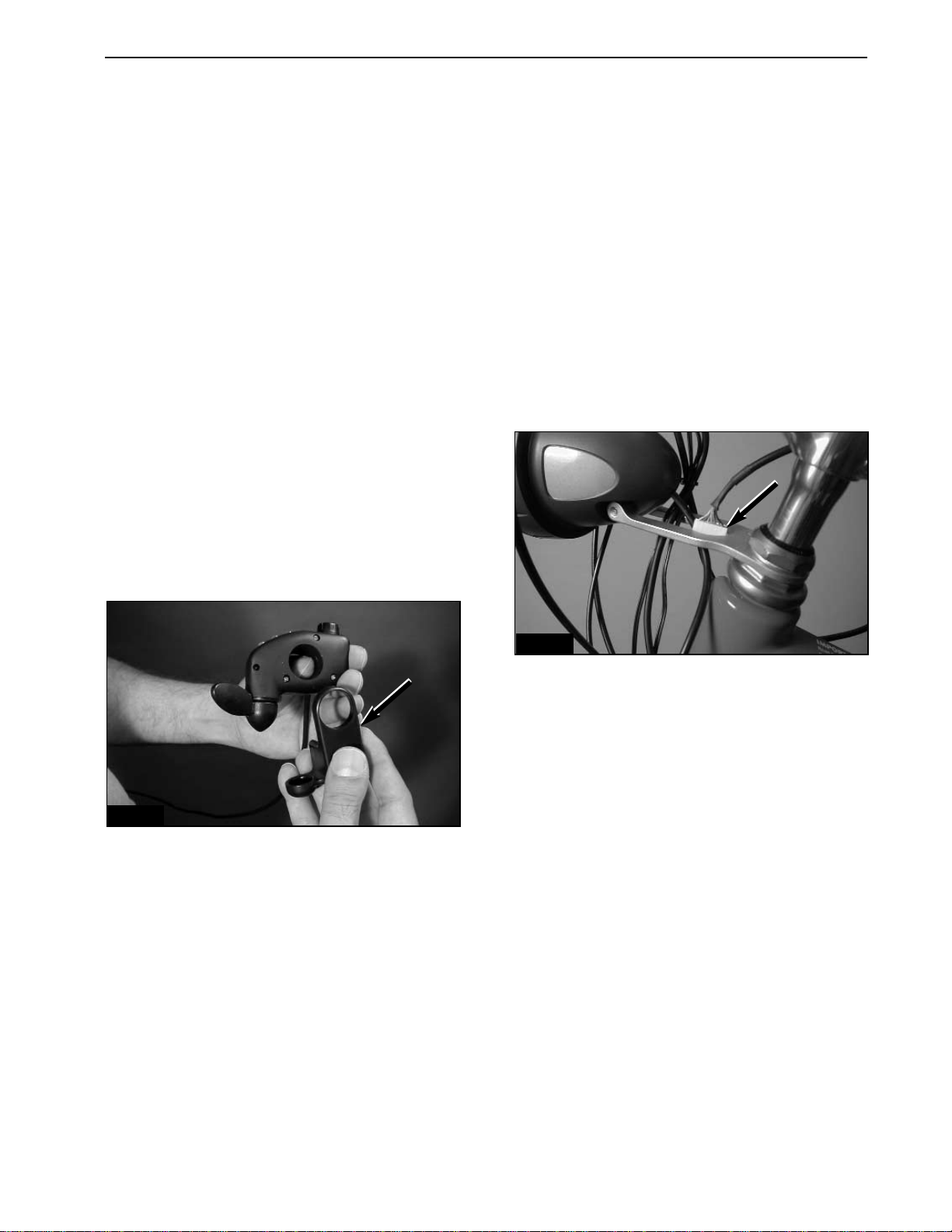
10. Loosen the set bolt on the throttle control.
11. Slide the throttle control and throttle stop
off the handlebar. Pull its wire free of the head-
light bracket.
Installation
1. Fit the throttle stop onto the bottom of the
throttle control (Figure 6).
2.Slide the throttle control and the throttle stop
onto the right handlebar.
3. Feed the connector end of the throttle con-
trol wire through the cutout in the headlight
bracket (Figure 7).
4. Feed the cable around the head tube,
through the cable inlet in the left side cover,
and plug the connector into position (F, Figure
4) on the controller panel.
5. Slide the right-brake-lever body onto the
right handlebar. Guide the front brake cable
around the headlight as you install the brake
lever body.
6. Finger tighten the clamp bolt to hold brake
body in place. Use the S-hook to secure the
front brake cable to the shifter cable (C, Figure 1).
7. Twist the right handlebar grip onto the han-
dlebar until the grip is flush with the end of the
handlebar.
8. Slide the brake lever body against the han-
dlebar grip. Position the brake lever as
described in Chapter Five, and torque the
clamp bolt to the specification in Table 4.
9. Slide the throttle control/throttle stop
assembly against the brake lever. Rotate the
throttle control so the LEDs point to the rider’s
eyes.Tighten the clamp bolt so there is enough
friction to hold it in place. Do not over tighten
the clamp bolt.
10. Reinstall the right side cover.
ACCESSORY CONTROL (LEFT SIDE)
Removal
1. Remove the battery from the battery com-
partment.
2. Remove the right side cover from the E-
Bike™.
3. Pull the cable inlet cover around the head
tube, and remove the cable inlet cover from the
left side cover.
4. Disconnect the accessory control connec-
tor (E, Figure 4) from the controller board.
Note how the accessory control wire is routed
through the frame.The new wire will have to be
rerouted along the same path.
5. Pull the wire so the connector passes
through the frame and emerges at cable inlet
in the left side cover (Figure 5).
FIG. 6
FIG. 7
HANDLEBAR and CONTROLS 4-3
This manual suits for next models
1
Table of contents


