EVA EVAstream FIT Manual

Wiring Diagrams V22.3 1
EVA Tech B.V.
De Velde 1
8064 PH Zwartsluis
The Netherlands
www.evastream.nl
DE
FR
ES
NL
EVA Wiring diagrams
EVAstream & DMX (P3 - P4)
EVAstream & Piezo (P5 –P9)
EVAstream & ECA-PRO (P10 –P13)
EVA RGBW lighting (P14 –P16)

Wiring Diagrams V22.3 2
Safety warnings
WARNING! Switch off all relevant live cables before starting installation.
RISK OF ELECTRIC SHOCK OR INJURY. The EVAstream and its control accessories must be installed by a certified electrician in accordance with
applicable local rules and regulations. Incorrect installation can cause electrical hazards.
CAUTION! Carefully read the separately enclosed document “Safety instructions mounting & installation EVAstream” before proceeding to mounting and/or
installation of the EVAstream and/or associated accessories and controls.
The EVAstream is a powerful machine. The machine includes a very powerful motor with rotating propeller. Carefully follow the supplied instructions for
mounting, electrical installation and use of the EVAstream. Failure or insufficient compliance with these important instructions can result in serious personal
injury or property damage. We do not accept any claim under warranty and/or liability for material and/or immaterial damage as a result of non-compliance with
these instructions regarding installation, assembly and use.

Wiring Diagrams V22.3 3
Motor Control Unit | DMX Ready
Article: EVA-SP-xxx-MCU-DMX
ADV)
With Piezo/DMX Advanced (EVO) Control start address = 5
Always cut off power before
servicing the engine
For connecting DMX control advanced (EVA-AA-77SL) or
EVA ECA Controller (SP/EVA-ECA-PRO)

Wiring Diagrams V22.3 4

Wiring Diagrams V22.3 5
Motor Control Unit | Piezo Ready
ADV)
Article: EVA-SP-xxx-MCU-PIEZO
Always cut off power before
servicing the engine

Wiring Diagrams V22.3 6

Wiring Diagrams V22.3 7
1
32
EVAstream Piezo PCB | Settings
Article: SP-PIEZO-ADV-PCB / SP-PIEZO-PSU-ADV
Stream controller V1
Rotary Switch Settings
CONFIG
1x
Piezo
2x
Piezo
3x Piezo
Basic
3x Piezo
Training
Rotary 3
8
1
1
1
Rotary 2
1
0
0
3
Rotary 1
5
6
9
9
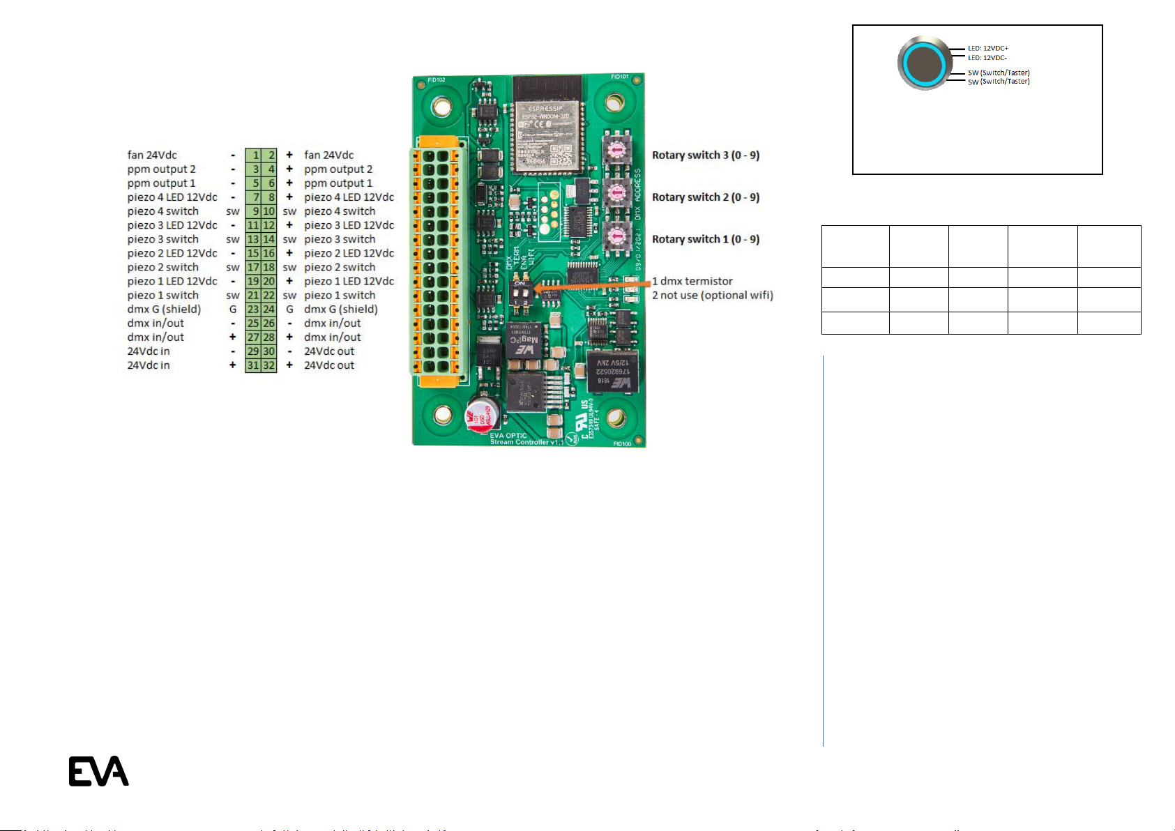
Slave mode: External master (DMX
Advanced Controller) control*
Rotary = dmx address 1-511
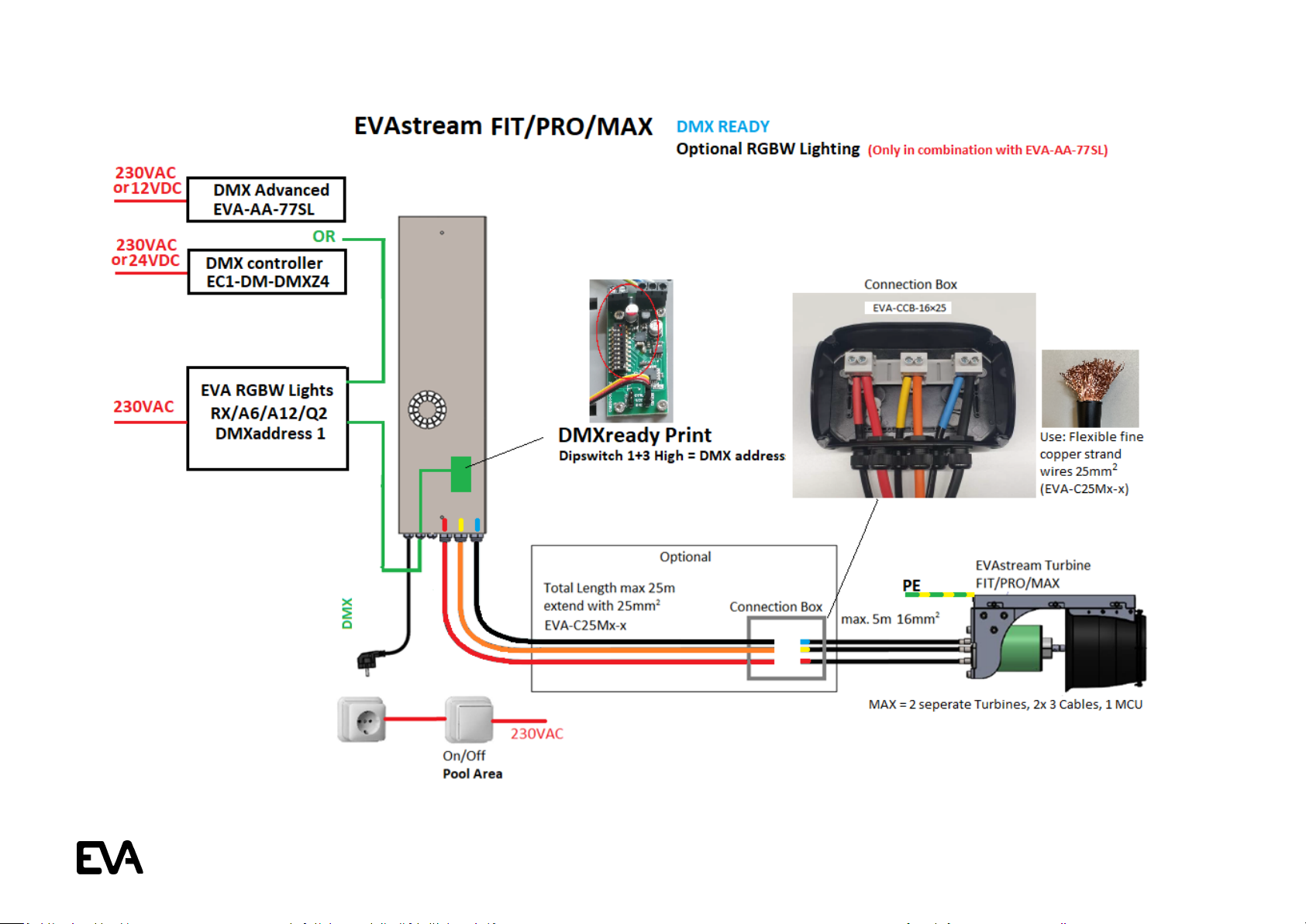
PPM output 1-2 to EVAstream motor control
Piezo 1 + 3 is pauze
Piezo 1 = speed +
Piezo 3 = speed -
Piezo 2 = on/off funtion
When no start/stop switch in pool, place a bridge
over sw/sw (piezo 2)
When using an EVA DMX controller as master,
use DMX start address 5
*Combining a DMX Advanced Controller with
Piezo is only possible with a Piezo Ready Motor
Control Unit (Art.no: EVA-SP-xxx-MCU-PIEZO)
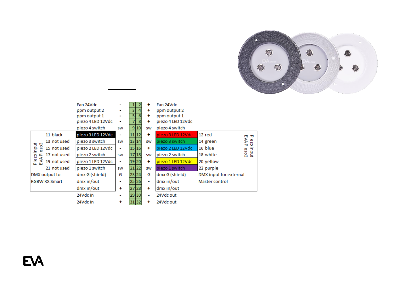
Master mode: piezo control
DMX in/out goes to EVAstream/UWL (underwater lighting) DMX input
Piezo/switch 4 = stop (reset) outside pool
Rotary (dmx) address 518 = 1 x piezo (1) control in 10% steps + (0, 30, 40, 50, 60, 70, 80, 90, 100)
When no start/stop switch in pool, place a bridge over sw/sw (piezo 2)
Rotary (dmx) address 601 = 2 x piezo (1+3) piezo 1 = speed +, piezo 3 = speed -, piezo 1+3 = on/standby. In standby piezo 3 = off
Rotary (dmx) address 901 = 3 x piezo (1+2+3) piezo 1 = speed +, piezo 2 = on/standby, piezo 3 = speed -. In standby piezo 3 = off
Rotary (dmx) address 931 = 3 x piezo (1+2+3). Step 1 = select user (piezo 1 or 2 or 3). Step 2 = select training
(piezo 1 or 2 or 3 --> make selection within 5 seconds otherwise step 2 is skipped, automatic proceeding to step 3)
* In training mode (step 2) piezo 1 = speed +, piezo 2 = standby, piezo 3 = speed -. In standy piezo 3 = off
* In stap 3 (stap 2 skipped) piezo 1 = speed +, piezo 2 = standby, piezo 3 = speed -. In standby piezo 3 = off
When using rotary (dmx) address 901/931, connect underwater lighting (UWL) to DMX in/out. Control UWL, see below:
UWL control: piezo 1+3 = switch colour, piezo 1+2 = light intensity -, piezo 2+3 = light intensity +
DMX start address (UWL and EVAstream) in master mode: UWL= dmx channel 1, EVAstream= dmx channel 5
Wire colour for each Piezo type different
Couleur de fil différente pour chaque type de piézo
Color de cable diferente para cada tipo piezoeléctrico
Aderfarbe per Piezo Typ unterschiedlich
Aderkleur per Piezo type verschillend

Wiring Diagrams V22.3 8
EVA Piezo3 | Wiring diagram for Piezo3 (7-wired cable)
to SP-PIEZO-ADV-PCB / SP-PIEZO-PSU-ADV (EVAstream Piezo PCB)
Article: SP-PIEZO3-W, SP-PIEZO3-G or SP-PIEZO3-A
Connect wires (7-wired cable) according to schematics below,
use wire colours as indicated:

Wiring Diagrams V22.3 9
EVA PiezoSQ3 / PiezoSQ4 | Wiring Diagram for PiezoSQ3/SQ4
to SP-PIEZO-ADV-PCB / SP-PIEZO-PSU-ADV (EVAstream Piezo PCB)
Article: EVA-PIEZOSQ4-AMB-X OR EVA-PIEZOSQ3-AMB-X
For cable extension, use data cable with minimum conductor size 0,25mm2 and with a
maximum cable length of 30 meters. Recommended cable type LiYY 16 x 0,25mm2 (Lapp
Unitronic) or equal. It is allowed to connect EVA-PIEZOSQ4-AMB-X and SP-PIEZO3-X
parallel to SP-PSU-ADV. It is also possible to combine wires 7,9,11,13,15,17,19,21 to:
Piezo 4 switch sw 9. In this case, it is important to use a cable with a conductor size of
0,5mm2.
Please note! Always check the Piezo wiring (conductor) colors
and the 12Vdc polarity before installation
L: 152 mm
H: 81 mm
4
2
3
1
L: 81 mm
H: 81 mm
2
3
1

Wiring Diagrams V22.3 10
Motor Control Unit | ECA Ready
PER 01-06-2022 STANDARD for EVAstream SET
Article: EVA-SP-xxx-MCU-ECA
EVA Experience Controller wiring schematic: see manual
Article code: SP/EVA-ECA-PRO
Always cut off power before
servicing the engine

Wiring Diagrams V22.3 11

Wiring Diagrams V22.3 12
EVA Experience Controller PCB | Settings
Article: SP-ECA-PRO / EVA-ECA-PRO
Stream controller V2
Controlling EVAstream + lighting by APP
Basis configuration is control by APP + piëzo unit
Rotary switches at 000 (factory settings, mastermode)
Slow down and speed up in 5% increments
See wiring schematic Piezo3 to SP/EVA-ECA-PRO
Controlling EVAstream by piëzo without APP
Rotary switches at 701
Slow down and speed up in 10% increments
See wiring schematic Piezo3 to SP/EVA-ECA-PRO
Controlling EVA Lighting by piëzo without APP
Rotary switches at 801
See wiring schematic Piëzo3 to SP/EVA-ECA-PRO
Rotary switch 3 (0-9)
Rotary switch 2 (0-9)
Rotary switch 1 (0-9)
Slave mode: External master Control (DMX advanced controller) *
Rotary switches at 005, DMX addresses EVAstream 5 and 6
When using a DMX advanced controller as master, use DMX start address 5.
Piëzo 2 = pass / pause DMX signal (note! the turbine pauses, but the scene continues in the DMX master)
Piëzo 1 = slow down
Piëzo 3 = speed up to maximum speed of the chosen scene (f.e. scene 70% : the maximum speed in this scene is 70%).
DMX master and no piëzo / start-stop switch in the pool? Place a bridge over SW/SW Piezo2.
1 dmx termistor
2 wifi: turn on for installation
Turn off immediately after installation
How the lamp groups are divided:
DMX 001 group 1 = underwater lighting (always responding to training)
DMX 011 Group 2
DMX 021 Group 3
DMX 031 Group 4

Wiring Diagrams V22.3 13
EVA Piezo3 | Wiring diagram for Piezo3 (7-wired cable)
to SP-ECA-PRO / EVA-ECA-PRO (Experience Controller PCB)
Article: SP-PIEZO3-A, SP-PIEZO3-G or SP-PIEZO3-W
2
>II
Piëzo control EVAstream incl. EVA lighting (by APP)
Rotary switches at 000
2 = start / pause
1 = slowdown (in 5% increments)
3 = speed up (in 5% increments)
1+3 = child lock (operation only possible by Web interface)
1
--
3
++
Piëzo control EVAstream excl. EVA lighting (without APP)
Rotary switches at 701
2 = on / stand-by (pause)
1 = slowdown in 10% increments / in stand-by start on 30%
3 = speed up in 10% increments / in stand-by start on 100%
Piëzo control EVA lighting (without APP)
Rotary switches at 801
2 = stand-by / on / scene-memory
1 = last scene / on
3 = next scene / on
Connect wires (7-wired cable) according to schematics below,
use wire colours as indicated:

Wiring Diagrams V22.3 14
EVA RGBW LED driver | Wiring Diagram LED driver 4+2 channel for EVA RGBW lighting
Article: SP-DR-DMX-4CH
Connect wires according to schematics below, use wire colors as indicated:
Master Mode:
First print (master) = Rotary address 605:
Piezo 1: light scene NEXT
Piezo 2: light scene PREVIOUS
Piezo 3: ON/OFF
Use Piëzo 1 SW 11/12 for controlling by pulse, remote control, ,
Piëzo or domotica.
Sequence scenes (with scene memory):
White/Sky Blue/Blue/Mediterranean/Green/Red/ Purple/Colour
Show Fade/Colour Show Jump
Next prints (slaves) = Rotary address 001 –511 (slave mode)
ATTENTION: The automatic start-up procedure takes approx.
30 seconds. During this procedure the lights will first light up
blue (softly). After that they will flash white. Start-up
procedure is ready now.
Alternative Master mode
600: no scene memory
615: sequence scenes (with scene memory): White/Sky
Blue/Blue/Mediterranean/Green/Red/ Purple/Colour
Show Fade/Colour Show Jump/OFF
Status leds
Orange: DMX is connected or PCB set as Master
Green flashing with high sequence: Starting software on PCB|
Green flashing with sequence of 1 sec: PCB is ready.
Red: An Issue has occurred. (please check the webapp (via WIFI) for
the event details)
External DMX512 control
All PCB’s DMX address 001 to 511
Depending on the DMX programming
Mostly address 001 at all PCB.
Examples, in combination with:
-EC2 DMX controller: 001
-EVA-AA-77 AND EVA-AA-77SL with standard program:
001
-EVAstream: 001
If there occur problems with the operation of the PCB, you can read
the PCB via WIFI. See manual WIFI Connection.
1
Wire colour for each Piezo type different
Couleur de fil différente pour chaque type de piézo
Color de cable diferente para cada tipo piezoeléctrico
Aderfarbe per Piezo Typ unterschiedlich
Aderkleur per Piezo type verschillend

Wiring Diagrams V22.3 15
EVA Piezo3 | Wiring Diagram Piezo3
to SP-DR-DMX-4CH (EVA RGBW LED driver)
Article: SP-PIEZO3-W, SP-PIEZO3-G or SP-PIEZO3-A
3
2
1
Set the 4-channel EVA LED Driver (SP-DR-DMX-4CH), to which the Piezo Controller is being connected, to Master mode (rotary address 600).
Connect the other lights via DMX in/out. Set these to Slave mode (rotary address 001).
Operation of the Piezo switches is then as follows:
Piezo 1: light scene NEXT
Piezo 2: light scene PREVIOUS
Piezo 3: ON/OFF
Sequence scenes: White/Sky Blue/Blue/Mediterranean Blue/Green/Red/Purple/Colour Show Fade/Colour Show Jump
Connect wires (7-wired cable) according to schematics below, use wire colors as indicated:

Wiring Diagrams V22.3 16
EVA Piezo3 | Wiring Diagram Piezo3
to SP-DR-DMX-4CH (EVA RGBW LED driver)
Article: EVA-PIEZOSQ3-AMB-X
Please note! Always check the Piezo wiring (conductor) colors and the 12Vdc
polarity before installation
L: 81 mm
H: 81 mm
2
3
1
Set the 4-channel EVA LED Driver (SP-DR-DMX-4CH), to which the Piezo Controller is being connected, to Master mode (rotary address 600).
Connect the other lights via DMX in/out. Set these to Slave mode (rotary address 001).
Operation of the Piezo switches is then as follows:
Piezo 1: light scene NEXT
Piezo 2: light scene PREVIOUS
Piezo 3: ON/OFF
Sequence scenes: White/Sky Blue/Blue/Mediterranean Blue/Green/Red/Purple/Colour Show Fade/Colour Show Jump
For cable extension, use data cable with minimum conductor size 7x0,5mm2 and with a maximum cable length of 30 meters. Recommended cable type LiYY
7x 0,5mm2 (Lapp Unitronic) or equal.
This manual suits for next models
13
Table of contents
Other EVA Lighting Equipment manuals
Popular Lighting Equipment manuals by other brands

PATIOJOY
PATIOJOY HW70304 Assembly instructions

Chauvet
Chauvet Colordash Block user manual

STKR
STKR FUL PRO LIGHT TELESCOPING 12679 quick start guide

ADB
ADB Signature Series manual

Beamz professional
Beamz professional BAC504 instruction manual

Clevertronics
Clevertronics L10 CleverFit Exit LCFLED Series ASSEMBLY, INSTALLATION & MAINTENANCE INSTRUCTIONS