EVAPCO AT Series Troubleshooting guide
Bulletin 113-E Metric
EVAPCO Products are Manufactured Worldwide
EVAPCO, Inc. (World Headquarters) P.O. Box 1300, Westminster, Maryland 21158 USA
Phone (410) 756-2600 - Fax (410) 756-6450
EVAPCO Europe bvba
Heersterveldweg 19
Industrieterrein Oost
3700 Tongeren, Belgium
Phone: (32) 12 395029
Fax: (32) 12 238527
E-mail: evapco.europe@ evapco.be
EVAPCO Europe S.r.l.
Via Ciro Menotti 10
I-20017 Passirana di Rho
Milan, Italy
Phone: (39) 02 9399041
Fax: (39) 02 93500840
Email: [email protected]
EVAPCO Europe GmbH
Insterburger Straße, 18
D-40670 Meerbusch, Germany
Phone: (49) 2159-6956-0
Fax: (49) 2159-6956-11
Email: [email protected]
EUROPEAN
OPERATION AND MAINTENANCE INSTRUCTIONS
For EVAPCO Induced Draft and Forced Draft Cooling Towers
For EVAPCO Authorized Parts and Service,
Contact Your Local Mr. GoodTower®Service Provider
or the EVAPCO Plant Nearest You
www.evapco.eu
AT UAT LSTE LPT PMTQ

2
Table of Contents
Introduction ....................................................................................................................................3
Safety Precautions / Remaining Risks ...............................................................................................3
Installation Precautions..............................................................................................................4
Storage Precautions ..................................................................................................................4
Label on the casing section(s) ...................................................................................................4
Checklists ....................................................................................................................................5
Initial and Seasonal Start-Up Checklist......................................................................................5
Maintenance Checklist...............................................................................................................6
Seasonal Shut-Down Checklist..................................................................................................7
Basic Cooling Tower Sequence of Operation ...................................................................................8
Fan System ....................................................................................................................................9
Fan Motor Bearings ...................................................................................................................9
Fan Shaft Ball Bearings .............................................................................................................9
Recommended Bearing Lubricants.............................................................................9
Fan Shaft Sleeve Bearings...................................................................................................................10
Fan Belt Adjustment .............................................................................................................................10
Fan and Motor Sheave Alignment............................................................................................ 11
Fan System Capacity Control ..................................................................................................12
Fan Motor Cycling.....................................................................................................12
Two Speed Motors ....................................................................................................12
Variable Frequency Drives........................................................................................12
Identify and Lock-out Harmful Resonant Frequencies...................................................................13
Recirculated Water System Routine Maintenance ..........................................................................13
Suction Strainer Assembly .......................................................................................................14
Cold Water Basin .....................................................................................................................14
Operating Water Levels ...........................................................................................................14
Water Make Up Valve ..............................................................................................................15
Drift Eliminators........................................................................................................................15
Pressurized Water Distribution System....................................................................................15
Bleed-Off Valve ........................................................................................................................16
Water Treatment and Water Chemistry ............................................................................................17
Bleed or Blowdown ..................................................................................................................17
Galvanized Steel - Passivation ................................................................................................17
Water Chemistry Parameters...................................................................................................18
Control of Biological Contamination.........................................................................................18
Gray Water and Reclaimed Water ...........................................................................................19
Air Contamination ....................................................................................................................19
Stainless Steel ..................................................................................................................................19
Maintaining the Appearance of Stainless Steel........................................................................20
Cleaning Procedures for Stainless Steel .................................................................................20
Cold Weather Operation ....................................................................................................................21
Troubleshooting .................................................................................................................................25
Replacement Parts .............................................................................................................................28
PartIdenticationDrawings
AT/UAT - 1,2 m Wide Units .......................................................................................29
AT/UAT - 2,4 and 2,6 m Wide Cells ..........................................................................30
AT/UAT - 3 and 3,6 m Wide Cells .............................................................................31
AT/UAT - 4,2 m Wide Cells .......................................................................................32
LPT - All Models........................................................................................................33
LSTE - 1,6 m Wide Units ..........................................................................................34
LSTE - 2,4 and 3 m Wide Units ................................................................................35
PMTQ .......................................................................................................................36
AT/UAT with Super Low Sound Fan - 2,4 and 2,6 m Wide Cells ..............................37
AT/UAT with Super Low Sound Fan - 3; 3,6 and 4,2 m Wide Cells ..........................38

3
Introduction
Congratulations on the purchase of your EVAPCO evaporative cooling unit. EVAPCO equipment is constructed of
the highest quality materials and designed to provide years of reliable service when properly maintained.
Evaporative cooling equipment is often remotely located and periodic maintenance checks are often overlooked. It is
important to establish a regular maintenance program and be sure that the program is followed. This bulletin should
be used as a guide to establish a program. A clean and properly serviced unit will provide a long service life and
operateatpeakefciency.
This bulletin includes recommended maintenance services for unit start up, unit operation and unit shutdown and the
frequency of each. Please note: the recommendations of frequency of service are minimums. Services should be
performed more often when operating conditions necessitate.
Become familiar with your evaporative cooling equipment. Refer to the isometric drawings located on pages 30-39 for
information on the arrangement of components in your equipment.
If you should require any additional information about the operation or maintenance of this equipment,
contact your local EVAPCO representative. You may also visit www.evapco.eu for more information.
Safety Precautions / Remaining Risks
Qualiedpersonnelshouldusepropercare,proceduresandtoolswhenoperating,maintainingorrepairingthisequipment
in order to prevent personal injury and/or property damage. The warnings listed below are to be used as guidelines only.
WARNING: Evaporative cooling equipment is considered as “Partly completed machinery”. “Partly completed machinery” is
a totality which almost forms a machinery but in itself cannot fulfil any particular function. The considered cooling
equipment is missing the components to safely connect it to the source of energy and motion in a controlled way.
The considered cooling equipment is custom made but is not designed to address the specific needs and safety
measures for a specific application. Each application requires a unique designed and integrated operational,
control and safety strategy that links all components of the installation and eventually a back-up system in a safe
and controlled way.
WARNING: This equipment should never be operated without fan screens and access doors properly secured, locked and
in place.
WARNING: For assembling or disassembling the unit or unit sections, please follow the rigging instructions or the
instructions on the yellow labels on the individual unit sections.
WARNING: During maintenance operations, the worker must use adequate personal protection equipment (PPE - A
minimum, but not limited list of PPE are safety shoes, glasses, gloves, respiration protection, helmet) as
prescribed by local authorities.
WARNING: For any exceptional, non routine work to be carried out, protection and adequate safety measures should be
considered and a Last Minute Risks Assessment (LMRA) must be made by an authorized person in accordance
with safety requirements of the country.
WARNING: A lock-out / tag-out procedure, integrated with the Process Control System, must be foreseen by the
customer. Before performing any type of service or inspection of the unit, make certain that all power has
been disconnected and locked in the “OFF” position.
WARNING: The top horizontal surface of any unit is not intended to be used as a working platform. No routine service
work is required from this area. For any exceptional, non routine work to be carried out on top of the
unit, use ladders, PPE and adequate safety measures against the risk of a fall, in accordance with safety
requirements of the country in question.
WARNING: The recirculating water system may contain chemicals or biological contaminants including Legionella
Pneumophila, which could be harmful if inhaled or ingested. Direct exposure to the discharge airstream
and the associated drift generated during operation of the water distribution system and/or fans,
or mists generated while cleaning components of the water system, require respiratory protection
equipment approved for such use by governmental occupational safety and health authorities.
WARNING: To avoid water and air contamination as a result of biological fouling, the cooling equipment must be
maintained in accordance, but not limited to the operating and maintenance instructions. All local
legislation related to evaporative cooling equipment must be respected.
WARNING: Accessories like platform and ladders are optional. In case these options are not taken in consideration, the
customer must design the installation to comply with local safety and access requirements and legislation.
WARNING: Sound reducing options are available. In case these options are not taken in consideration, the customer
must design the installation to comply with local sound requirements and legislation.
4
Installation Precautions
WARNING: The water inlet and outlet connections are not designed to support piping. The piping always need to be
supported (by others).
Storage Precautions
WARNING: Never use plastic sheets or tarps to protect a unit during storage. This practice can trap heat inside the
unit and could potentially cause damage to plastic components.
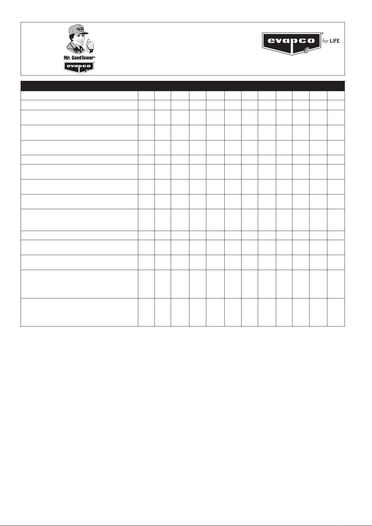
Label on the casing section(s)
.
2A(2)
2(2)
35
17A
33
2 EVAPCO LOGO (both sides)
2A RIGGING INSTRUCTIONS (both ends)
33 WATER IN
17A WARNING ELIMINATORS
35 DO NOT COVER ELIMINATORS

5
Initial and Seasonal Start-Up Checklist
General
1. VerifythattheoverallinstallationreectstherequirementsoftheinstallationguidelinesfoundinEVAPCO
Bulletin 311 - Equipment Layout Manual, available at www.evapco.eu.
2. For multi-speed fan motors, verify that 30 second or greater time delays are provided for speed changes
when switching from high to low speed. Also check to see if interlocks are provided to prevent simultaneously
energizinghighandlowspeedandconrmbothspeedsturninthesamedirection.
3. Verify all safety interlocks work properly.
4. For units operating with a variable frequency drive, make certain that minimum speed requirements have
been set. Check with VFD manufacturer for recommended minimum speeds and recommendations on
locking out resonance frequencies.
5. Verify that the sensor used for fan sequencing and/or by-pass valve control is located downstream of the
point where the by-pass water mixes with the condenser supply water, if applicable.
6. Verify that a water treatment plan has been implemented including passivation of galvanized steel units. See
“Water Treatment” section for more details.
7. For units subject to freezing climates, high humidity climates, or idle periods lasting 24 hours or more,
motor space heaters are suggested and (if equipped) should be energized. Alternatively, fan motors may be
energized for 10 minutes, twice daily, to drive any moisture condensation out of the motor windings.
8. If the unit is going to sit idle for an extended period of time, follow all manufacturers’ fan motor and pump
instructions for long term storage. Plastic sheets or tarps should never be used to protect a unit during storage.
This practice can trap heat inside the unit, and could potentially cause damage to plastic components. See your
local EVAPCO representative for additional information on unit storage.
BEFORE BEGINNING ANY MAINTENANCE, BE CERTAIN THAT THE POWER IS
TURNED OFF AND THE UNIT IS PROPERLY LOCKED AND TAGGED OUT!
Initial and Seasonal Start-Up
1. Clean and remove any debris, such as leaves and dirt from the air inlets.
2. Flush the cold water basin (with the strainer screens in place) to remove any sediment or dirt.
3. Remove the strainer screen, clean and reinstall.
4. Checkmechanicaloatvalvetoseeifitoperatesfreely.
5. Inspect water distribution system nozzles and clean as required. Check for proper orientation. (This is not
required at initial start-up. The nozzles are clean and set at the factory).
6. Check to ensure drift eliminators are securely in place and in proper orientation.
7. Adjust fan belt tension as required. See “Fan Belt Adjustment” section.
8. Lubricate fan shaft bearings prior to seasonal start-up.
9. Turn the fan(s) by hand to insure it turns freely without obstructions.
10. Visually inspect the fan blades. Blade clearance should be approximately 10 mm (min. 6 mm) from tip of
blade to the fan cowl. The fan blades should be securely tightened to the fan hub.
11. If any stagnant water remains in the system including “dead legs” in the piping, the unit must be disinfected
prior to the fans being energized. Please refer to ASHRAE Guideline 12-2000 and CTI Guideline WTP-148
for more information and consult local legislation prior to start-up.
12.Fillthecoldwaterbasinmanuallyuptotheoverowconnection.
13. Allnewevaporativecoolingequipmentandassociatedpipingshouldbepre-cleanedandushedtoremove
grease, oil, dirt, debris and other suspended solids prior to operation. Any pre-cleaning chemistry should be
compatible with the cooling equipment’s materials of construction. Alkaline formulations should be avoided
for systems which include galvanized materials of construction [EU].
After the unit has been energized, check the following:
1. Adjustmechanicaloatvalveasrequired.
2. Unitbasinshouldbelledtotheproperoperatinglevel.See“RecirculatingWaterSystem–Operating
Levels” section for more details.
3. Verify fan is rotating in proper direction.
4. Measure voltage and current on all three power leads. The current must not exceed the
motor nameplate full load amp rating.
5. Adjustbleedvalvetoproperowrate.Maximumbleed-offis3,2l/minper100kW.
Consultyourqualiedwatertreatmentpersontonetunetheminimunbleednecessary.
6
MAINTENANCE
CHECKLIST
PROCEDURE
JAN FEB MAR APR MAY JUN JUL AUG SEP OCT NOV DEC
1. Clean pan strainer – monthly or as needed
2. Clean and ush pan** – quarterly or as needed
3. Check bleed-off valve to make sure it is operative
– monthly
4. Check operating level in pan and adjust oat
valve if necessary – monthly
5. Check water distribution system and spray
pattern – monthly
6. Check drift eliminators – quarterly
7. Check the fan blades for cracks, missing
balancing weights, and vibrations - quarterly
8. Check sheaves and bushings for corrosion.
Scrape and coat with ZRC - annually
9. Lubricate fan shaft bearings* - every 1000 hours
of operation or every three months
10. Lubricate fan motor bearings – see mfg’s
instructions. Typically for non-sealed bearings,
every 2-3 years
11. Check belt tension and adjust – monthly
12. Sliding motor base – Inspect and grease –
annually or as needed
13. Check fan screens, inlet louvers and fans.
Remove any dirt or debris - monthly
14. Inspect and clean protective nish – annually
- Galvanized: scrape and coat with ZRC
- Stainless: clean and polish with a stainless
steel cleaner.
15. Check water quality for biological contamination.
Clean unit as needed and contact a water
treatment company for recommended water
treatment program** – regularly
* See maintenance manual for start-up instructions and lubrication recommendations
** Cooling Towers must be cleaned on a regular basis to prevent the growth of bacteria including Legionella Pneumophila

7
MAINTENANCE
CHECKLIST
(optional accessories)
PROCEDURE
JAN FEB MAR APR MAY JUN JUL AUG SEP OCT NOV DEC
1. Coupling/Shaft – Inspect ex elements and
hardware for tightness, proper torque & crack/
deterioration – monthly
2. Heater Controller – Inspect controller and clean
probe ends – quarterly
3. Heater – Inspect junction box for loose wiring
and moisture – one month after start-up and
semi-annually
4. Heater – Inspect elements for scale build-up –
quarterly
5. Electronic Water Level Controller – Inspect
junction box for loose wiring and moisture –
semi-annually
6. Electronic Water Level Controller – Clean probe
ends of scale build-up – quarterly
7. Electronic Water Level Controller – Clean inside
the standpipe – annually
8. Solenoid Make-up Valve – Inspect and clean
valve of debris – as needed
9. Vibration Switch (mechanical) – Inspect
enclosure for loose wiring and moisture – one
month after start-up and monthly
10. Vibration Switch – Adjust the sensitivity – during
start-up and annually
11. Sump Sweeper Piping – Inspect and clean
piping of debris – semi-annually
DURING IDLE PERIODS:
1. Two or More Days: Energize motor space
heaters – or run motors for 10 minutes twice daily
2. One Month or longer: Rotate motor shaft/fan
10 turns – bi-weekly
3. One Month or longer: Megger test motor
windings – semi-annually
Seasonal Shut-Down Checklist
When the system is to be shut down for an extended period of time, the following services should be performed.
1. The evaporative cooling unit cold water basin should be drained.
2. Thecoldwaterbasinshouldbeushedandcleanedwiththesuctionstrainerscreensinplace.
3. The suction strainer screens should be cleaned and re-installed.
4. The cold water basin drain should be left open.
5. The fan shaft bearings and motor base adjusting screws should be lubricated. This should also be
performed if the unit is going to sit idle prior to start up.
6. The water make up valve needs to be closed. All water make-up piping needs to be drained, if not heat
traced and insulated.
7. Thenishoftheunitshouldbeinspected.Cleanandrenishasrequired.
8. The fan bearings and motor bearings need to be turned at least once a month by hand. This can be
accomplished by making sure the unit’s disconnect is locked and tagged out, and grasping the fan
assembly, rotating it several turns.
9. Energize motor space heaters.

8
Basic Cooling Tower Sequence of Operation
System Off / No Load
The system pumps and fans are off. If the basin is full of water a minimum basin water temperature of 4ºC must
be maintained to prevent freezing. This can be accomplished with the use of optional basin heaters. See the
“Cold Weather Operation” section of this bulletin for more details on cold weather operation and maintenance.
System / Condensing Temperature Rises
The system pump turns on. The unit will provide approximately 10% cooling capacity with only the pump running.
NOTE:Iftheloadissuchthatsimplyrunningthesystempumpwiththeunitfanmotoridleissufcient,
motor space heaters (if equipped) should be energized while the motor is idle. Alternatively, the motor can
be energized twiced daily for a minimum of 10 minutes to protect the motor insulation from damage.
If the system temperature continues to rise, the unit fan is cycled on. For a variable speed controller, the
fansareturnedontominimumspeed.Seethe“FanSystem–CapacityControl”sectionofthisbulletinfor
more details on fan speed control options. If the system temperature continues to rise, then the fan speed
is increased as required, up to full speed.
NOTE: During sub-freezing weather the minimum recommended speed for variable speed controllers
is 50%. ALL FANS IN OPERATING CELLS OF MULTIPLE CELL UNITS MUST BE CONTROLLED
TOGETHER TO PREVENT ICING ON THE FANS.
System Temperature Stabilizes
Control the leaving water temperature by modulating the fan speeds with variable speed drives or by
cycling fans on and off with single or two-speed drives.
System Temperature Drops
Decrease the fan speed, as required.
System Off / No Load
The system pump turns off. The starter interlock will energize any optional basin heaters in cold weather.
The recirculation pump should not be used as a means of capacity control, and should not be cycled
frequently. Excessive cycling can lead to scale build-up, and reduce wet and dry performance.
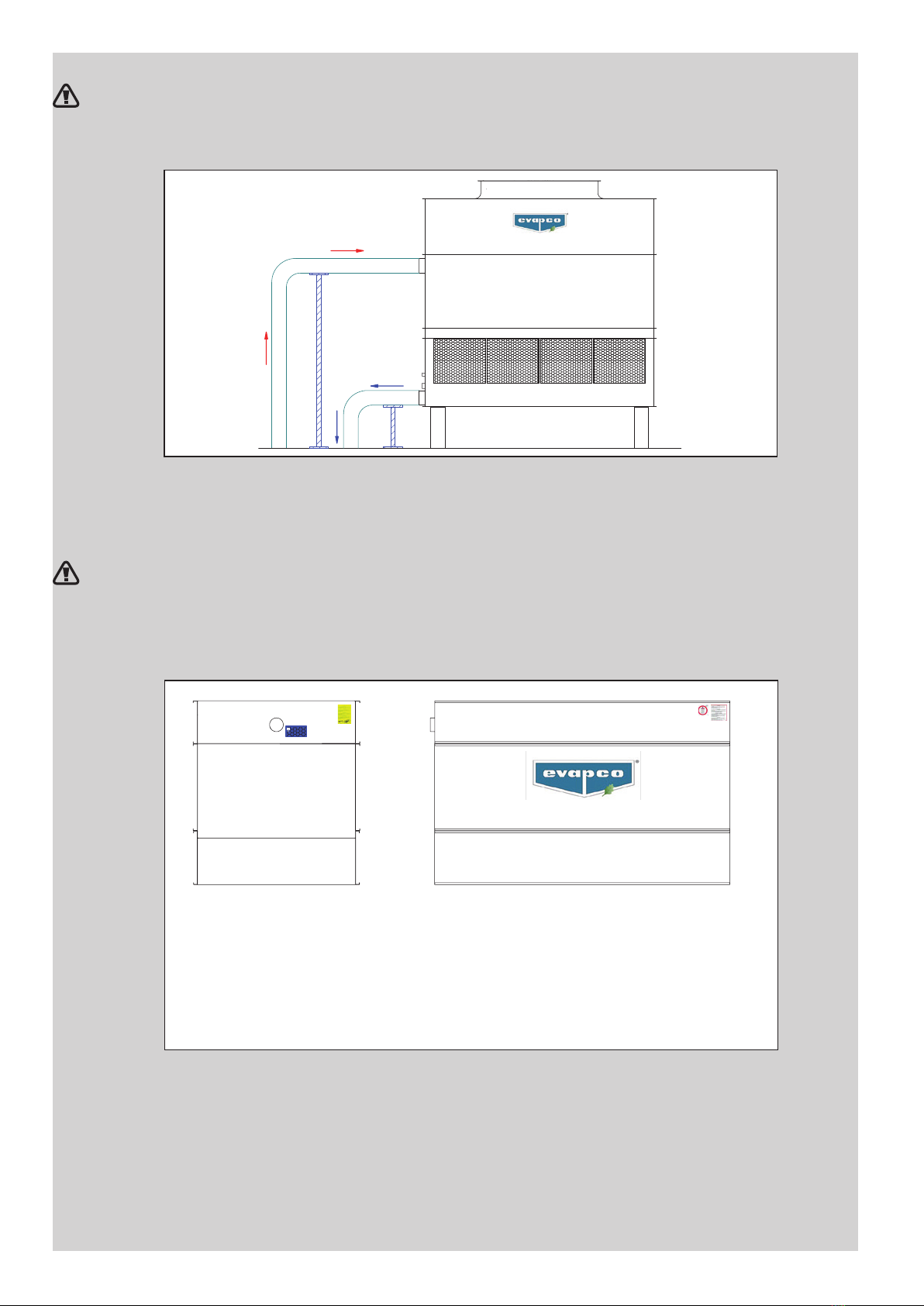
Bypass Mode
During winter months when cooling load is minimal, bypass mode may be used as a form of capacity
control. Bypass mode allows the water to “bypass” the tower’s water distribution system and deposits the
inlet water directly into the cold water basin. Alternatively, the incoming water bypass can be piped directly
to the return condenser header pipe. Please note: The location of the bypass valve should be 4,5 m
below the cooling tower cold water basin elevation to assure proper operation and prevent cavitation. This
bypass mode should be continued until the total water inventory reaches an acceptable temperature level
(usuallyabout27°C),atwhichtimethebypassmaybeclosedtocausetotalowoverthell.
EVAPCO does NOT recommend a partial water bypass due to the potential for freezing the heat transfer
media during low ambient operation.
Optional Defrost Cycle
In more severe climates, the incorporation of a defrost cycle may be used to manage the ice formation in
and on the unit. During the defrost cycle, the cooling tower fan(s) are reversed at no more than half speed
whilethesystempumpowswaterthroughthecoolingtower’swaterdistributionsystem.Operatingthe
unit in “reverse” will melt any ice that has formed in the unit or on the intake louvers. All multi-speed or
VFD duty motors supplied by EVAPCO for induced draft units, are capable of reverse operation.
Defrost cycles are NOT recommended for forced draft cooling towers. In these units, allowing the leaving
water temperature set point to rise causes the fans to be off for very long periods of time, which increases
the fan drive component potential for freezing. In lieu of a defrost cycle, forced draft units should be
operated at low speed (with a 2-speed motor) or minimum speed (no lower than 25% with a variable
frequency drives) in order to maintain positive pressure inside the unit to help prevent ice formation on the
fan drive components.
NOTE: MINIMUM CONTROL POINT FOR WATER SHOULD NEVER BE LOWER THAN 5°C.

9
Fan System
The fan systems of both centrifugal and axial driven units are rugged, however, the fan system must
be checked regularly and lubricated at the proper intervals. The following maintenance schedule is
recommended.
Fan Motor Bearings
EVAPCO evaporative cooling units use either a T.E.A.O. (Totally Enclosed Air Over) or a T.E.F.C. (Totally
EnclosedFanCooled)fanmotor.Thesemotorsarebuiltto“CoolingTowerDuty”specications.Thefan
motor bearings for motors up to 30 kW are lubricated for the lifecycle of the bearings, higher motor powers
require relubrication (please see motor manual for more detail). All fan motors are supplied with special
moisture protection on the bearings, shaft and windings. After extended shut-downs, the motor should be
checked with an insulation tester prior to restarting the motor.
Fan Shaft Ball Bearings
Lubricate the fan shaft bearings every 1,000 hours of operation or every three months for induced draft units.
Lubricate the fan shaft bearings every 2,000 hours of operation or every six months for forced draft units. Use
any of the following synthetic waterproof, inhibited greases which are suitable for operation between -40°C
and 120°C. (For colder operating temperatures, contact the factory).
Chevron - Multifak Premium 3 Total - Ceran WR2 or similar
Shell Alvanias
Feed grease slowly into the bearings or the seals may be damaged. A hand grease gun is
recommended for this process. When introducing a new grease, all grease should be purged from
the bearings.
Most EVAPCO units are supplied with extended grease lines to allow easy lubrication of the fan shaft
bearings.
Unit Description Location of Lube Line Fittings
InducedDraftUnits–2,4mwide Located just beside the fan casing
access door
InducedDraftUnits–2,6mwide Located just beside the fan casing
access door
InducedDraftUnits–3mwideand6mwide Located inside the fan casing
access door
InducedDraftUnits–3,6mwideand7,2mwide Located inside the fan casing
access door
InducedDraftUnits–4,2mwideand8,4mwide Located inside the fan casing
access door
LSTE Forced Draft Units Located on the front of the unit
LPT Forced Draft Units Located on the front of the unit
PMTQ Forced Draft Units Located on the front of the unit
Table 1 – Location of Grease Lube Line Fittings for Belt Driven Units
Please note, the removal of the fan screens is not necessary on forced draft units
to access the extended lube line ttings.
10
Fan Shaft Sleeve Bearings – (1,2 m wide LSTE units only)
Lubricate the intermediate sleeve bearing(s) before unit start up. The reservoir should be checked
severaltimesduringtherstweektoensurethattheoilreserveisbroughttofullcapacity.After
therstweekofoperation,lubricatethebearing(s)every1.000hoursofoperationorevery
threemonths(whicheveroccursrst).Hightemperaturesorpoorenvironmentalconditionsmay
necessitate more frequent lubrication. The oil reservoir consists of a large felt packed cavity within
thebearinghousing.Itisnotnecessarytomaintaintheoillevelwithinthellercup.
Use one of the following industrial grade, non-detergent mineral oils. Do not use a detergent
based oil or those designated heavy duty or compounded. Different oils may be required
when operating at temperatures below -1°C continuously. Table 2 provides a short list of approved
lubricants for each temperature range. Most automotive oils are detergent based and may not be
used. Detergent oils will remove the graphite in the bearing sleeve and cause bearing failure.
Ambient Temp. Texaco Mobil Exxon Total
-32°C to 0°C - DTE Heavy - -
-17°C to 43°C - - - -
0 to 38°C Regal R&O 220 DTE Oil BB Teresstic 220 -
Table 2 - Sleeve Bearing Lubricants
Oil drippage may result from over-oiling or from using too light an oil. Should this condition persist
with correct oiling, it is recommended that the next heavier weight oil be used.
All bearings used on EVAPCO equipment are factory adjusted and self aligning. Do not disturb
bearing alignment by tightening the sleeve bearing caps.
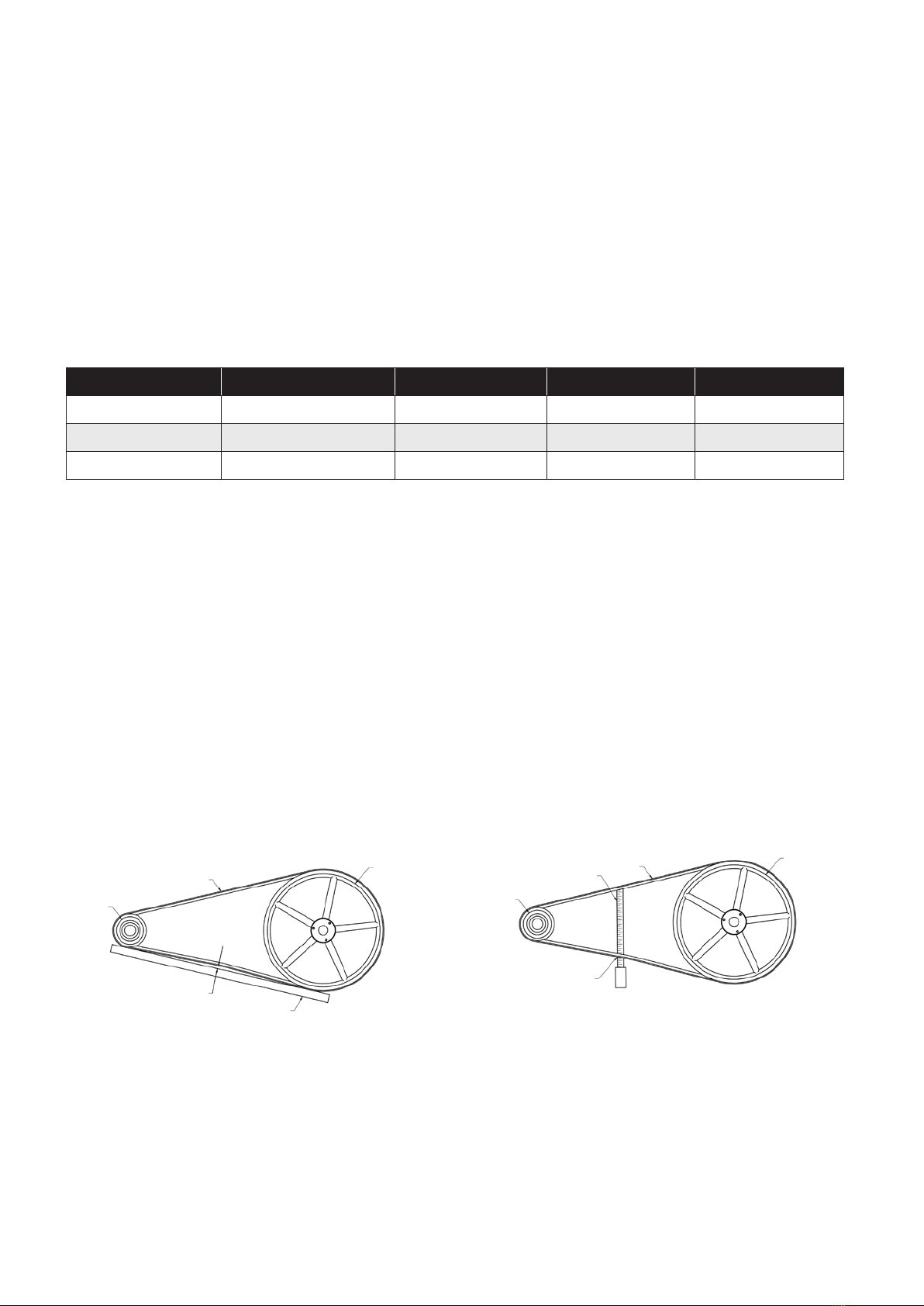
Fan Belt Adjustment
Thefanbelttensionshouldbecheckedatstartupandagainaftertherst24hoursofoperation
to correct for any initial stretch. To properly adjust the belt tension, position the fan motor so that
thefanbeltwilldeectapproximately13mmwhenmoderatepressureisappliedmidwaybetween
the sheaves.
Figure1andFigure2showtwowaystomeasurethisdeection.Belttensionshouldbecheckedon
a monthly basis. A properly tensioned belt will not “chirp” or “squeal” when the fan motor is started.
Figure 1 – Method 1 Figure 2 – Method 2
BELT
DRIVER
SHEAVE
DRIVEN
SHEAVE
STRAIGHT EDGE
13 mm DEFLECTION =
PROPER BELT TENSION
BELT
DRIVER
SHEAVE
DRIVEN
SHEAVE
TAPE MEASURE
13 mm DEFLECTION =
PROPER BELT TENSION
11
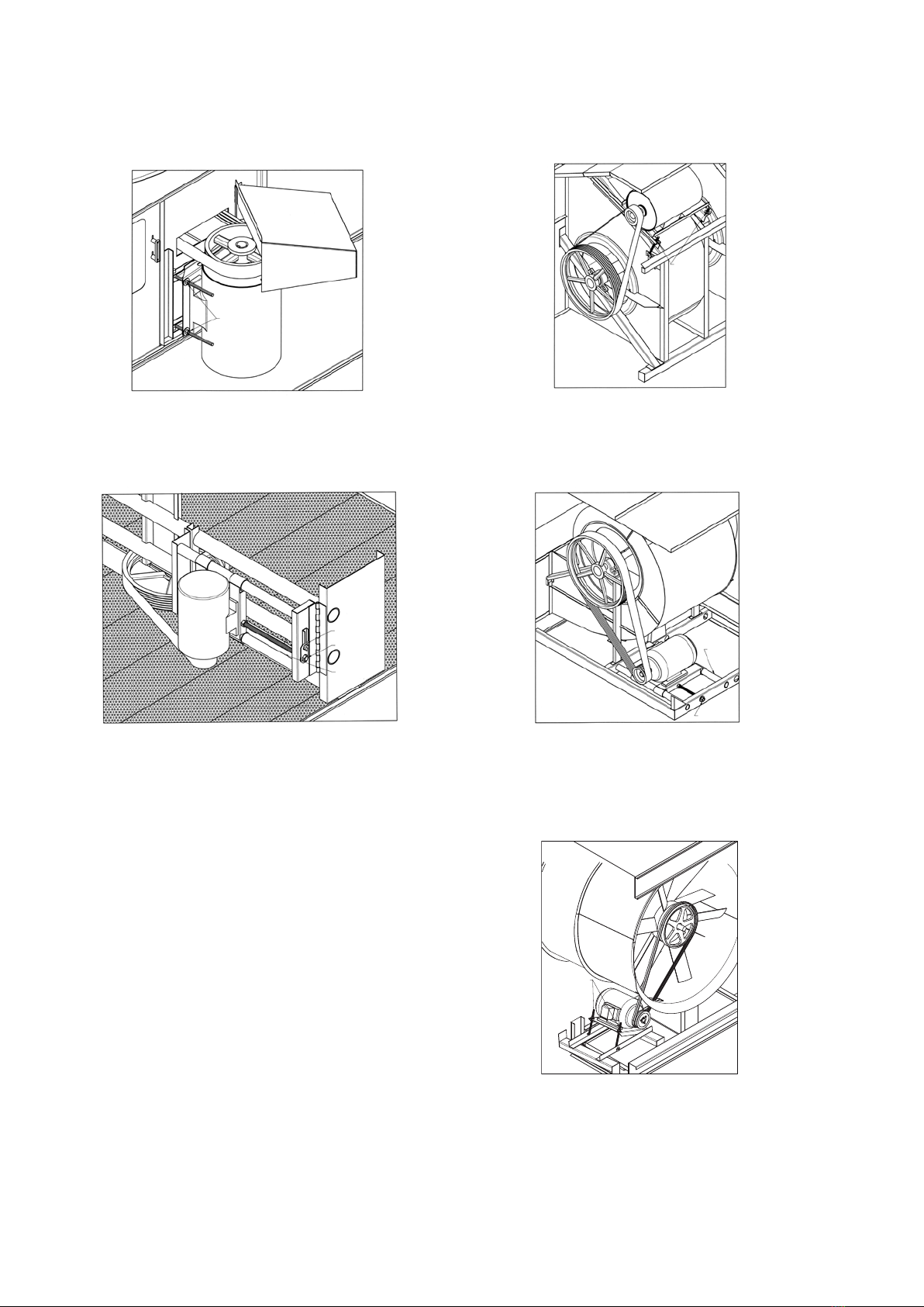
On induced draft belt driven units provided with externally mounted motors (2,4 and 2,6 m wide
units), Figure 3, LSTE forced draft units, Figure 4, and PM forced draft units, Figure 7, both J-type
adjustment bolts on the adjustable motor base should have an equal amount of exposed thread
for proper sheave and belt alignment.
Figure 3 – Externally Mounted Motors Figure 4 – LSTE Externally Mounted Motor
Figure 5 – Internally Mounted Motors Figure 6 – LPT Motor Adjustment
On induced draft belt driven units with internally
mounted motors (3 m; 3,6 m; 4,2 m; 6 m; 7,2 m
and 8,4 m wide units) as shown in Figure 5,
LPT units as shown in Figure 6 and PM units
as shown in Figure 7, a motor adjustment
tool is provided. The tool will be found on the
adjustment nut. To use, place the hex end over
the adjustment nut. Tension the belt by turning
the nut counterclockwise. When the belts are
properly tensioned, tighten the lock nut.
ADJUSTMENT
NUTS
ADJUSTMENT
NUTS
ADJUSTMENT NUT
ADJUSTMENT TOOL
SWING OUT
MOTOR BASE
SLIDING
MOTOR BASE
ADJUSTMENT NUT
ADJUSTMENT
NUT
Figure 7 – PM Style Motor Adjustment

12
Fan System — Capacity Control
There are several methods for capacity control of the evaporative cooling unit. Methods include: Fan motor cycling,
the use of two speed motors and the use of variable frequency drives (VFD’s).
In all cases, if motors are idle for extended periods of time with water still being directed over the heat transfer media,
motor space heaters are suggested.
Fan Motor Cycling
Fan Motor Cycling requires the use of a single stage thermostat which senses the water temperature. The contacts of
the thermostat are wired in series with the fan motor’s starter holding coil.
FanMotorCyclingisoftenfoundtobeinadequatewheretheloadhasawideuctuation.Inthismethod,thereare
only two stable levels of performance: 100% of capacity when the fan is on and approximately 10% of capacity when
the fan is off. Please note, rapid cycling of the fan motors can cause the fan motor to overheat. Controls should be
set to only allow a maximum of six (6) start/stop cycles per hour.
IMPORTANT
THE RECIRCULATION PUMP SHOULD NOT BE USED AS A MEANS OF CAPACITY CONTROL AND SHOULD
NOT BE CYCLED FREQUENTLY. EXCESSIVE CYCLING CAN LEAD TO SCALE BUILD-UP AND REDUCES THE
PERFORMANCE. FREQUENT CYCLING OF THE SPRAY PUMP, WITHOUT THE FANS IN OPERATION, WILL
PROVOKE DRIFT AND SPRAY WATER MIGRATION OVER THE AIR INLET LOUVERS, WHICH IS PROHIBITED
IN MOST COUNTRIES. PLEASE CONSULT YOUR LOCAL LEGISLATION.
Two Speed Motors
The use of a two speed motor provides an additional step of capacity control when used with the fan cycling method.
The low speed of the motor will provide 60% of full speed capacity.
Two speed capacity control systems require not only a two speed motor, but a two stage thermostat and the
proper two speed motor starter. The most common two speed motor is a single winding type. This is also known
as a consequent pole design. Two speed two winding motors are also available. All multi-speed motors used in
evaporative cooling units should be variable torque design.
It is important to note that when two speed motors are to be used, the motor starter controls must be equipped with
a decelerating time delay relay. The time delay should be a minimum of a 30 second delay when switching from high
speed to low speed.
Sequence of Operation for Two Fan Units with Two Speed Motors During Peak Load
1. Bothfanmotorsonfullspeed–fullwaterowoverbothcells
2. Onefanmotoronhighspeed,onefanmotoronlowspeed–fullwaterowoverbothcells
3. Bothfanmotorsonlowspeed–fullowoverbothcells
4. Onefanmotoronlowspeed,onefanmotoroff–fullwaterowoverbothcells
5. Bothfanmotorsoff–fullwaterowoverbothcells
6. Bothfanmotorsoff–fullsinglecellowthroughonecell
Variable Frequency Drives
The use of a variable frequency drive (VFD) provides the most precise method of capacity control. A VFD is a device
thatconvertsaxedACvoltageandfrequencyandchangesitintoanACadjustablevoltageandfrequencyused
to control the speed of an AC motor. By adjusting the voltage and frequency, the AC induction motor can operate at
many different speeds.
TheuseofVFDtechnologycanalsobenetthelifeofthemechanicalcomponentswithfewerandsmoothermotor
startsandbuiltinmotordiagnostics.VFDtechnologyhasparticularbenetonevaporativecoolingunitsoperating
incoldclimateswhereairowcanbemodulatedtominimizeicingandreversedatlowspeedforde-icingcycles.
Applications using a VFD for capacity control must also use an inverter duty motor built in compliance with IEC. This is
an available option from EVAPCO. The standard fan motors supplied by EVAPCO are not intended for use with VFD’s.
The type of motor, manufacturer of the VFD, motor lead lengths (between the motor and the VFD), conduit runs and
grounding can dramatically affect the response and life of the motor. The motor lead length restrictions vary with the
motor vendor. Regardless of motor supplier, minimizing motor lead length between the motor and the drive is good
practice.
Sequence of Operation for Multi-fan Units with a VFD During Peak Load
1. The VFDs should all be synchronized to speed up and slow down uniformly.
2. The VFDs need to have a pre-set shutoff to prevent water temperatures from becoming too cold and to
prevent the drive from trying to turn the fan at near zero speed.
3. Operating below 25% of motor speed achieves very little return in fan energy savings and capacity
control. Check with your VFD supplier if operating below 25% is possible.

13
Identify and Lock-out Harmful Resonant Frequencies
AVariableFrequencyDrive(VFD)fansystem,unliketraditionalxed-speedsystems,isdesignedtooperatebetween25%
(13Hz) and 100% (50Hz) speeds, which creates an opportunity for operation where resonant frequencies exist. Sustained
operation at resonant frequencies may lead to excessive vibration, fatigue of structural components and/or drive system noise
and failure. Owners and operators must anticipate the existence of resonant frequencies and lock out frequencies during
start-up and commissioning in order to prevent drive system operational problems and structural damage. As a part of the
normalstart-upandcommissionprocesses,resonantfrequenciesshouldbeidentiedandlocked-outintheVFD’ssoftware.
The unit’s supporting structure, external piping, and accessories contribute to the overall harmonic make-up and stiffness
ofthesystem.ThechoiceofVFDwillalsohaveasignicantinuenceonhowthesystembehaves.Consequently,not
allresonantfrequenciescanbedeterminedinadvanceatthemanufacturer’sfactoryduringnalinspectionandtesting.
Relevantresonantfrequencies(iftheyoccur)canonlybeidentiedaccuratelyaftertheinstallationinthesystem.
Tocheckforresonantfrequenciesintheeld,arun-upandrun-downtestmustbeperformed.Additionally,VFDcarrier
frequencies should be adjusted to best align the VFD with the electrical system. Refer to your drive’s start-up procedures
for additional information and instruction.
The procedure of checking for resonant frequencies requires stepping through the VFD’s operating range at (2) Hz
intervals from the lowest operating frequency to full speed. At each step, pause long enough for the fan to reach steady-
state. Note changes in unit vibration during this time. Repeat from full speed to minimum speed. Should vibration-inducing
frequencies exist, the run-up and run-down test will isolate the resonant frequencies which then must then be locked-out in
the VFD programming.
Recirculated Water System – Routine Maintenance
Suction Strainer in Cold Water Basin
Thepanstrainershouldberemovedandcleanedmonthlyorasoftenasnecessary.Thesuctionstraineristherst
line of defense in keeping debris out of the system. Make certain that the strainer is properly located over the pump
suction, alongside the anti-vortexing hood.
STRAINER
ASSEMBLY
STRAINER
HANDLE
ANTI-VORTEXING
HOOD
ANTI-VORTEXING
HOOD
STRAINER
ASSEMBLY
STRAINER
HANDLE
Figure 8 – Single Strainer Assembly Figure 9 – Dual Strainer Assembly
Figure 10 – LSTE / PMTQ Strainer Assembly Figure 11 – LPT Strainer Assembly
STRAINER
ASSEMBLY
STRAINER
HANDLE
ANTI-VORTEXING
HOOD
ANTI-VORTEXING
HOOD
STRAINER
ASSEMBLY
STRAINER
HANDLE

14
Cold Water Basin
Thecoldwaterbasinshouldbeushedoutquarterly,andcheckedmonthlyormoreoftenif
necessary, to remove any accumulation of dirt or sediment which normally collects in the basin.
Sedimentcanbecomecorrosiveandcausedeteriorationofbasinmaterials.Whenushingthe
basin, it is important to keep the suction strainers in place to prevent any sediment from entering
the system. After the basin has been cleaned, the strainers should be removed and cleaned
beforerellingthebasinwithfreshwater.
Operating Level of Water in Cold Water Basin
The operating level should be checked monthly to make sure the water level is correct. Refer to
Table3forunitspeciclevels.
Model Number Operating
Level*
AT 14-64 through 14-912 180 mm
AT 18-49 through 38-942 230 mm
AT 19-56 through 19-98 230 mm
AT 110-112 through 310-954 230 mm
AT 112-012 through 312-960 230 mm
AT 114-0124 through 314-1272 280 mm
AT 26-517 through 28-917 230 mm
AT 212-59 through 212-99 230 mm
AT 215-29 through 215-99 230 mm
AT 216-49 through 216-914 230 mm
AT 220-112 through 220-918 230 mm
AT 224-018 through 224-920 230 mm
AT 228-0124 through 428-1248 280 mm
AT 420-124 through 424-936 280 mm
LSTE
LSTE
LSTE
LSTE
416
5112
8P-112
10-112
through
through
through
through
4612
5718
8P-536
10-636
230 mm
230 mm
230 mm
330 mm
LPT 316 through 8812 200 mm
PMTQ 10112 through 12924 330 mm
*Measured from lowest point in the basin
Table 3 – Recommended Operating Water Level
Atinitialstartuporaftertheunithasbeendrained,theunitmustbelledtotheoverowlevel.
Overowisabovethenormaloperatinglevelandaccommodatesthevolumeofwaternormallyin
suspension in the water distribution system and some of the piping external to the unit.
The water level should always be above the strainer. Check by running the pump with the fan
motors off and observing the water level through the access door or remove the air inlet louver.
15
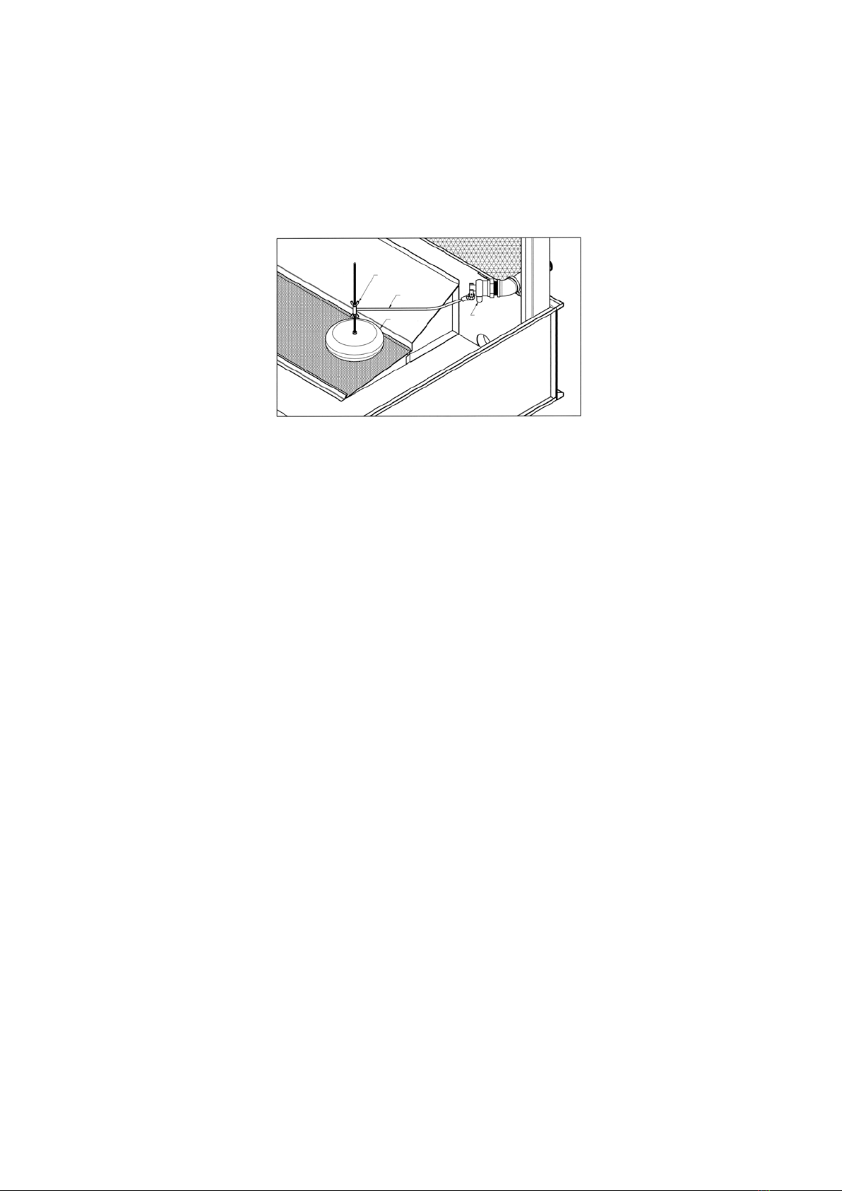
Water Make Up Valve
Amechanicaloatvalveassemblyisprovidedasstandardequipmentontheevaporativecooling
unit (unless the unit has been ordered with an optional electronic water level control package
or the unit is arranged for remote sump operation). The make up valve is easily accessible from
outside the unit through the access door or removable air inlet louver. The make up valve is a
bronzevalveconnectedtoaoatarmassemblyandisactivatedbyalargefoamlledplastic
oat.Theoatismountedonanallthreadrodheldinplacebywingnuts.Thewaterlevelinthe
basinisadjustedbyrepositioningtheoatandallthreadusingthewingnuts.RefertoFigure12
for details.
Figure 12 – Mechanical Water Make Up Valve
The make up valve assembly should be inspected monthly and adjusted as required. The valve
should be inspected annually for leakage and if necessary, the valve seat should be replaced.
The make up water pressure should be maintained between 140 and 340 kPa.
Drift Eliminators
Check the drift eliminators quarterly to make sure the drift eliminators are still in the correct
position and not clogged by any debris.
If required after inspection, drift eliminators must be removed, cleaned and reinstalled correctly.
On forced draft models, the worker must use personal precautions and adequate safety
measures against the risk of a fall, in accordance with local regulations. Remove one or two
eliminatorsectionsfromthetopoftheunit,protectthellbyuseofahardboardbeforeentering
theunitandwalkingonthell.Neverwalkontheeliminators!Oncestandingonthell,the
remaining drift eliminators can be removed.
On induced draft models, lifting handles are provided along the top layer of eliminators. Remove
oneortwoeliminatorsections,protectthellbyuseofahardboardbeforeenteringtheunitand
walkingonthell.Neverwalkontheeliminators!Oncestandingonthell,theremainingdrift
eliminators can be easily removed through the access door.
Pressurized Water Distribution Systems
AllEVAPCOcoolingtowersaresuppliedwithwideoricewaterdiffusers.Thewaterdistribution
system should be checked monthly to make sure it is operating properly. Always check the spray
system with the pump on and the fans off (locked and tagged out).
On forced draft units (LSTE, LPT and PMTQ models), remove one or two eliminator sections from
the top of the unit and observe the operation of the water distribution system.
On induced draft units (AT and UAT models), lifting handles are provided on several sections of
eliminators within reach of the access door. Eliminators can be easily removed from outside of
the unit to observe the water distribution system. The diffusers are essentially non-clogging and
should seldom need cleaning or maintenance.
FLOAT BALL MAKE-UP VALVE
FLOAT ARM
ADJUSTMENT
WINGNUTS
16
If the water diffusers are not functioning properly, in most cases it is a sign that the suction strainer
has not been working properly and that foreign matter or dirt has accumulated in the water
distribution pipes. The nozzles can be cleared by taking a small pointed probe and moving it back
and forth in the diffuser opening, with the pump(s) running and the cooling load and fan(s) off.
Ifanextremebuildupofdirtorforeignmatteroccurs,removetheendcapineachbranchtoush
the debris from the header pipe. The spray branches and header can be removed for cleaning,
but should only be done if absolutely necessary.
After the water distribution system has been cleaned, the suction strainer should be checked
to make sure it is in good operating condition and positioned properly so that cavitation or air
entrapment does not occur.
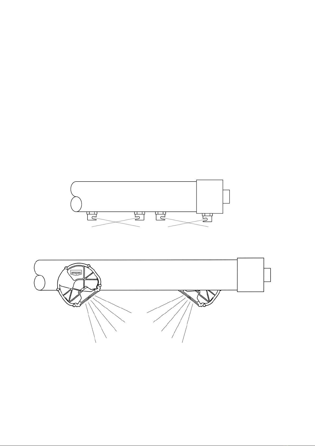
When inspecting and cleaning the water distribution system, always check that the orientation
of the water diffusers is correct as shown below for LPT and LSTE models in Figure 13 and as
shown in Figure 14 for AT/UAT and PMTQ models. The top of the EVAPCO logo on the nozzle is
parallel with the top of the water distribution pipe.
Bleed-Off Valve
Thebleed-offvalve,whetherfactoryoreldinstalled,mustbecheckedweeklytomake
sure it is functioning and set properly. Keep the bleed-off valve wide open unless it has
been determined that it can be set partially open without causing scaling or corrosion
Figure 13 – LSTE / LPT Water Distribution
Figure 14 – AT / UAT / PMTQ Water Distribution

17
Water Treatment and Water Chemistry
Proper water treatment is an essential part of the maintenance required for evaporative cooling
equipment. A well designed and consistently implemented water treatment program will help to
ensureefcientsystemoperationwhilemaximizingtheequipment’sservicelife.Aqualiedwater
treatmentcompanyshoulddesignasitespecicwatertreatmentprotocolbasedonequipment
(including all metallurgies in the cooling system), location, makeup water quality, and usage.
Bleed or Blowdown
Evaporative cooling equipment rejects heat by evaporating a portion of the recirculated water into
the atmosphere as warm, saturated discharge air. As the pure water evaporates it leaves behind
the impurities found in the system’s makeup water and any accumulated airborne contaminants.
These impurities and contaminants, which continue to recirculate in the system, must be controlled
to avoid excessive concentration which can lead to corrosion, scale, or biological fouling.
Evaporative cooling equipment requires a bleed or blowdown line, located on the discharge
side of the recirculating pump, to remove concentrated (cycled up) water from the system.
EVAPCOrecommendsanautomatedconductivitycontrollertomaximizethewaterefciencyof
your system. Based on recommendations from the water treatment company, the conductivity
controller should open and close a motorized ball or solenoid valve to maintain the conductivity
of the recirculating water. If a manual valve is used to control the rate of bleed it should be set to
maintain the conductivity of the recirculating water during periods of peak load at the maximum level
recommended by the water treatment company
Galvanized Steel – Passivation
‘White Rust’ is a premature failure of the protective zinc layer on hot dip or mill galvanized steel
which can occur as a result of improper water treatment control during the start-up of new galvanized
equipment. The initial commissioning and passivation period is a critical time for maximizing the
servicelifeofgalvanizedequipment.EVAPCOrecommendsthatthesitespecicwatertreatment
protocol includes a passivation procedure which details water chemistry, any necessary chemical
addition,andvisualinspectionsduringtherstsix(6)totwelve(12)weeksofoperation.Duringthis
passivation period, recirculating water pH should be maintained above 7.0 and below 8.0 at all times.
Since elevated temperatures have a harmful effect on the passivation process, the new galvanized
equipment should be run without load for as much of the passivation period as is practical.
The following water chemistry promotes the formation of white rust and should be avoided during
the passivation period:
1. pH values in the recirculating water greater than 8.3.
2. Calcium hardness (as CaCO3) less than 50 ppm in the recirculating water.
3. Anions of chlorides or sulfates greater than 250 ppm in the recirculating water.
4. Alkalinity greater than 300 ppm in the recirculating water regardless of pH value.
Changes in water chemistry control may be considered after the passivation process is complete
as evidenced by the galvanized surfaces taking on a dull gray color. Any changes to the
treatment program or control limits should be made slowly, in stages while documenting the
impact of the changes on the passivated zinc surfaces.
• Operating galvanized evaporative cooling equipment with a water pH below 6.0 for any
period may cause removal of the protective zinc coating.
• Operating galvanized evaporative cooling equipment with a water pH above 9.0 for any
period may destabilize the passivated surface and create white rust.
• Re-passivation may be required at any time in the service life of the equipment if an upset
condition occurs which destabilizes the passivated zinc surface.
For more information on passivation and white rust, please request a copy of EVAPCO’s
Engineering Bulletin 36.
18
Water Chemistry Parameters
The water treatment program designed for evaporative cooling equipment must be compatible
with the unit’s materials of construction, as well as other equipment and piping used in the
system.Controlofcorrosionandscalewillbeverydifcultiftherecirculatingwaterchemistryis
not consistently maintained within the ranges noted in Table 4. In mixed metallurgy systems, the
water treatment program should be designed to ensure protection of all the components used in
the cooling water loop.
TABLE 4 – Recommended Water Chemistry Guidelines
Property Z-725
Galvanized Steel
Type 304
Stainless Steel
Type 316
Stainless Steel
pH 7.0–8.8 6.0–9.5 6.0–9.5
pH During Passivation 7.0–8.0 N/A N/A
Total Suspended Solids (ppm)* <25 <25 <25
Conductivity (Micro-Siemens/cm) ** <2,400 <4,000 <5,000
Alkalinity as CaCO3(ppm) 75 - 400 <600 <600
Calcium Hardness CaCO3(ppm) 50 - 500 <600 <600
ChloridesasClˉ(ppm)*** <300 <500 <2,000
Silica (ppm) < 150 < 150 < 150
Total Bacteria (cfu/ml) <10,000 <10,000 <10,000
* Based on standard EVAPAK® ll
** Based on clean metal surfaces. Accumulations of dirt, deposits, or sludge will increase corrosion potential
*** Basedonmaximumcoiluidtemperaturesbelow49°C
If a chemical water treatment program is used, all chemicals selected must be compatible with the unit’s
materials of construction as well as other equipment and piping used in the system. Chemicals should
be fed through automatic feed equipment to a point which ensures proper control and mixing prior to
reaching the evaporative cooling equipment. Chemicals should never be batch fed directly into the basin
of the evaporative cooling equipment.
Evapco does not recommend the routine use of acid due to the destructive consequences of improper
feeding;however,ifacidisusedaspartofthesitespecictreatmentprotocol,itshouldbepre-diluted
prior to introduction into the cooling water and fed by automated equipment to an area of the system
which ensures adequate mixing. The location of the pH probe and acid feed line should be designed
in conjunction with the automated feedback control to ensure that proper pH levels are consistently
maintained throughout the cooling system. The automated system should be capable of storing and
reporting operational data including pH reading and chemical feed pump activity. Automated pH control
systems require frequent calibration to ensure proper operation and to protect the unit from increased
corrosion potential.
The use of acids for cleaning should also be avoided. If acid cleaning is required, extreme caution must
be exercised and only inhibited acids recommended for use with the unit’s materials of construction
should be used. Any cleaning protocol, which includes the use of an acid, shall include a written
procedureforneutralizingandushingtheevaporativecoolingsystematthecompletionofthecleaning.
Control of Biological Contamination
Evaporative cooling equipment should be inspected regularly to ensure good microbiological control.
Inspections should include both monitoring of microbial populations via culturing techniques and visual
inspections for evidence of biofouling.
Poormicrobiologicalcontrolcanresultinlossofheattransferefciency,increasecorrosionpotential,and
increasetheriskofpathogenssuchasthosethatcauseLegionnaires’disease.Thesitespecicwater
treatment protocol should include procedures for routine operation, startup after a shut-down period, and

19
system lay-up, if applicable. If excessive microbiological contamination is detected, a more aggressive
mechanical cleaning and/or water treatment program should be undertaken.
It is important that all internal surfaces, particularly the basin, be kept clean of accumulated dirt and
sludge. Additionally, drift eliminators should be inspected and maintained in good operating condition.
Gray Water and Reclaimed Water
The use of water reclaimed from another process as a source of makeup water for evaporative
cooling equipment can be considered as long as the resultant recirculating water chemistry
conforms to the parameters noted in Table 4. It should be noted that using water reclaimed from
other processes may increase the potential of corrosion, microbiological fouling, or scale formation.
Gray water or reclaimed water should be avoided unless all of the associated risks are understood
anddocumentedaspartofthesitespecictreatmentplan.
Air Contamination
Evaporative cooling equipment draws in air as part of normal operation and can scrub particulates
outoftheair.Donotlocatetheunitnexttosmokestacks,dischargeducts,vents,uegas
exhausts, etc. because the unit will draw in these fumes which may lead to accelerated corrosion
or deposition potential within the unit. Additionally, it is important to locate the unit away from
the building’s fresh air intakes to prevent any drift, biological activity, or other unit discharge from
entering the building’s air system.
Stainless Steel
Stainless steel is the most cost effective material of construction available to extend the life of an
evaporative cooling unit.
The stainless steel sheet material utilized by EVAPCO is Type 304L and Type 316L with a
No.2Bunpolishednish.Type304Lstainlesssteelisabasicchromium-nickelausteniticstainless
steel and is suitable for a wide range of applications. It is readily available throughout the world
and is easy to form during the fabrication process. Type 316L stainless steel offers more corrosion
resistance than Type 304L due to the addition of molybdenum and a higher nickel content, which
provides greater resistance to pitting and crevice corrosion in the presence of chlorides. As a
result, Type 316L stainless steel is desirable in heavy industrial, marine environments and where
make up water quality requires it.
Stainlesssteelprovidesitssuperiorcorrosionresistancebydevelopingasurfacelmof
chromium oxide during the manufacturing process. In order to ensure maximum corrosion
protection, stainless steel must be kept clean and have an adequate supply of oxygen to combine
with the chromium in the stainless steel to form “chromium-oxide”, a protective passivation layer.
The protective layer of chromium-oxide develops during routine exposure to the oxygen content
in the atmosphere. This occurs during the milling process and continuously as the stainless is
formedandshapedforitsnaluse.

20
Maintaining the Appearance of Stainless Steel
It is a common misconception that stainless steel is stain and rust proof, making surface maintenance
not required at all. This is simply not true. Like mill galvanized steel, stainless steel is most effective
whenkeptclean.Thisisespeciallytruewhenlocatedinatmosphereswithchloridesalts,suldesor
other rusting metals. In these environments, stainless steel can discolor, rust or corrode.
Once the unit arrives at the job site, the most effective way of maintaining the stainless steel
nishistokeepitclean!Alwaysprotectthestainlesssteelcomponentsfromcontamination
with steel or other rusting materials. The most common ways of contamination are due to
grinding and welding in the vicinity of the stainless steel tower or steel particles collected in the
piping connecting the tower to the cooling system. At a minimum, the unit should be washed
down annually to reduce residual dirt or surface deposits on the stainless steel. In addition, this
wash down will keep the stainless steel components free from the corrosive elements in the
atmosphereincludingchloridesandsuldeswhicharedamagingtostainlesssteel.
Cleaning of Stainless Steel
Routine Maintenance – Mild Cleaning
Simple pressure washing (of sheet metal components only), using household cleaners,
detergents or ammonia annually (more frequently in marine or industrial environments) will
helpmaintainthenishandkeepitfreeofatmosphericcontaminants.
Minor Surface Dirt – Mildly Aggressive Cleaning
Use of a sponge or bristle brush with a non-abrasive cleaner is recommended. After
cleaning, rinse with warm water from a hose or pressure washer. Towel dry cleaned area
and coat area with a high quality wax to provide extra protection.
More Aggressive Cleaning – Removal of Fingerprints or Grease
Repeat processes 1 and 2, then use a hydro-carbon solvent like Acetone or alcohol. As
with any hydro-carbon solvent, caution must be taken when using the product. Do not use
inconnedspacesorwhilesmoking.Keepsolventsoutofcontactwithhandsandskin.
Household glass cleaner, Spic n’ Span are other options for cleaners. After cleaning, towel
dry and apply a coat of high quality wax for extra protection.
Aggressive Cleaning – Removing Stains or Light Rust
If iron contamination or surface staining is suspected, immediately remove the stain or rust using
a chrome, brass or silver cleaner. The use of mild non-scratching creams and polishes are also
recommended. When the cleaning procedure is complete; use a high quality wax for extra protection.
Most Aggressive Cleaning – Removing Heavy Rust Deposits, Iron Contamination,
Spot Weld Discoloration and Weld Spatter using Acid
First try processes 1 through 4. If the stain or rust is not removed, the following should be
used as a last resort. Rinse the surface with hot water. Use a saturated solution of oxalic
or phosphoric acid (10 to 15% acid solution). This should be applied with a soft cloth and
allowedtostandforafewminutes–donotrub.Thisacidshouldetchouttheironparticles.
Follow this with an ammonia and water rinse. Rinse the surface again with hot water; coat
withahighqualitywaxforaddedprotection.Useextremecautionwhenworkingwithacids!
Synthetic rubber gloves should be used, goggles and aprons are advisable.
DO NOT USE THIS METHOD IF THE UNIT HAS GALVANIZED STEEL COMPONENTS.
As a minimum, these guidelines should be followed to maintain and clean the stainless steel unit.
When cleaning stainless steel, NEVER use coarse abrasives or steel wool, NEVER clean with
mineral acids and NEVER leave stainless in contact with iron or carbon steel.
For more information on cleaning stainless steel, please request a copy of EVAPCO’S Engineering
Bulletin 40.
Other manuals for AT Series
1
This manual suits for next models
42
Table of contents
Other EVAPCO Accessories manuals


Popular Accessories manuals by other brands


WAC Lighting
WAC Lighting MS-120 Installation instruction

Halfords
Halfords 456686 instructions

VPG
VPG VanWeigh Installation, Setup and Calibration Manual

Minebea Intec
Minebea Intec Maxxis 5 Count PR 5900/82 operating instructions

Optex
Optex OAM-DUAL T Operation manual

Jenile
Jenile CBM14 instruction manual

Flavor Burst
Flavor Burst CTP 80SS-INT Operation manual supplement

Alarmcom
Alarmcom ADC-IS-300-LP installation guide

COOK Medical
COOK Medical MINC K-MINC-1000 user manual

PLX Devices
PLX Devices Legion 5.500mAh user manual

Silvercrest
Silvercrest HG04522A-US-TX manual

Baicells
Baicells Nova-233 G2 Installation Installation