EVAPCO ESW Series User manual
Rigging and
Assembly Instructions
ESW CLOSED
CIRCUIT COOLERS
Bulletin 145-E Metric
EVAPCO, INC. (World Headquarters) P.O. Box 1300, Westminster, Maryland 21158 USA
Phone (410) 756-2600 Fax (410) 756-6450
EVAPCO products are manufactured worldwide:
EVAPCO Europe
Industrieterrein Oost 4010
3700 Tongeren, Belgium
Phone: (32) 12 395029
Fax: (32) 12 238527
EVAPCO Europe S.r.l.
Via Ciro Menotti 10
20017 Passirana di Rho (MI), Italy
Phone: (39) 02 9399041
Fax: (39) 02 93500840
EVAPCO Europe GmbH
Bovert 22
D-40670 Meerbusch, Germany
Phone: (49) 2159-6956-0
Fax: (49) 2159-6956-11
FOR EVAPCO AUTHORIZED PARTS AND SERVICE, CONTACT YOUR LOCAL
MR. GOODTOWER SERVICE PROVIDER OR THE EVAPCO PLANT NEAREST YOU.
2
ESW Closed Circuit Coolers
Method of Shipment
ESW models are shipped with the top section(s) separate
from the bottom section(s). These sections have mating
flanges and will join together in a waterproof joint when
sealed and bolted together as described in the following
instructions. Miscellaneous items, such as sealer tape, bolt
sets and any other required materials, are packaged and
placed inside th0e pan for shipment.
Storage
Do not place tarps or other coverings over the top of the
units if the units are to be stored before installation.
Excessive heat can build up if the units are covered,
causing possible damage to the PVC eliminators, PVC
louvers, or PVC fill. For extended storage beyond six
months, rotate the fan and fan motor shaft(s) monthly.
Also, the fan shaft bearings should be purged and
regreased prior to start-up.
Structural Steel Support
Two structural “I” beams running the length of the unit are
all that is required for support of the units. These beams
should be located underneath the outer flanges of the unit
(see Figure 1). Mounting holes, 19 mm in diameter, are
located in the bottom flange of the unit to provide for bolting
it to the structural steel (see certified print for exact bolt hole
location). Bolt the bottom section to the steel support before
rigging the top section.
Beams should be sized in accordance with accepted
structural practices. Maximum deflection of the beam under
the unit to be 1/360 of the unit length, not to exceed 13 mm.
Deflection may be calculated by using 55% of the operating
weight as a uniform load on each beam (see certified print
for operating weight).
The supporting “I” beams should be level before setting the
unit. Do not level the unit by shimming between the bottom
flange and the beams as this will not provide proper
longitudinal support.
Support beams and anchor bolts are to be furnished by
others. Always refer to certified print for unit weights,
dimensions and technical data.
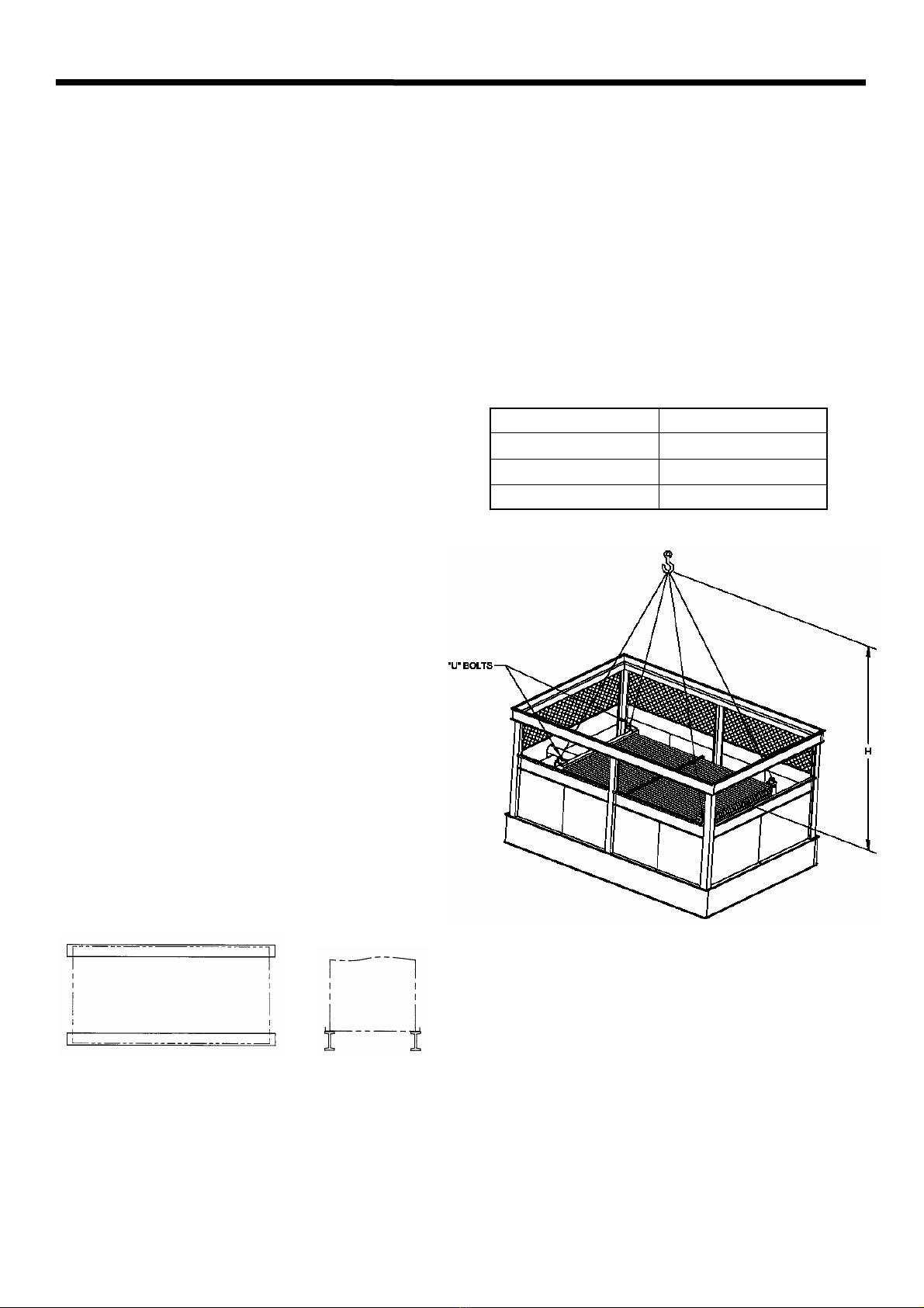
Figure 1 - Structural Steel Support.
Rigging Bottom Section
Lifting devices are located in the upper corners of the coil as
shown in Figure 2. The hook of the crane must be a
minimum dimension of “H” above the top of the coil to
prevent undue strain on the lifting devices.
See Table 1 for the minimum “H” dimension. These lifting
devices should not be used for extended lifts or where any
hazard exists unless safety slings are employed under the
section. (See “Extended Lifts” on page 4 for proper
arrangement.) Bolt the bottom section to the steel support
before rigging the top section.
Table 1 - Minimum H Dimension for Bottom Sections.
Figure 2 - ESW Bottom Section
Basin Section Length - m MIN. H (Above Coil) - m
2,7 2,1
3,6 3,0
5,4 4,2
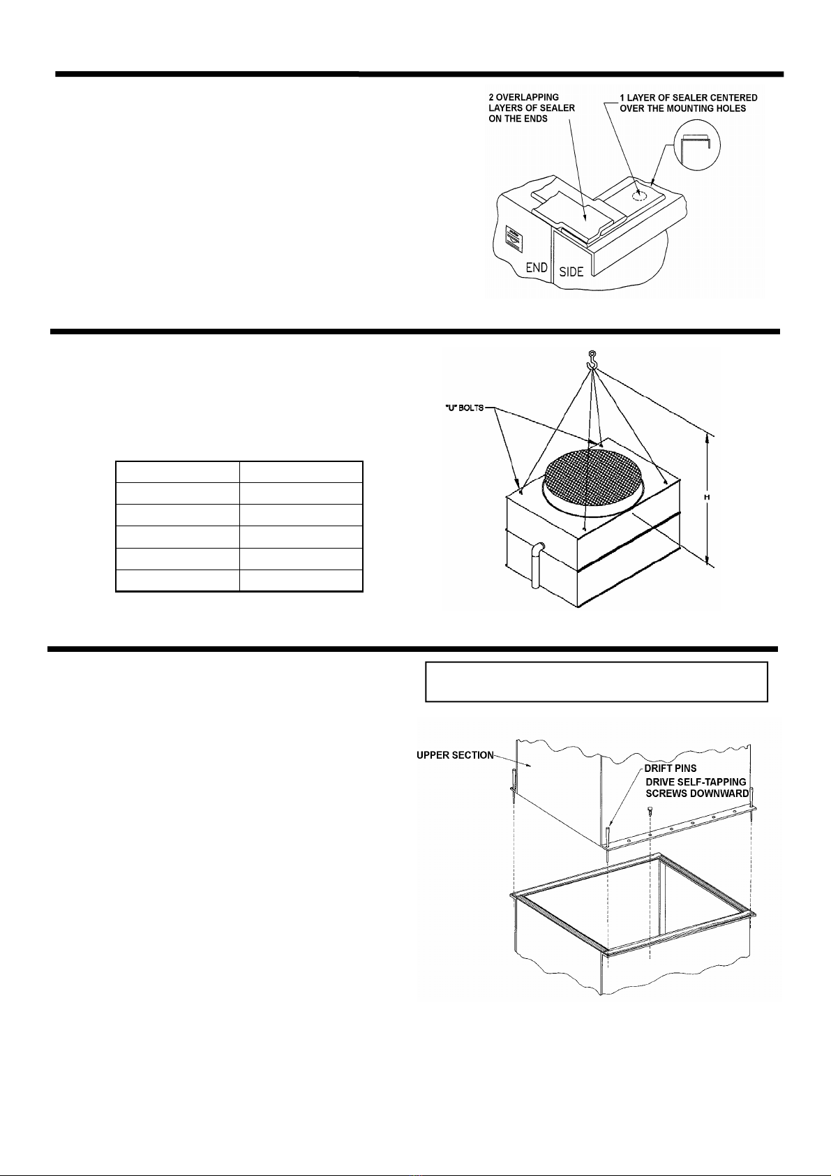
Applying Sealer Tape
Once the bottom section has been set on the supporting steel and
bolted in place, the top flanges should be wiped down to remove any
dirt or moisture. Sealer tape should be placed over the mounting hole
centerline on the side flanges. Apply two strips of sealer tape, one
partially overlapping the other, on the end flanges.
The sealer tape should overlap on the corners as shown in Figure 3.
Do not splice the sealer tape along the end flanges and preferably not
on the side flanges if it can be avoided. Always remove the paper
backing from the sealer tape.
Figure 3 - Proper Sealer Tape Application
Top Section
“U” bolts are provided in the four corners of the top section
for lifting and final positioning (See Figure 4). The hook of
the crane must be a minimum dimension “H” above the top
section being lifted to prevent undue strain on the “U” bolts.
See Table 2 for the minimum “H” dimension.
Table 2 -Minimum H Dimension for Top Sections.
UNIT NO. MIN. H - m
ESW 72 models 2,7
ESW 96 models 3,6
ESW 142 models 5,1
ESW 144 models 3,6
ESW 216 models 5,1
Figure 4 - ESW Top Section.
ESW Closed Circuit Coolers
Assembly of the Top Section to the Bottom
Section
Before assembling the top section to the bottom section,
remove any loose parts shipped in the pan.
Wipe the flanges on the bottom of the top section. Check to
see that the water distribution connection on the top section is
in the correct position relative to the bottom section (see
certified unit drawing). Units are also provided with match
markings on each section (i.e. A1 of bottom section should
match up with A1 of top section).
Lower the top section to within several inches of the bottom
section making sure the two sections do not touch and the
sealer is not disturbed. Using suitably sized drift pins to
assure proper alignment, lower the top section down onto the
bottom section. Fasten all four corners. Install the remaining
fasteners, working from the corners toward the center, using
drift pins to align the holes. Fasteners must be installed in
every hole on the side flange. None are required on the end
flanges. Galvanized units will use 5/16” self tapping screws
and stainless steel units will use 8 mm nuts, bolts and
washers. See Figure 5.
Note: 8 mm stainless steel nuts, bolts and washers are
used on stainless steel models.
Figure 5 - Mating Upper Section to Bottom Section.
3

4
Extended Lifts
Important: The lifting devices and “U” bolts should be
used for final positioning only and for lifting where no
danger exists. If they are used for extended lifts, safety
slings should be provided under the sections.
The preferred method for extended lifts is to use slings
under the unit (see Figures 5, 6, 7). Spreader bars should
always be used between the cables at the top of the section
to prevent damage to the upper flanges or fan cylinders.
Safety slings and skids should be removed before final positioning of the unit.
ESW Closed Circuit Coolers
Figure 8 - Proper Rigging Method for Extended Lifts. (5,4 m long units)
Figure 6 -ESW Top Section
Figure 7 - Proper Rigging Method for Extended Lifts. (2,7 & 3,6 m long units)

Figure 9 - Attaching Fan Screen to Cylinder
5
ESW Closed Circuit Coolers
Mounting Fan Screens
3,6 m Wide Models
In certain situations some units may be shipped with the fan
screens in the basin. Under these circumstances, use the
following procedures to mount the fan screen on the discharge
cylinder.
WARNING: DO NOT WALK ON THE FAN SCREENS AT
ANY TIME!
1. Place both halves of the fan screen on top of the
discharge cylinder. Each half will be tagged to match
markings on the cylinder. Align the eyelets of the fan
screen with the holes tha\t can be found on the
perimeter of the discharge cylinder.
2. At each hole, attach the fan screen to the discharge
cylinder as shown in Figure 9.
3. Join the two screen halves with wire clips (Figure 10).
There should be 3 wire clips on each side of the fan
screen. Space the wire clips evenly across the
radius of the fan screen as shown in Figure 11.
Figure 10 - \\\Wire Clip Arrangement
Figure 11- Wire Clip Spacing
Mounting Fan Screens
3,6 m Wide by 5,4 m Long Models
On these models, the fan screen is supported from underneath
by an “X” shaped support frame.
1. Set the support frame across the top of the discharge
cylinder (See Figure 12).
2. Place both halves of the fan screen on top of the support
frame. Each half will be tagged to match markings on the
cylinder. Align the eyelets of the fan screen with the holes
on the cylinder perimeter.
3. Join the two screen halves with wire clips (See Figure 10).
There should be four clips on either side of the fan screen.
Space them evenly as shown in Figure 11.
4. At each hole, attach the fan screen to the discharge
cylinder as shown in Figure 9. At the four points where the
support frame meets the cylinder, bolt the support frame to
the cylinder together with the fan screen.
Figure 12 - Support Frame Installation
Other manuals for ESW Series
1
This manual suits for next models
5
Table of contents
Other EVAPCO Accessories manuals


