EVAPCO ESW4 User manual
Rigging and
Assembly Instructions
ESW4 CLOSE CIRCUIT COOLERS
Visit EVAPCO’s Website at: evapco.com
EVAPCO...SPECIALISTS IN HEAT TRANSFER PRODUCTS AND SERVICES.
EVAPCO Products are Manufactured Wordwide
Bulletin ESW419RIG
EVAPCO, Inc. — World H adquart rs & R s arch/D v lopm nt C nt r
P.O. Box 1300 • Westminster, M 21158 USA
410-756-2600 p • [email protected] • evapco.com
EVAPCO, Inc.
World H adquart rs
P.O. Box 1300
Westminster, M 21158 USA
410-756-2600 p | 410-756-6450 f
Asia/Pacific
EVAPCO Asia/Pacific H adquart rs
1159 Luoning Road
Baoshan Industrial Zone
Shanghai 200949, P.R. China
(86) 21-6687-7786 p | (86) 21-6687-7008 f
Europ
EVAPCO Europ BVBA
Europ an H adquart rs
Heersterveldweg 19
Industrieterrein Oost
3700 Tongeren, Belgium
(32) 12-395029 p | (32) 12-238527 f
EVAPCO East
5151 Allendale Lane
Taneytown, M 21787 USA
410-756-2600 p | 410-756-6450 f
EVAPCO East
Key Building
Taneytown, M USA
410-756-2600 p
EVAPCO Midw st
Greenup, IL USA
217-923-3431 p
evapcomw@evapcomw.com
EVAPCO W st
Madera, CA USA
559-673-2207 p
EVAPCO Iowa
Lake View, IA USA
712-657-3223 p
EVAPCO Iowa
Sales & Engineering
Medford, MN USA
507-446-8005 p
EVAPCO N wton
Newton, IL USA
618-783-3433 p
evapcomw@evapcomw.com
EVAPCOLD
Greenup, IL USA
217-923-3431 p
evapcomw@evapcomw.com
EVAPCO-BLCT Dry Cooling, Inc.
Bridgewater, NJ 08807 USA
908-379-2665 p
EVAPCO-BLCT Dry Cooling, Inc.
Littleton, CO 80127 USA
908-379-2665 p
EVAPCO Pow r México S. d R.L. d C.V.
Calle Iglesia No. 2, Torre E
Tizapan San Ángel, el. Álvaro Obregón
Ciudad de México, .F. México 01090
+52 (55) 8421-9260 p
R frig ration V ss ls & Syst ms Corporation
A wholl owned subsidiar of EVAPCO, Inc.
Bryan, TX USA
979-778-0095 p
EvapT ch, Inc.
A wholl owned subsidiar of EVAPCO, Inc.
Edwardsville, KS USA
913-322-5165 p
Tow r Compon nts, Inc.
A wholl owned subsidiar of EVAPCO, Inc.
Ramseur, NC USA
336-824-2102 p
EVAPCO Alcoil, Inc.
A wholl owned subsidiar of EVAPCO, Inc.
York, PA USA
717-347-7500 p
EVAPCO Europ , S.r.l.
Milan, Italy
(39) 02-939-9041 p
EVAPCO Europ , S.r.l.
Sondrio, Italy
EVAPCO Europ GmbH
Meerbusch, Germany
(49) 2159 6956 18 p
EVAPCO Air Solutions
A wholl owned subsidiar of EVAPCO, Inc.
Aabybro, enmark
(45) 9824 4999 p
EVAPCO Air Solutions GmbH
Garbsen, Germany
(49) 5137 93875-0 p
Evap Egypt Engin ring Industri s Co.
A licensed manufacturer of EVAPCO, Inc.
Nasr City, Cairo, Egypt
2 02 24022866/2 02 24044997 p
primacool@link.net / shady@primacool.net
EVAPCO Middl East DMCC
ubai, United Arab Emirates
+971 4 448 7242 p
EVAPCO S.A. (Pty.) Ltd.
A licensed manufacturer of EVAPCO, Inc.
Isando 1600, Republic of South Africa
(27) 11-392-6630 p
EVAPCO (Shanghai) R frig ration Equipm nt Co., Ltd.
Baoshan Industrial Zone Shanghai, P.R. China
(86) 21-6687-7786 p
B ijing EVAPCO R frig ration Equipm nt Co., Ltd.
Huairou istrict Beijing, P.R. China
010-6166-7238 p
EVAPCO Air Cooling Syst ms (Jiaxing) Company, Ltd.
Building 10, 1133 Taoyuan Road,
Jiaxing, Zhejiang, China
(86) 573 83119379 p
info@evapcoacs.cn
EVAPCO Australia (Pty.) Ltd.
Riverstone NSW 2765, Australia
(61) 2 9627-3322 p
EvapT ch Asia Pacific Sdn. Bhd
A wholl owned subsidiar of EvapTech, Inc.
Puchong, Selangor, Malaysia
(60-3) 8070-7255 p
North Am rica
South Am rica
EVAPCO Brasil
Equipamentos Industriais Ltda.
Al. Vênus, 151 – CEP: 13347-659
Indaiatuba –São Paulo – Brasil
(55+11) 5681-2000 p
Fan T chnology R sourc s
Cruz das Almas – Indaiatuba
São Paulo, Brasil 13308-200
55 (11) 4025-1670 p
fantr@fantr.com
2
ESW4 Closed Circuit Coolers
Method of Shipment
ESW4 models are shipped with the top section(s) separate from the bottom section(s). These sections have mating flanges and
will join together in a waterproof joint when sealed and bolted together as described in the following instructions. Miscellaneous
items, such as sealer tape, hardware and any other required materials, are packaged and placed inside the pan for shipment.
For 8.5’ (2.6m) wide units, the motors and drives are factory aligned and then shipped loose inside the basin section for mounting
during installation. Refer to the “External Motor Installation” section in this bulletin.
Storage
o not place tarps or other coverings over the top of the units if the units are to be stored before installation. Excessive heat can
build up if the units are covered, causing possible damage to the PVC eliminators, louvers or fill. For extended storage beyond six
months rotate the fan and fan motor shaft(s) monthly. Also, the fan shaft bearings should be purged and regreased prior to start-up.
International Building Code Provisions
The International Building Code (IBC) is a comprehensive set of regulations addressing the structural design and installation
requirements for building systems – including HVAC and industrial refrigeration equipment. As of June 2008, all 50 states plus
Washington .C have adopted the International Building Code. The code provisions require that evaporative cooling equipment
and all other components permanently installed on a structure must meet the same seismic design criteria as the building.
All items attached to the Evapco ESW4 Closed Circuit Cooler must be independently reviewed and isolated to meet applicable
wind and seismic loads. This includes piping, ductwork, conduit, and electrical connections. These items must be flexibly attached
to the Evapco unit so as not to transmit additional loads to the equipment as a result of seismic or wind forces.
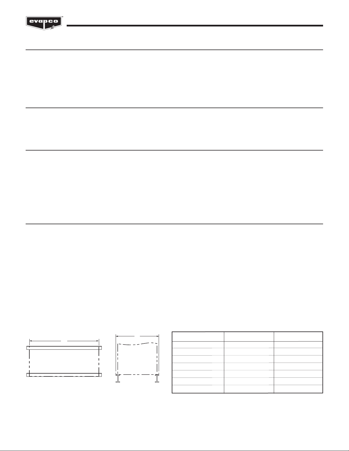
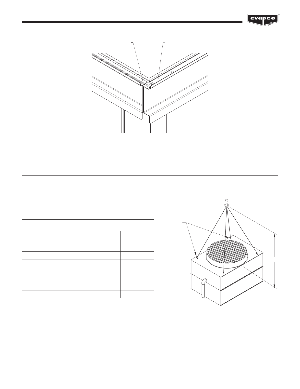
Structural Steel Support
Evapco recommends supporting the unit with two structural “I” beams that span the entire length of the unit*. These beams should
be located underneath the outer flanges of the unit. (See Figure 1). Mounting holes, 3/4” (19mm) in diameter, are located in the
bottom flange for bolting to the structural steel (see certified print for exact bolt hole location). Bolt the bottom section to the steel
support before rigging the top section.
Beams should be sized in accordance with accepted structural practices. Maximum deflection of the beam under the unit not to
exceed 1/2” (13mm). eflection may be calculated by using 55% of the operating weight as a uniform load on each beam (see
certified print for operating weight).
The supporting “I” beams should be level before setting the unit. o not level the unit by shimming between the bottom flange and
the beams as this will not provide proper longitudinal support.
Support beams and anchor bolts are to be furnished by others. Always refer to certified print for unit weights, dimensions and
technical data.
Note: Consult IBC for required steel support layout and structural design.
Figure 1A
Plan Views
Figure 1B
End Elevations
A
8.5' to 14' WIDE
MODELS
B
8.5' to 14'
WIDE
MODELS
* The Engineer of Record is ultimately responsible for the steel support design and may require additional cross beams based on loads.
Unit Footprint A B
8.5' x 6' (2.6m x 1.8m) 8' 5-1/2" (2,578mm) 5' 11-7/8" (1,826mm)
8.5' x 9' (2.6m x 2.7m) 8' 11-1/2" (2,731mm) 8' 5-1/2" (2,578mm)
8.5' x 12' (2.6m x 3.6m) 11' 11-3/4" (3,651mm) 8' 5-1/2" (2,578mm)
8.5' x 18' (2.6m x 5.5m) 18' 0" (5,486mm) 8' 5-1/2" (2,578mm)
12' x 12' (3.6m x 3.6m) 11' 11-3/4" (3,651mm) 11' 10" (3,607mm)
12' x 18' (3.6m x 5.5m) 18' 0" (5,486mm) 11' 10" (3,607mm)
14' X 22' (4.2m X 6.7m) 21' 11-3/4" (6,700mm) 13' 11-1/4" (4,250mm)
Table 1 – ESW4 Supporting Steel imensions
3
ESW4 Closed Circuit Coolers
Basin Section Length in. “H” Dim. (above lift point)
8.5' (2.6m) 7' (2.1m)
9' (2.7m) 7' (2.1m)
12' (3.6m) 10' (3m)
18' (5.5m) 12' (3.6m)
22' (6.7m) 21' (6.4m)
Table 2 – Minimum “H” imension for Basin Sections
H
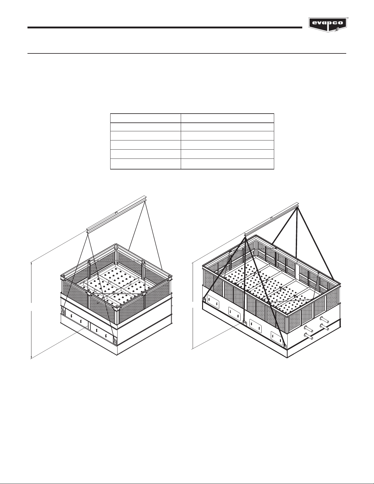
Rigging the Bottom Section: Standard Lift
Lifting devices are located in the lower corners of the unit as shown in Figures 2 and 3. The hook of the crane must be a minimum
dimension of “H” above the lift point to prevent undue strain on the lifting devices.
See Table 2 for the minimum “H” dimension. Bolt the bottom section to the steel support before rigging the top section of the unit.
The unit lifting devices should not be used for extended lifts or where any hazard exists unless safety slings are employed under
the section.
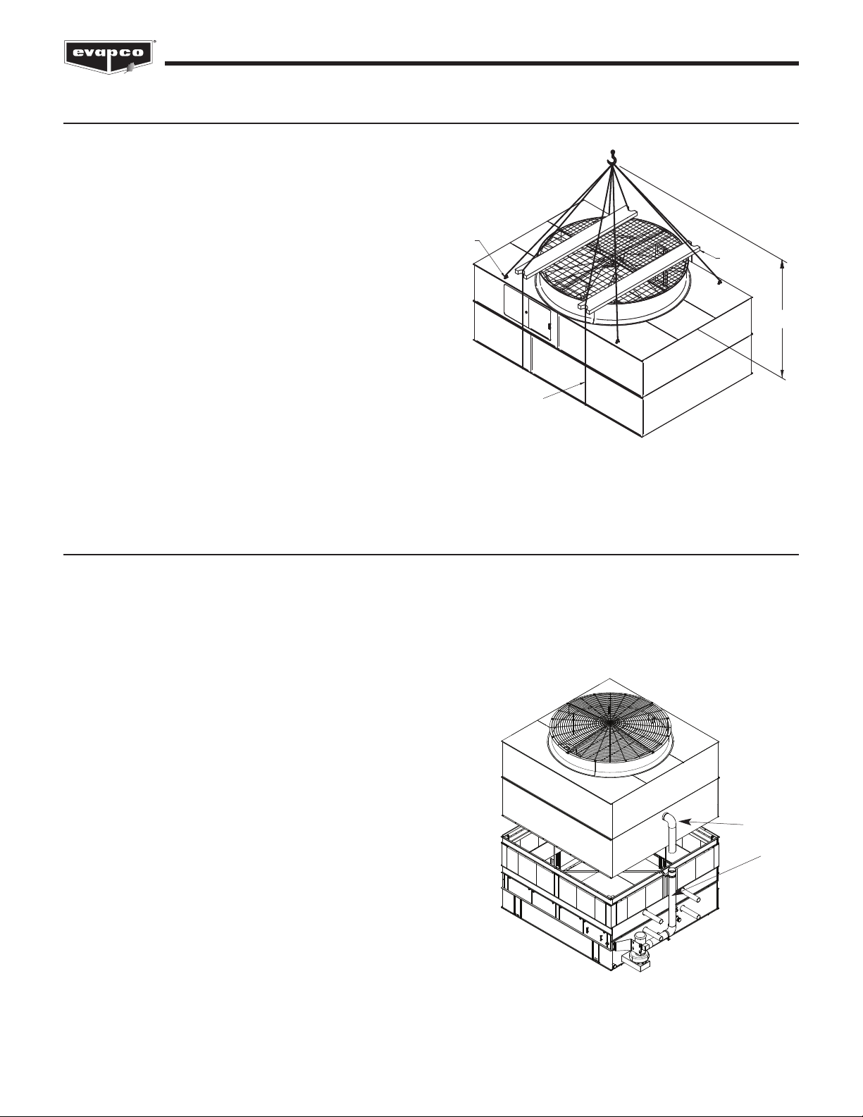
Figure 3 – ESW4 Bottom Section
18’ (5.5m) and 22’ (6.7m) 6 point rig
Important: The lifting devices should be used only for lifting where no danger exists and for final positioning of the
section. For extended lifts, safety slings should be provided under the section as described on page 4.
H
Figure 2 – ESW4 Bottom Section
4 point rig
4
ESW4 Closed Circuit Coolers
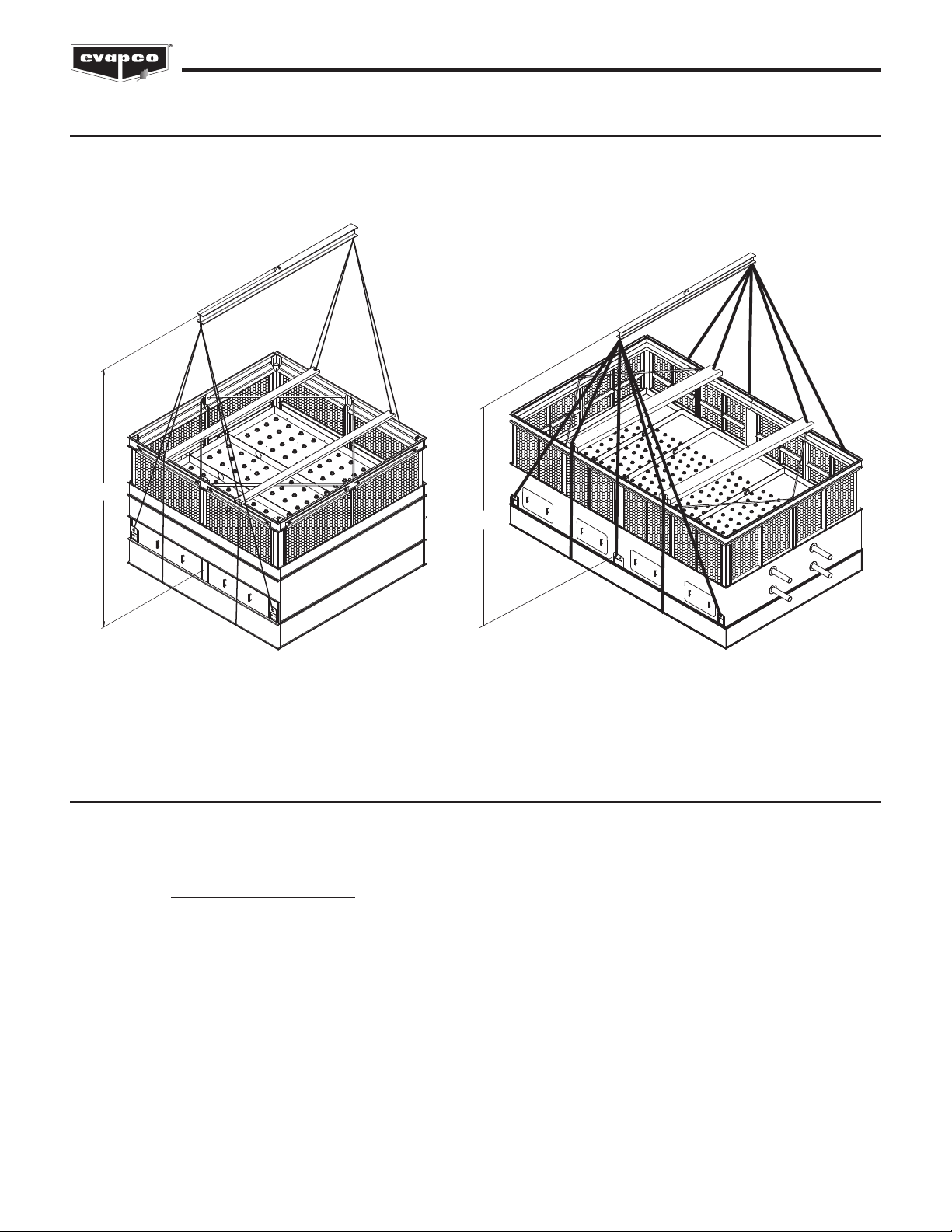
Rigging the Bottom Section: Extended Lifts
The preferred method for extended lifts is to use slings under the unit as shown in Figures 4 and 5. Spreader bars should always
be used between the cables at the top of the section to prevent damage to the upper portion of the basin. Safety slings and skids
should be removed before final positioning of the unit. See Table 2 on page 3 for minimum “H” dimensions.
Application of Sealer Tape
Once the bottom section has been set on the supporting steel and bolted in place, the top flanges should be wiped down to remove
any dirt or moisture. Sealer tape should be placed over the mounting hole centerline on the side flanges along the entire length of
all sides. Apply two strips of sealer tape, one partially overlapping the other, on the entire length of the end flanges.
The sealer tape should overlap on the corners as shown in Figure 6. o not splice the sealer tape along the end flanges and
preferably not on the side flanges if it can be avoided.
Always remove the paper backing from the sealer tape.
H
Figure 5 – Proper Rigging Method for Extended Lifts
18’ (5.5m) and 22’ (6.7m) long
H
Figure 4 – Proper Rigging Method for Extended Lifts
ESW4 Closed Circuit Coolers
5
Rigging the Top Section: Standard Lift (2-Piece Shipment)
“U” bolts are provided in the four corners of the top section for lifting and final positioning (See Figure 7). The hook of the crane
must be a minimum dimension “H” above the top of the section being lifted to prevent undue strain on the “U” bolts. See Table 3 for
the minimum “H” dimension.
H
“U” BOLTS
Figure 7 – ESW4 Top Section
Important: The “U” Bolts should be used only for lifting where no danger exists and for final positioning of the section.
For extended lifts, safety slings should be provided under the section as described on page 6.
2OVERLAPPING LAYERS
OF SEALER TAPE
ON THE ENDS
1LAYER OF SEALER TAPE
CENTERED OVER THE
MOUNTING HOLES
END SIDE
Figure 6 – Sealer Tape on Flange of Bottom Section
inumum “H” Dim.
(above fan deck)
Box Size Standard Super Low
Fan Sound Fan
8.5' x 6' (2.6m x 1.8m) 7' (2.1m) 8' (2.4m)
8.5' x 9' (2.6m x 2.7m) 9' (2.7m) 12' (3.6m)
8.5' x 12' (2.6m x 3.6m) 12' (3.6m) 12' (3.6m)
8.5' x 18' (2.6m x 5.5m) 17' (5.2m) 20' (6m)
12' x 12' (3.6m x 3.6m) 12' (3.6m) 15' (4.6m)
12' x 18' (3.6m x 5.5m) 17' (5.2m) 19' (5.8m)
14' X 22' (4.2m x 6.7m) 18' (5.5m) 18' (5.5m)
Table 3 – Minimum “H” imension for Top Sections
6
ESW4 Closed Circuit Coolers
Assembly of the Top Section to the Bottom Section
Before assembling the top section to the bottom section, remove any loose parts shipped in the pan. Apply sealer tape as shown in
Figure 6 on page 5.
Wipe the flanges on the bottom of the top section. Check to see that the water distribution connection on the top section is in the
correction position relative to the bottom section (see certified unit drawing). Units are also provided with match markings on each
section (i.e. A1 of bottom section should match up with A1 of top section).
Lower the top section to within several inches of the bottom
section making sure the two sections do not touch and the
sealer tape is not disturbed. Using suitably sized drift pins to
assure proper alignment, lower the top section down onto the
bottom section.
Place nuts and bolts in all four corner bolt holes. Then continue
to install the rest of the nuts and bolts working from the corners
toward the center. Nuts and bolts must be installed in every
hole on the side flanges and end flanges. Cut off extra sealer
tape once the section is bolted into place.
Rigging the Top Section: Extended Lifts
The preferred method for extended lifts is to use slings under
the unit as shown in Figure 8. Spreader bars should always be
used between the cables at the top of the section to prevent
damage to the upper flanges or fan cylinder. Safety slings and
skids should be removed before final positioning of the unit.
See Table 3 on page 5 for minimum “H” dimensions.
H
“U” BOLTS
SPREADER
BARS
SAFETY SLINGS
Figure 8 – Proper Rigging Method for Extended Lifts
Figure 9 – Mating Upper Section to Bottom Section.
WATER
ISTRIBUTION
CONNECTIONS
7
ESW4 Closed Circuit Coolers
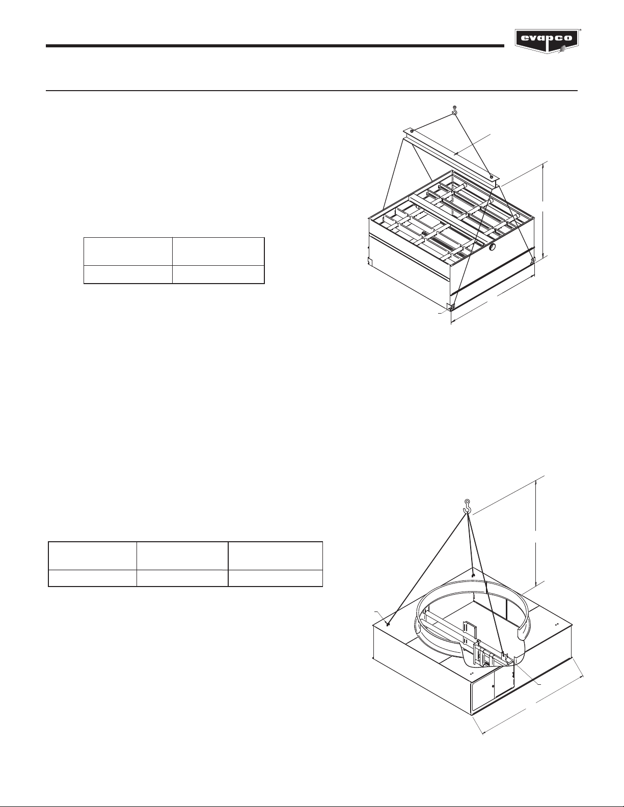
3-Section Shipments
In some cases, a unit is shipped in 3 sections (Fan, Casing and
Basin) in lieu of the standard 2 sections (Fan + Casing, and Basin).
This is often done to reduce the shipping height of each individual
section, which in turn may reduce the size of the crane required to
rig the unit.
Casing Section Rigging
All casing sections will be rigged as a four-point lift as shown in
Figure 9a.
H
L
LIFTING EAR
SPREADER BAR
Section inimum "H"
Length Dimension
14' (4.2m) 14' (4.2m)
Table 4 – Minimum “H” imension for
Four-Point Lift of Cooler Casing Sections
Figure 9a – Four-Point Rigging of Tower Casing
Section with Added Lifting Ears
H
“U” BOLTS
LIFTING
EAR
L
Fan Section Rigging
When lifting the fan section separate from the casing section, the center of gravity of the fan section is heavily biased towards the
location of the fan motor and major drive components. In order to avoid lifting the fan section at a lopsided angle, a three-point lift is
necessary.
In such a case, an additional lifting ear is provided by the factory on the mechanical bearing support assembly. The “U” bolts on the
fan deck which are located close to the fan motor are removed.
Figure 10 shows the proper three-point lifting method for the fan section. The hook of the crane must be a minimum dimension “H”
above the top of the section being lifted to prevent undue strain on the “U” bolts.
See Table 5 below for minimum “H” dimension to safely lift the fan section during a three-point lift.
Figure 10 – Three-Point Lift
Section inimum "H" inimum "H"
Length Standard Fan Dimension SLSF
14' (4.2m) 13' (4m) 13' (4m)
Table 5 – Minimum “H” imension for Three-Point Lifts

8
ESW4 Closed Circuit Coolers
Prior to lowering the fan section onto the casing section, the side flanges on the casing sections must be cleaned by the installer
and have sealer tape applied to them. The ends will need to have 2 overlapping layers of sealer tape applied to them. Follow
instructions from the “Application of Sealer Tape” section of this manual.
rift pins should be used to align the fan section with the casing section. The installer will need to attach the fan section end panels
to the casing section end panels and the fan section side panels to the casing section side panels with self-threading tappers
(galvanized units) or bolts (stainless units).
Note: Fan screen and fan screen support will be shipped loose in the event of a 3-section shipment. Both these items
need to be installed after rigging.
Assembly of the Top Section to the Bottom Section
Before securing the upper section to the bottom section, remove any loose parts shipped in the basin.
Wipe the flanges on the bottom of the upper section. Check to see that the water distribution connection on the top section is in the
correct position relative to the bottom section (see unit certified drawing). Units are also provided with match markings on each
section (i.e. A1 of bottom section should match up with A1 of top section).
Lower the upper section to within several inches of the bottom section making sure the two sections do not touch and the sealer
tape is not disturbed. Fasten all four corners. Make use of drift pins to simplify the fastening process.
Install the remaining fasteners, working from the corners towards the center. Fasteners must be installed in every hole in the side
flanges. No fasteners are required on the end flanges.
Use of Drift Pins for Final Positioning
rift pins are tools used to align holes in the flanges of the upper and lower sections of the unit prior to final fastening. By the time
drift pins are needed, the lower section of the unit has already been anchored to its support structure. The sealer tape has been
laid down on the lower section’s flanges, and the upper section is now hovering over the lower section.
A drift pin should be driven in to each of the corner bolt holes such that the upper and lower flanges are aligned as best as possible
with sideways motion restricted.
On units which are longer than 12’ (3.6m) (“L” > 12’ (3.6m)), a drift pin should be used at an intermediate pair of bolt holes in the
rigging seam to allow for proper alignment.
Notes:
Bolts can be driven upward through the mating flanges if access is restricted.
All rigging hardware is provided by EVAPCO. Drift pins are by others.
9
ESW4 Closed Circuit Coolers
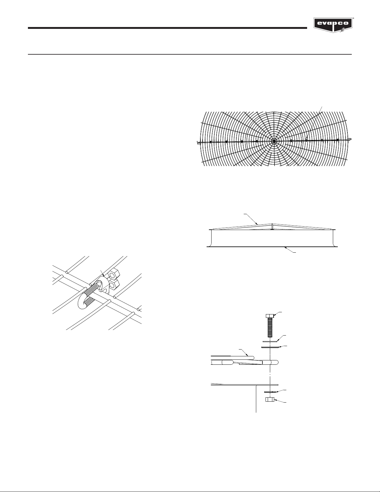
Mounting Fan Screens
12’ (3.6m) and 14’ (4.2m) wide units will be shipped with the fan screens in the basin. Under these circumstances use the following
procedures to mount the fan screen on the discharge cylinder.
WARNING: DO NOT WALK ON THE FAN SCREENS
AT ANY TI E!
1. Lay both halves of the fan screen on the ground. Join the
two screen halves with wire clips (Figure 11). There should
be 4 wire clips on each side of the fan screen for 12’
(3.6m) and 14’ (4.2m) wide units. Space the wire clips
evenly across the radius of the fan screen as shown in
Figure 12.
2. The fan screen is supported from underneath by an “X”
shaped support frame. Set the support frame across the
top of the discharge cylinder (See Figure 13), and fasten to
cylinder with 3/8” (10mm) bolts.
3. Place the fan screen on top of the support frame and
discharge cylinder. Each half will be tagged to match
markings on the cylinder. Align the eyelets of the fan
screen with the holes on the perimeter of the discharge
cylinder.
4. At each hole, attach the fan screen to the discharge
cylinder as shown in Figure 14.
5/8" (16mm) FLATWASHER
1/2" (13mm) BOLT
1/2" (13mm) FLATWASHER
FAN SCREEN
1/2" (13mm) LOCKWASHER
1/2" (13mm) HEX NUT
Figure 12 – Wire Clip Spacing
WIRE
CLIPS
FAN SCREEN
SUPPORT
FAN
CYLINDER
Figure 14 – Attaching Fan Screen to Cylinder
Figure 11 – Wire Clip Arrangement
U-BOLT
ASSEMBLY
Figure 13 – Support Frame Installation

10
ESW4 Closed Circuit Coolers
External Motor Installation (applicable to 8.5’ (2.6m) wide models only)
8.5’ (2.6m) Wide odels
1. Study Figure 15 before installing the motor base on the unit.
2. Insert the lifting device into “U” bolt Aon motor base B.
3. Lift the motor base and insert the pivot pin Cdown into
hole Eand pivot pin Finto hole D.
4. Install washer and nut (do not overtighten) on pivot pins.
Install jam nut on pivot pin C.
5. Insert “J” bolts Ginto holes H. Install flat washers and
cotter pins. Place nuts and washers on threaded portion of
“J” bolts. These will be behind the motor base installed in
the next step.
6. Insert “J” bolts into holes Jin the motor base. Install flat
washers, lock washer and nuts. Remove lifting device from
the “U” bolt on the motor base. Position motor base toward
casing of unit for belt installation.
7. Install Powerband belt K(Figure 15) around fan sheave
and motor sheave. Tighten belt by adjusting nuts on “J”
bolts. o not over tighten the belts. The center of the belt
should deflect approximately 3/4” (19mm) with moderate
hand pressure.
8. Measure to see that the top and bottom of the motor base
are the same distance out from the casing of the unit. This
should ensure that the sheaves are properly aligned as
they have been pre-set at the factory.
9. As a final check, lay a straight edge from sheave to
sheave. There should be four point contact (See Figure
16). Adjust the position of the motor sheave as necessary.
10. To install Motor Guard L, match up hinges and install hinge
pins (See Figure 16).
11. Close Motor Guard and install two (2) wing bolts N.
J
J
C
G
G
H
F
E
B
D
H
A
Figure 15 – External Motor Installation
N
K
M
L
N
Figure 16 – Motor Guard and Powerband Belt Installation
FAN SHEAVE
ADJUST POSITION
OF MOTOR SHEAVE
(only if necessary)
12 3 4
Figure 17 – Sheave Alignment Check

11
ESW4 Closed Circuit Coolers
Optional Motor Davit
This accessory is available to aid in the removal of fan motors and gear boxes. The assembly consists of a davit and a mounting
base/channel that is attached to the side of the unit next to the access door (Figure 18). Both of these items will ship loose in the
unit’s basin.
Use the following procedure to install the mounting channel:
1. Place the mounting channel on the factory-installed
mounting brackets near the access door.
2. At each hole, attach the mounting channel to the bracket
using 3/8” (10mm) hardware as shown in Figure 19.
Optional Heater Pac age
This accessory is available to prevent the basin water from
freezing during winter operation. The heater package consists
of a heater, a low water cutout switch and a thermostat. The
heater is installed at the factory. The low water cutout switch is
shipped loose in the rigging box and will need to be screwed
into the screw tight fitting installed in the unit. The thermostat is
attached to the side of the unit at the factory. The bulbwell for
the thermostat is shipped loose in the rigging box and will also
need to be screwed into the screw tight fitting installed in the
unit. See Figure 20 for heater package location diagrams.
M
MOUNTING
BRACKET
MOUNTING
BRACKET
MOUNTING
BRACKET
MOUNTING CHANNEL
(SHIPS LOOSE)
ACCESS
DOOR
Figure 18 – ual-Point avit Arrangement
MOUNTING BRACKET
MOUNTING CHANNEL
BOLT
FLAT WASHER
FLAT WASHER
LOCK WASHER
NUT
Figure 19 – Attaching Mounting Channel to Mounting Bracket
LOW
WATER
CUTOUT
SWITCH
BULB WELL
LWCO
COVER PLATE
(INSIDE UNIT)
THERMOSTAT
HEATER
CONTROL
PANEL
(OPTIONAL)
IMMERSION
HEATER
Figure 20 – Heater Component Location
12
ESW4 Closed Circuit Coolers
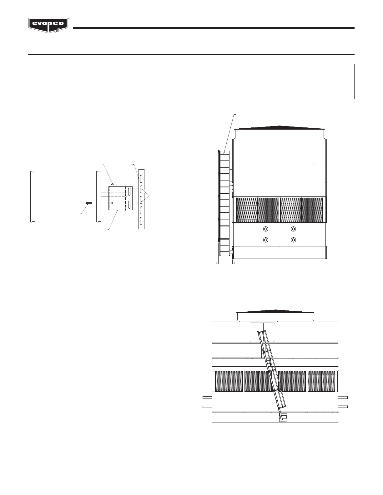
Optional Sloped Ladders
When sloped ladders are supplied with a unit, they are shipped
in the basin section, if there is room. One sloped ladder will be
provided for each cell. Assembly is identical for each cell.
Sloped ladders are attached at a minimum of three points.
Taller units will have four attachment points. At each point of
attachment, the ladder will be fitted with a ladder bracket
assembly. The ladder bracket assembly looks like a metal box
and is shown in detail (component #4) in Figure 21 below. The
upper two assembly brackets are factory mounted to the ladder
and are not adjustable. These two brackets define the slope of
the ladder. The lower brackets are adjustable. See Figures 22
and 23 for drawing of the final ladder assembly.
To install the ladder assembly, follow the steps outlined below
which refer to Figure 21:
1. Remove the ladder bracket mounting bolts (A) from the
ladder mounting channels (B) on pan and casing sections.
2. Loosen, but do not remove, the ladder bracket and
assembly bolts (C).
3. Slide the ladder bracket assembly (D) over the ladder
mounting channel (B) located on the unit panels. o not
remove the ladder bracket assembly (D) from the ladder.
4. Align the bolt holes and reinstall the ladder bracket
mounting bolts (A) through the ladder bracket assembly
and the ladder mounting channels (B).
5. Tighten all bolts.
6. Tighten the adjusting screw (E) in the adjustable mounting
bracket where applicable.
LADDER
MOUNTING
CHANNEL (b)
ADJUSTING SCREW (e)
(WHEN APPLICABLE)
LADDER BRACKET
MOUNTING BOLTS (a)
LADDER BRACKET
ASSEMBLY BOLTS (c)
LADDER BRACKET
ASSEMBLY (d)
Figure 21– etail of Ladder, Ladder Bracket Assembly
and Mounting Channel
NOTE: Upper Section of Unit Must Be Properly Oriented
with Respect to Lower Section. All Mounting Brackets Must
be on Same Side of Unit. Refer to Certified Print For Proper
Orientation.
LADDER SHIPS LOOSE FOR
FIELD MOUNTING (BY OTHERS)
Figure 22 – End View of Ladder Assembly
ACCESS
DOOR
Figure 23 – Side View of Ladder Assembly

13
ESW4 Closed Circuit Coolers
Optional Wor ing Platform and Ladder
The working platform and ladder will either be shipped in the basin or shipped separately due to basin accessories that interfere
with storage. The platform is partially assembled prior to shipment for minimal field assembly.
The platform and ladder assembly should be attached after the unit is fully rigged. Follow the instructions below.
7,7/(
&87
1&
'5$:1
*$ 5$:
3$5712 5(912
$//¡+2/(66+28/'%(¡
86(67$,1/(6667((/1&6(7836+((7
67$,1/(6667((/237,21
3$5712 5(912
5(9,6,216
3$57
1(;7
6,=(
,1)2
%<
$66( %/<
$7/
12 $7/
5$:
127(
(9$3&2,1&
'$7(
&+.'
%<
&21),'(17,$/
7KLVGRFXPHQWLVWKHSURSHUW\RI(YDSFR,QF,WVKRXOGQRW
EHFRSLHGRUGLVFORVHGZLWKRXWSULRUZULWWHQDXWKRUL]DWLRQ
6&$/(
127(6
3/$7)25 *5$7,1*1276+2:1
)25&/$5,7<
$'(7$,/$
%'(7$,/%
'
'(7$,/'
(
'(7$,/(
&
'(7$,/&
6(&85(',$*21$/
683325772'(&.
683325786,1*
*5$'(+$5':$5(
'(&.
6833257
',$*21$/
6833257
6(&85('(&.6833257
72&211(&7,213/$7(6
86,1**5$'(
+$5':$5(
'(&.
6833257
&211(&7,21
3/$7(
6(&85('(&.683325772
&211(&7,213/$7(686,1*
*5$'(+$5':$5(
',$*21$/
6833257
&211(&7,21
3/$7(
6(&85(5$,/,1*),77,1*
72)521772(3/$7(86,1*
*5$'(+$5':$5(
5$,/,1*
),77,1*
)5217
72(3/$7(
/2:(5
&+$11(/
$66<
/$''(5
&+$11(/
6(&85(/$''(5
&+$11(/672/2:(5
&+$11(/$66( %/<
2181,786,1*
*5$'(+$5':$5(
5()
)52 723
2)72(3/$7(
727232))7*
),77,1*621/$''(5 $<
1(('72%($'-867('
,1),(/'
6(1'7+,6'5$:,1*727+(6+,33,1*'(3$570(17
72%(3/$&(',17+(5,**,1*3$&.$*(
),(/'$66<3/$7)25 *(1$55
176
1/1 *$
*$
5(3/$&('6$)(7<
&+$,16:6:,1**$7(
$ *
Y
Figure 23 – Ladder Assembly
14
ESW4 Closed Circuit Coolers
General Information - Start-up & Maintenance Start-up Details
Shipping Choc s and Debris
Remove any chocks that have been placed inside the unit for shipping purposes. Be sure to remove the chocks from between the
fan and fan guard if applicable. Clean all debris from the basin prior to start-up. Clean and secure all access doors.
Pump Discharge Line
Connect the riser pipe from the pump discharge on the basin section to the riser pipe on the coil/fan section using the flexible
connection and hose clamps provided.
Bleed-off Line
A bleed-off line and valve are installed on the unit when shipped with a pump. On units shipped without a pump (remote sump
applications) make sure a bleed-off line and valve are properly sized and installed on the discharge side of the pump and
connected to a convenient drain. In either case, the bleed-off valve should be fully open.
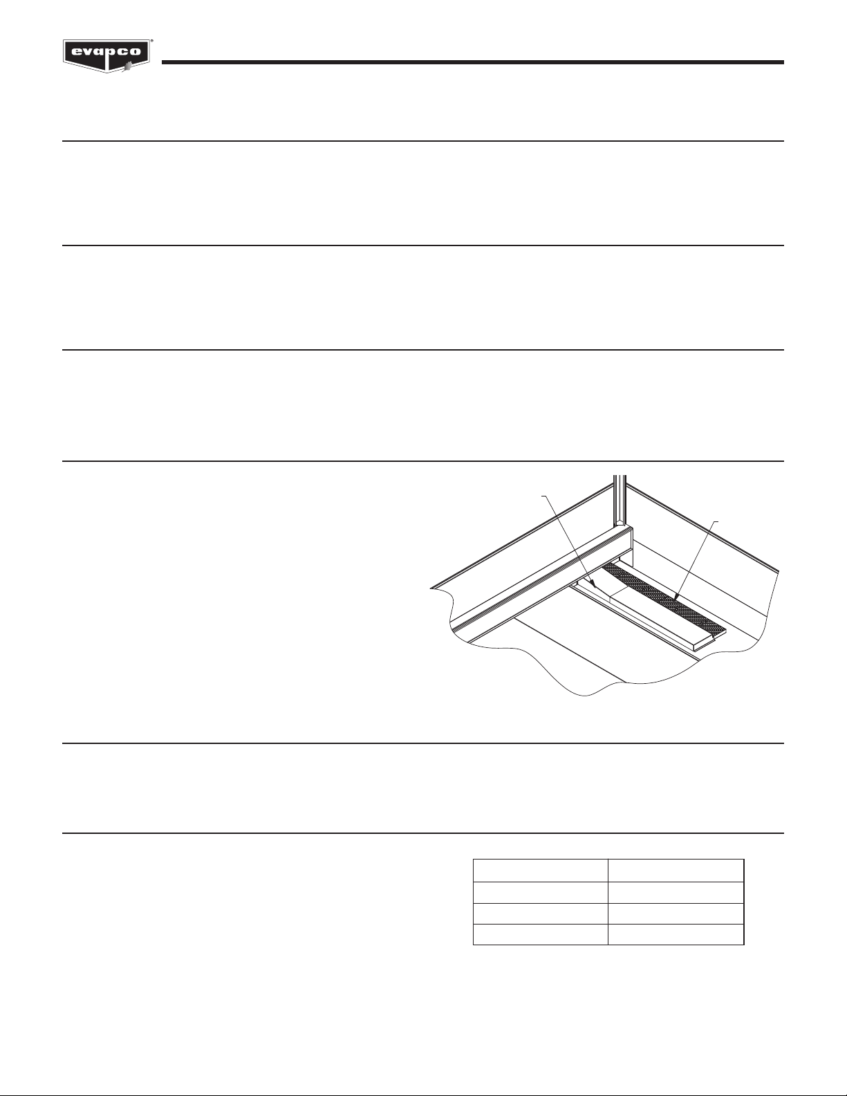
Strainer
Check the strainers, if applicable, in the basin section to make
certain they are in the proper location over the pump suction,
along side of the anti-vortex hood. (See Figure 24.)
Screens
Protective fan screens are provided across the top of the fan cylinders of all models. Check and tighten all bolts.
Float Valve Adjustment
The float valve is pre-set at the factory; however, adjustment
should be checked after rigging. The float valve should be
adjusted so that the centerline of the float is at the
measurement shown in Table 6 from the basin bottom. Raise
or lower the float by using the wing nuts on the vertical
threaded rod only. o not adjust the horizontal rod.
SUCTION HOOD
STRAINER
Figure 24 – Strainer Location
Unit Width Level
8.5’ (2.6m) 9” (23cm)
12’ (3.6m) 10” (30cm)
14’ (4.2m) 9” (23cm)
Table 6 – Recommended Water Level
15
ESW4 Closed Circuit Coolers
Starting Sequence
Before starting the unit, check that all access openings, safety screens and covers are in place. Start the unit as outlined below:
1. Fill the pan to the overflow level.
2. Bump start and check the spray water pump(s) for proper rotation. irectional arrows are found on the pump impeller housing.
3. Bump start and check the fan(s) for proper rotation. irectional arrows are placed on the side of the fan cylinder.
Maintenance
Once the installation is complete and the unit is turned on, it is important that it be properly maintained. Maintenance is not difficult
or time-consuming but must be done regularly to assure full performance of the unit. Refer to the operation maintenance
instructions enclosed with the unit for proper maintenance procedures.
Freeze Protection
Proper freeze protection must be provided if the unit is located in a cold climate. Refer to the operation maintenance instructions as
well as product bulletins for further information.

EVAPCO, Inc. • P.O. Box 1300 • Westminster, M 21158 USA
PHONE: 410-756-2600 • FAX: 410-756-6450 • E-MAIL: [email protected]
©2020 EVAPCO, Inc.
Printed on recycled paper
using soy-based ink
Accessories can ship in a variety of locations depending on the type of accessory, the size of the unit and the other accessories
purchased with the unit. See Table 7 for a guide to accessory location.
Unit Accessories Shipping Location
Aluminum Ladder Shipping Location is Unit and Accessory ependent
- If Space is Available: Strapped Inside Unit Basin
- If No Space is Available: Shipped Separately on Truck Bed
rip Channels for Multi Cell Units Strapped Inside Unit Basin
ischarge Attenuation Mounted Loosely Bolted on Basin Section
Shipping Location is Unit ependent
Electric Basin Heater - End Mounted Heater: Installed in Unit Basin
- Side Mounted Heater: Strapped Inside Basin Section
Shipping Location is ependent on Control Panel Size
Electric Basin Heater Control Panel - If Space is Available: Mounted on Unit Basin
- If No Space is Available: Boxed, Wrapped and Wire Tied Inside Basin Section
Electric Basin Heater Low Water Cutout Shipped in Rigging Box
Shipping Location is Unit ependent
Electric Basin Heater Thermostat - End Mounted Thermostat: Mounted on Basin Section
- Side Mounted Thermostat: Shipped in Rigging Box
Electronic Water Level Control Probes Mounted in PVC standpipe
Electronic Water Level Control PVC Standpipe Strapped Inside Unit Basin
Shipping Location is Unit and Accessory ependent
External Service Platform with Ladder - If Space is Available: Strapped Inside Basin Section
- If No Space is Available: Crated and Shipped Separately on Truck Bed
Factory Mounted Crossover Piping Welded to Coil Connections
Fan Motor Shipped Loose on 8.5’ (2.6m) Wide Units
Shipping Location is Unit and Accessory ependent
Fan Screens (If not mounted) - If Space is Available: Strapped Inside Basin Sections
- If No Space is Available: Crated and Shipped Separately on Truck Bed
Shipping Location is Unit and Accessory ependent
Fan Screen Supports (If not mounted) - If Space is Available: Strapped Inside Basin Section
- If No Space is Available: Crated and Shipped Separately on Truck Bed
Hot Water or Steam Coil Installed in Unit Basin
Low Water Cutoff for Pump Shipped in Rigging Box
Shipping Location is Unit and Accessory ependent
Motor avit and Base - If Space is Available: Strapped Inside Basin Section
- If No Space is Available: Crated and Shipped Separately on Truck Bed
Remote Sump Trash Screen Installed In Unit Basin
Rigging Hardware Shipped in Rigging Box
Safety Cage Attached to the Ladder
Sealer Tape Shipped in Rigging Box
Sump Sweeper Piping with and without
High Flow Eductors Installed in Unit Basin
Vibration Switch Mounted in Fan Section
Water Level Indicator Strapped Inside Unit Basin
Table 7 – Unit Accessory Shipping Location
Other EVAPCO Accessories manuals


