EVAPCO EAFWD Manual
for
LIFE
Operation and
Maintenance Instructions
For EVAPCO Air Cooled, Adiabatic and Spray
Fluid Coolers and Condensers
International Institute of
Ammonia Refrigeration
www.iiar.org
Member of

2
for
LIFE
Operation and Maintenance Instructions
Table of Contents
3 Introduction
3 Safety Precautions
4 Terminology
4 Receiving
4 Structural Steel Support
5 Rigging
5 Horizontally Mounted Flat Products (EAFWD/EAFCD)
6 Forkli Li
6 Crane Li
8 Required Liing Requirements – Flat EC Fan Models
9 Required Liing Requirements – Flat NEMA
Fan Models
10 V-Bank Style Products (EAVWD/EAVCD,
EAVWA/EAVCD and EAVWS/EAVCS)
10 Forkli Li
11 Crane Li
12 Required Liing Requirements – V Coil EC
Fan Models
13 Required Liing Requirements – V Coil NEMA
Fan Models
13 Initial Storage and/or Idle Period Recommendations
14 International Building Code Provisions
14 Initial and Seasonal Start-Up and Shut-Down
14 General
14 Initial and Seasonal Start-Up
15 Seasonal Shutdown
15 Dry, Adiabatic or Spray Fluid Coolers
15 Air Cooled, Adiabatic or Spray Condensers
15 Basic eco-Air Series Sequence of Operation
16 Maintenance Instructions
16 Cleaning Hydraulically
17 Cleaning with Compressed Air
17 Cleaning with Brushes
17 Cleaning the Fans
17 Adiabatic Pre-Cooling System – If Equipped
18 Operation (Adiabatic Pre-Cooling System)
18 Maintenance (Adiabatic Pre-Cooling System)
19 Spray System – If Equipped
19 Operation
19 Maintenance (Spray System)
20 Inlet Water (Adiabatic & Spray Systems)
20 Water Quality Guidelines (Adiabatic Pad Systems &
Adiabatic Spray Systems)
21 Maintenance Checklist
22 Fan System
22 Cold Weather Operation
22 Unit Layout
22 Freeze Protection
23 Troubleshooting
23 Replacement Parts
24 Replacement Part Drawings
24 eco-Air Flat NEMA Fans
24 eco-Air Flat EC Fans
25 eco-Air VCoil NEMA Fans
25 eco-Air VCoil EC Fans
26 eco-Air Adiabatic System Components
26 eco-Air Spray System Components
27 Notes

3
Introduction
Congratulations on the purchase of your EVAPCO air cooled unit. EVAPCO equipment is constructed of the highest quality materials and
designed to provide years of reliable service when properly maintained.
Thoroughly clean road salt, dirt and debris from unit immediately aer delivery. Residue le on product surfaces can cause damage that is
not covered by any warranty. All new cooling equipment and associated piping should be pre-cleaned and flushed to remove grease, oil,
dirt, debris and other suspended solids prior to operation. Any pre-cleaning chemistry should be compatible with the cooling equipment’s
materials of construction. Alkaline formulations should be avoided for systems which include galvanized materials of construction.
Closed hydronic systems connected to a dry fluid cooler should be pre-cleaned and flushed to remove debris, grease, flash rust, oil, and
other suspended solids prior to operation. EVAPCO recommends the use of inhibitor chemistry or inhibited glycol to minimize corrosion
and scale during normal operation.
Air cooled equipment is oen remotely located and periodic maintenance checks are oen overlooked. It is important to establish a
regular maintenance program and be sure that the program is followed. This bulletin should be used as a guide to establish a program. A
clean and properly serviced unit will provide a long service life and operate at peak efficiency.
This bulletin includes recommended maintenance and maintenance intervals for unit start up, unit operation and unit shutdown. Please
note: the maintenance intervals are minimums. Maintenance should be performed more oen when operating conditions necessitate.
Become familiar with your air cooled equipment. Refer to the isometric drawings located on pages 21-23 for information on the arrange-
ment of components in your equipment.
If you should require any additional information about the installation, operation or maintenance of this equipment, contact your local
EVAPCO representative. You may also visit www.evapco.com or www.mrgoodtower.com for more information.
Safety Precautions
Qualified personnel should use proper care, procedures and tools when operating, maintaining or repairing this equipment in order to
prevent personal injury and/or property damage. The warnings listed below are to be used as guidelines only.
Never operate this equipment without fan screens and access panels properly secured and in place.
Each coil in this unit ships from the factory with a nitrogen charge on the coils. Verify that the nitrogen charge is
still applied before installing unit. Release pressure in each coil before installing heat transfer fluid piping.
An optional factory provided disconnect switch may be located on the unit for each fan motor associated with this
equipment. Before performing any type of service or inspection of the unit make certain that all power has been
disconnected and locked in the “OFF” position.
The top horizontal surface of any unit is not intended to be used as a working platform. No routine service work is
required from this area.
Closed hydronic systems connected to either a closed-circuit cooler or dry cooler should be pre-cleaned and
flushed to remove debris, grease, flash rust, oil, and other suspended solids prior to operation. EVAPCO recom-
mends the use of inhibitor chemistry or inhibited glycol to minimize corrosion and scale during normal operation
EVAPCO requires that all external piping and fittings be externally supported, the supplied connections are not
designed to support external piping or fitting weights. Additional weight to the connections or coil in any way
could cause damage to the unit not covered under warranty.

4
Terminology
Throughout this manual, the terms “Flat” and “V Coil” are used. Below is a list of EVAPCO eco-Air Dry Fluid Cooler and Air Cooled
Condenser product offerings and associated terminology.
eco-Air Series equipment includes the following product models:
<Flat Air Cooled
• EAFWD - Dry Fluid Cooler
• EAFCD - Air Cooled Condenser
<V Coil Air Cooled
• EAVWD - Dry Fluid Cooler
• EAVCD - Air Cooled Condenser
Receiving
Carefully inspect all units upon arrival to assure that no damage has occurred during shipment. This includes searching for dirt and debris
caused by shipping, as well as inspecting all components and accessories for physical damage. If any units have been damaged during
transit, immediately notify the carrier and file a claim with that carrier.
The coils on all EVAPCO eco-Air series coolers and condensers are shipped from the factory with a low-pressure nitrogen charge.
Maintain the nitrogen charge until connecting the unit to the system piping.
To confirm this nitrogen charge, quickly open then close the valve located on the coil header and listen or feel for escaping nitrogen. A
coil without the factory nitrogen charge may be an indication of damage during shipment. In this case, the coil should be pressure tested
with dry nitrogen gas to assure that it is leak free prior to installation. Please notify your EVAPCO representative before installing any unit
that has lost the factory nitrogen charge during shipment.
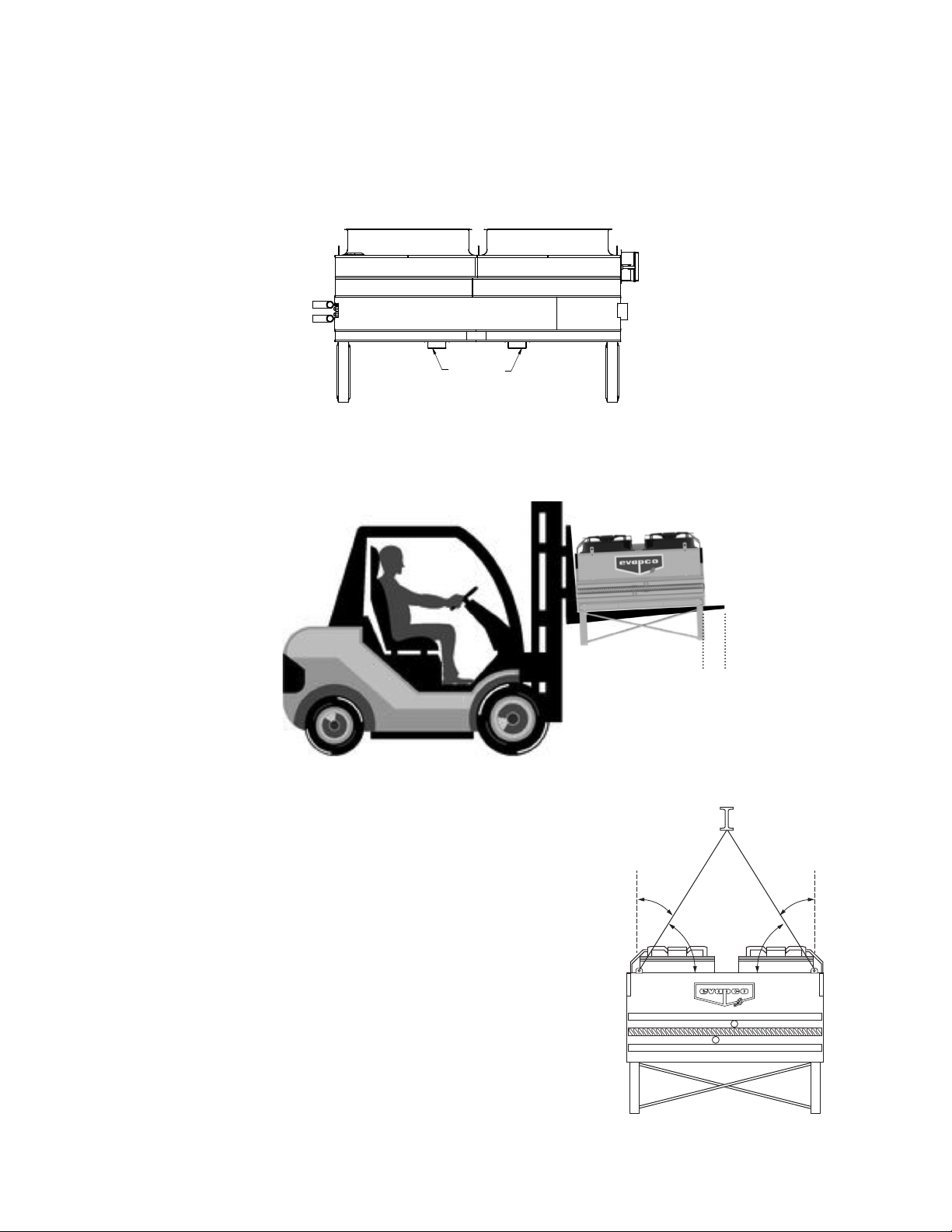
Structural Steel Support
Two structural “I” beams running the length of the unit are required for supporting the eco-Air series units. These beams should be
located underneath the outer flanges of the unit as shown in Figure 1. See Table 1 for Steel Support Dimensions.
Mounting holes, 3/4” in diameter, are provided for bolting the unit to the structural steel. Refer to the recommended structural steel
support drawing and certified print for exact bolt hole location.
Beams should be sized in accordance with accepted structural practices. Maximum deflection of the beam under the unit should be
1/360 of the unit length, not to exceed 1/2”.
The supporting “I” beams should be level before setting the unit in place. Do not level the unit by shimming between it and the beams as
this will not provide proper longitudinal support.
Support beams and anchor bolts are to be provided by others.
<V Coil Adiabatic
• EAVWA - Adiabatic Fluid Cooler
• EAVCA - Adiabatic Air Cooled Condenser
<V Coil Spray
• EAVWS - Spray Fluid Cooler
• EAVCS - Spray Air Cooled Condenser

5
Rigging
All eco-Air Series air cooled units covered in this manual are designed to be removed from the truck via crane. Smaller units that are less
than 27 feet in length also have provisions for removal from the truck via forkli. These units can be installed onto the structural steel in the
same manner as removed from the truck.
Ensure that the crane operator and/or the truck driver li the unit securely. Always consider the weight of the unit with regard to crane or
forkli.
Tubes, return bends, coil connections and headers are never to be used for liing.
Remove any packaging material and verify that no damage has occurred. Slightly bent fins can be repaired easily using a fin comb or
needle nose pliers.
Damaged tubes are only to be repaired by a qualified welder. If the damaged tubes cannot be repaired by your welder contact your local
EVAPCO representative to arrange for inspection and/or repairs.
Flat Coil Configuration Products (EAFWD/EAFCD):
Flat coil units are typically shipped with legs attached. However there could be instances when flat coil units are strapped to a wooden
pallet or enclosed in an open slatted or fully enclosed crate. To avoid handling damage, EVAPCO recommends that the product is off-
loaded from the vehicle while still attached to its pallet or in its crate if provided.
When flat units are shipped crated with the legs removed, the legs will need to be attached before placing the unit on the structural steel.
Below is a drawing showing proper attachment of the legs to the unit.
eco-Air Series Supporting Steel Dimensions
V Models Dry & Spray Unit
Base Width (W)
Adiabatic Unit
Base Width (W)
4’ Wide 4’ 2” 5’ 10”
7’ Wide 7’ 2-1/2” 8’ 9-1/2”
8’ Wide 7’ 3-3/4” 9’ 3/4”
F Models Base Width (W) –
6’ Wide 5’ 7-5/16” –
7’ Wide 6’ 11-1/8” –
8’ Wide 7’ 7” –
Length (L)
Base Width (W)
Length (L)
Base Width (W)
Length as shown on “unit length range
(L)” on unit certified drawing
LEG PLENUM
CHANNEL
FLAT
WASHER M12 BOLT
NUT
Figure 1 – Supporting Steel Diagram
Figure 2 – Flat Unit Leg Attachement
Table 1 – Structural Steel Support Dimensions
6
Forkli Li:
Ensure that the forkli truck is large enough to handle the size and weight of the product required to be off-loaded. Unit weights can
be found on the unit certified drawing. Units with a length less than 27 feet are provided with standard EVAPCO steel forkli channels
positioned under the unit. Forkli channels will be identified by a label on the unit. If labels and forkli channels are not present, STOP!,
the unit will need to be rigged via a crane. Forkli channels are only provided on units that are capable of being rigged via forkli. Larger
units will need to be lied via a crane or else unit and coil damage may occur.
Below is a diagram representing the location of the forkli channels on flat units.
The forks must be long enough to protrude at least 12 inches (30 cm) beyond the width of the product.
Under no circumstances, even if forkli channels are fitted, should ‘short forks’ be
used as this will result in damage to the unit casing and/or coil of the unit. Ensure
that the weight is evenly distributed before attempting to li the product. Follow
industry standard forkli recommendations and guidelines.
Crane Li:
Ensure that the crane operator uses adequate straps, chains, spreader bars etc.,
to safely and securely handle the weight of the product. The minimum angles
for liing by crane, when viewed from the unit end, must NEVER be less than a
60°angle from horizontal as shown in Figure 5. When viewed from the side of the
unit the liing angle must always be perpendicular to the unit; any angle could
cause damage to the unit and coil.
To achieve a minimum 60° angle, the chains attached to the liing device must
be a minimum dimension “H” above the unit casing to prevent undue strain on
the liing ears. See Table 2 for the minimum “H” dimension. These liing devices
should not be used for extended lis or where any hazard exists unless safety slings
are employed under the unit.
FORKLIFT
CHANNELS
Figure 3– Flat Coil Forkli Channel Locations
12”
(30 cm)
Figure 4 – Flat Coil Units Forkli Liing Requirements
Figure 5 – Minimum Crane Liing Angles
30°
MAX.
30°
MAX.
60°
MIN.
60°
MIN.

7
Carefully and securely attach chains to unit liing ears based on the below information. Liing ears are provided on the top of the fan
sections for liing the unit into final position. The unit will only be supplied with the liing ears required, THEREFORE USE ALL LIFTING
EARS THAT ARE PROVIDED. The liing ear requirements vary depending on incremental fin length, or distance between tube sheets
and liing ears, therefore you will need to refer to the unit model number to accurately determine which of the below details describes
your unit.
The 6th digit aer the first hyphen in the model number depicts incremental fin length. For example in the model number:
EAVCD-15S2ZKxxxxx-xxxxxxxxxx the Kdepicts the incremental fin length. Possible incremental fin length characters are B, K, and I. This
can be further broken down by the type of fans.
Below is a table for a quick reference guide, showing which unit type applies to which liing ear requirement figure.
H
Figure 6 – Rigging Beam Height Requirements
Unit Width Minimum Height (H)
Dimension (.)
5’ (1.8m) 3.5
7’ (2.2m) 5.0
8’ (2.4m) 5.0
Table 2 – Minimum “H” Dimensions
Table 3 – Liing Ear Requirement Reference
Incremental Fin Length Designator Incremental Fin Length Fan Type Figure Number
B 5’ 9” (1755mm) EC N/A
NEMA 9
K 6’ 4” (1950mm) EC 7
NEMA N/A
I 7’ 8” (2340mm) EC 8
NEMA 10

8
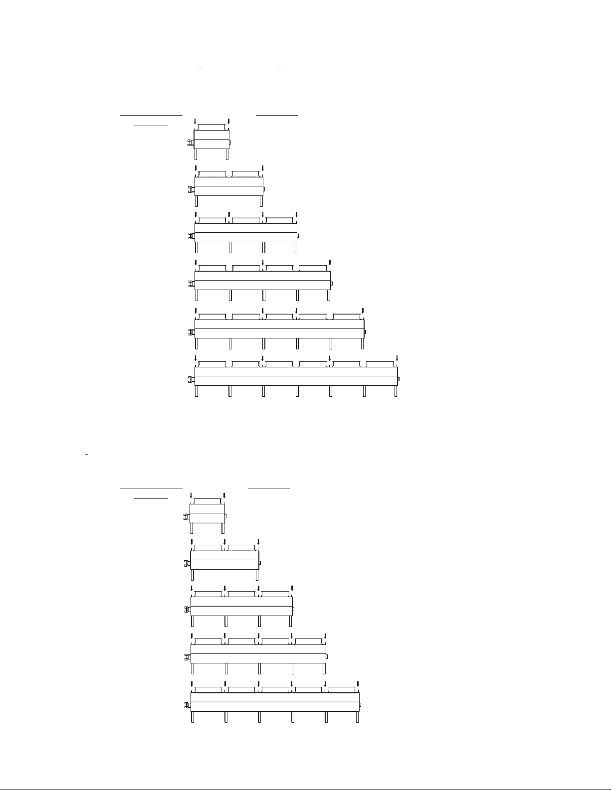
Required Liing Requirements – Flat EC Fan Models
Units with EC Fans will have either a K(6’ 4” [1950mm]), or I(7’ 8” [2340mm]) incremental fin length designator.
Below are the Kunit liing requirements.
The arrows shown on the unit drawings below indicate (2) liing ears per arrow.
Below are I(7’ 8” [2340mm]) incremental fin length units rigging requirements:
The arrows shown on the unit drawings below indicate (2) liing ears per arrow.
Number of fans
in length
1
2
3
4
5
6
Number of fans
in length
1
2
3
4
5
Unit length
Unit length
6’ 8-1/4”
7’ 11-1/2”
13’ 0”
15’ 7-5/8”
19’ 5-3/4”
23’ 3-3/4”
25’ 10-1/2”
30’ 11-7/8”
38’ 8”
32’ 3-1/4”
38’ 8”
Figure 7 – Liing Ear Requirements for 6’ 4” Incremental Fin Length
Figure 8 – Liing Ear Requirements for 7’ 8” Incremental Fin Length
9
Required Liing Requirements – Flat NEMA Fan Models
Units with NEMA Fans will have either a B(5’ 9” [1755mm]) or I(7’ 8” [2340mm]) incremental fin length designator.
Below are the Bunit liing requirements.
The arrows shown on the unit drawings below indicate (2) liing ears per arrow.
Below are I(7’ 8” [2340mm]) incremental fin length units rigging requirements:
The arrows shown on the unit drawings below indicate (2) liing ears per arrow.
Number of fans
in length
1
2
3
4
5
6
Number of fans
in length
1
2
3
4
5
Unit length
Unit length
6’ 1/2”
7’ 11-1/2”
11 9-5/8”
15’ 7-5/8”
17’ 6-3/4”
23’ 3-3/4”
23’ 3-3/4”
30’ 11-7/8”
38’ 8”
29’ 7/8”
34’ 9”
Figure 9 – Liing Ear Requirements for 6’ 4” Incremental Fin Length
Figure 10 – Liing Ear Requirements for 7’ 8” Incremental Fin Length

10
V Coil Configuration Products (EAVWD/EAVCD, EAVWA/EAVCD and EAVWS/EAVCS)
EVAPCO eco-Air V Coil units utilize a skidless design allowing for ease of installation and transportation.
Forkli Li:
Ensure that the forkli truck is large enough to handle the size and weight of the product required to be off-loaded. Unit Weights can be
found on the unit certifed drawing.
Units with a length less than 27 feet are provided with standard EVAPCO steel forkli channels positioned under the unit. Forkli channels
will be identified by a label on the unit. If labels and forkli channels are not present, STOP!, the unit will need to be rigged via a crane.
Forkli channels are provided on all units that are capable of being rigged via forkli. Larger units will need to be lied via a crane or unit
and coil damage may occur.
Below is a diagram representing the location of the forkli channels on V Coil units.
The forks must be long enough to protrude at least 12 inches (30 cm) beyond the width of the product.
Under no circumstances, even using forkli channels, should ‘short forks’ be used as this will result in damage to either the unit casing or
coil of the unit.
Ensure that the weight is evenly distributed before attempting to li the product. Follow industry standard forkli recommendations and
guidelines.
FORKLIFT
CHANNELS
Figure 11 – V Coil Forkli Channel Locations
Figure 12 – V Coil Unit Forkli Liing Requirements
12”
(30 cm)

11
Crane Li:
Ensure that the crane operator uses adequate liing straps, chains, spreader bars etc.,
to safely and securely handle the weight of the product. The minimum angles for liing
by crane when viewed from the unit end, must NEVER be less than a 60° angle from
horizontal as shown in Fig 13. When viewed from the side of the unit the liing angle must
always be perpendicular to the unit; any angle could cause damage to the unit and coil.
To achieve a minimum 60° angle, the chains attached to the liing device must be a
minimum dimension “H” above the unit casing to prevent undue strain on the liing ears.
See Table 4 for the minimum “H” dimension. These liing devices should not be used for
extended lis or where any hazard exists unless safety slings are employed under the unit.
Carefully and securely attach chains to unit liing ears based on the below information. Liing ears are provided on the top of the fan
sections for liing the unit into final position. Unit will only be supplied with the liing ears required, THEREFORE USE ALL LIFTING
EARS THAT ARE PROVIDED. The liing ear requirements vary depending on incremental fin length, or distance between tube sheets
and liing ears, therefore you will need to refer to the unit model number to accurately determine which of the below details describes
your unit.
The 6th digit aer the first hyphen in the model number depicts incremental fin length. For example in the model number:
EAVCD-15S2ZKxxxxx-xxxxxxxxxx the Kdepicts the incremental fin length. Possible incremental fin length characters are A, J, B, K, and
I. This can be further broken down by the type of fans.
Below is a table for a quick reference guide, showing which unit type applies to which liing ear requirement figure.
30°
MAX.
30°
MAX.
60°
MIN.
Figure 14 – Rigging Beam Height Requirements
Table 4 – Minimum “H” Dimensions
Table 5 – Liing Ear Requirement Reference
H
Unit Width Minimum Height (H)
Dimension (.)
4’ (1.2m) 2.5
7’ (2.2m) 5.0
8’ (2.4m) 5.0
Incremental Fin Length Designator Incremental Fin Length Fan Type Figure Number
A 3’ 10” (1170mm) EC 15
J 4’ 3” (1300mm) EC 15
B 5’ 9” (1755mm) NEMA 16
K 6’ 4” (1950mm) NEMA 16
I 7’ 8” (2340mm) NEMA 17
Figure 13 – Minimum Crane
Liing Requirements

12
Required Liing Requirements – V Coil EC Fan Models
Units with EC fan assemblies will have either an A(3’ 10” [1170mm]) or J(4’ 3” [1300mm]) incremental fin length designator.
Below are the liing requirements for these units.
The arrows shown on the unit drawings below indicate (2) liing ears per arrow.
Number of fans
in length
1
2
3
4
5
6
7
8
9
10
Unit length
4’ 10-3/8”
5’ 3-3/8”
8’ 8-3/8”
9’ 6-5/8”
12’ 6-1/2”
13’ 9-3/4”
16’ 4-1/2”
18’ 0”
20’ 2-5/8”
22’ 4-1/8”
24’ 5/8”
26’ 7-3/8”
27’ 10-3/4”
30’ 10-1/2”
31’ 8-3/4”
35’ 1-3/4”
35’ 6-7/8”
39’ 4-7/8”
39’ 4-7/8”
Figure 15 – Liing Ear Requirement for 3’ 10” and 4’ 3” Incremental Fin Lengths

13
Required Liing Requirements – V Coil NEMA Fan Models
Units with NEMA Fans will have either a B(5’ 9” [1755mm]), K(6’ 4” [1950mm]), or I(7’ 8” [2340mm]) incremental fin length designator.
The arrows shown on the unit drawings below indicate (2) liing ears per arrow.
Number
of fans
in length
1
2
3
4
5
6
Number
of fans
in length
1
2
3
4
5
Unit length Unit length
6’ 9-3/8”
7’ 5” 8’ 8-3/8”
12’ 6-1/2”
13’ 9-7/8” 16’ 4-1/2”
18’ 3-1/2”
20’ 2-5/8” 24’ 5/8”
24’ 5/8”
26’ 7-3/8”
31’ 8-3/4”
29’ 9-3/4”
33’ 1/8”
39’ 4-7/8”
35’ 6-7/8”
39’ 4-7/8”
Below are the Band Kunit liing requirements. Below are Iunit liing requirements.
Figure 16 – Liing Ear Requirement for 5’ 9”
and 6’ 4” Incremental Fin Lengths Figure 17 – Liing Ear Requirement
for 7’ 8” Incremental Fin Lengths
Initial Storage and/or Idle Period Recommendations
If the unit will remain inactive for an extended period of time prior to installation it is recommended that the following be performed in
addition to all component manufacturers recommended maintenance instructions.
• The fans must be turned by hand at least once every three months. This can be accomplished by tagging and locking out the unit’s
disconnect, grasping the fan assembly and rotating it several turns.
• If unit remains inactive longer than one month, insulation test motor windings semi-annually.
• See motor manufacturer maintenance and long term storage instructions for more detailed instructions.
• Thoroughly clean road salt, dirt and debris from unit immediately aer delivery. Residue le on product surfaces can cause
damage that is not covered by any warranty.

14
International Building Code Provisions
The International Building Code (IBC) is a comprehensive set of regulations addressing the structural design and installation requirements
for building systems – including HVAC and industrial refrigeration equipment. The code provisions require that the cooling equipment
and all other components permanently installed on a structure must meet the same seismic design criteria as the building.
All items attached to EVAPCO eco-Air Series coolers and condensers must be independently reviewed and isolated to meet applicable
wind and seismic loads. This includes piping, ductwork, conduit, and electrical connections. These items must be attached to the
EVAPCO unit so as not to transmit additional loads to the equipment as a result of seismic or wind forces. EVAPCO requires that all
external piping and fittings be externally supported, the supplied connections are not designed to support external piping or fitting loads.
Additional forces to the connections or coil in any way could cause damage to the unit not covered under warranty.
Initial and Seasonal Start-Up and Shut-Down
General
1. Verify that the overall installation reflects the requirements of the installation guidelines found in EVAPCO Bulletin #320. –
Equipment Layout Manual available at www.evapco.com.
2. Verify all safety interlocks work properly.
3. Examine wiring for loose connections or other obvious damage (quarterly).
4. For units supplied with an EVAPCO controls system see the Controls Operating Manual for motor and controls startup. For units
not supplied with controls see motor manufacturer’s and controls manufacturer’s start up recommendations.
5. If the unit is going to remain inactive for an extended period of time, follow all manufacturer’s fan motor for long term storage.
Properly ventilated plastic sheets or tarps can be used to protect a unit during storage. See your local EVAPCO representative for
additional information on unit storage.
BEFORE BEGINNING ANY MAINTENANCE, BE CERTAIN THAT THE POWER IS TURNED OFF AND THE UNIT IS
PROPERLY LOCKED AND TAGGED OUT!
Initial and Seasonal Start-Up
1. Clean and remove any debris, such as leaves and dirt from the coil face, adiabatic pads (if equipped), and fan screens. Flush the
adiabatic pads to remove any sediment or dirt.
2. If equipped, the factory set flow setter devices on the adiabatic system piping may need to be adjusted to maintain equal
distribution of water flow on both sides of the unit.
3. Fins can be brushed clean with a so bristle brush or pressurized water, not aimed at an angle, but directly onto the fins to clean
accumulated deposits. A fin comb or needle nose pliers can be used to straighten any fins that have become bent. Fins that had
been damaged and straightened with a fin comb may not look like new but will function normally if air spaces remain open.
4. Turn the fan(s) by hand to ensure it turns freely without obstructions.
5. Visually inspect the fan blades. Blade clearance should be approximately 1/4” from tip of blade to the fan cowl.
6. For fluid coolers only, fill the heat exchanger coil with the specified heat transfer fluid and purge air from the system before
pressurizing, using factory supplied coil vents.
NOTE: Dry fluid coolers should only be used on sealed, pressurized systems. Continual aeration of the heat transfer fluid in an
open system can cause corrosion inside the tubes of the cooler leading to premature failure.
For fluid coolers or condensers with optional controls, see EVAPCO Controls Operating Manual for proper start up procedure.

15
Aer the unit has been energized, check the following:
1. Verify fans are rotating in proper direction based on arrow sticker affixed to fan housing.
2. Measure voltage and current on all three power leads of fan motors. The current should not exceed the motor nameplate full load
amp rating.
3. Start the EVAPCO Air Pre-Cooling System if equipped. For Adiabatic units, check for proper pad wetting. For spray units, check to
ensure all nozzles are free from debris and have a uniform spray pattern. If the adiabatic or spray system is not operating correctly,
consult the troubleshooting guide in this manual.
Seasonal Shutdown
Steps should be taken to ensure that when the equipment is shut down for prolonged periods, the unit is managed in the correct fashion.
Dry, Adiabatic or Spray Fluid Coolers
1. Ensure the process is shut down and the system temperature has reached safe shut down condition.
2. If unit is equipped with an adiabatic or spray system ensure that all valves are open and system is completely drained.
3. Switch off the fans and power to the unit.
4. Close the isolating valves by others, if equipped.
5. If the cooler will be subjected to sub-zero temperatures and is not filled with a suitable antifreeze, open the air vent and drain
connection(s) and drain the heat transfer fluid. Applying a positive pressure to the air vent connection(s) will help ensure that there is no
heat transfer fluid retention, which could lead to frost damage.
Air Cooled, Adiabatic or Spray Condensers
1. Ensure that the refrigeration load is removed.
2. If unit is equipped with an adiabatic or spray system ensure that all valves are open and system is completely drained.
3. Switch off the fans and power to the product.
Basic eco-Air Series Sequence of Operation
NOTE: For units with an EVAPCO Controls system refer to the EVAPCO Controls Operating Manual for detailed sequence of
operation.
System Off / No Load
The unit’s fans are off. Adiabatic or spray systems should be off, if equipped.
System/Condensing Temperature Rises
The fans turn on. For a variable speed controller, the fans are turned on to minimum speed, all fans maintaining the same speed. If the
system temperature continues to rise, then the fan speed is increased as required, up to full speed.
If temperatures continues to rise and an adiabatic or spray system is equipped then the water solenoid valve should open and completely wet
adiabatic pads, or spray water from nozzles. Fan speeds are increased and decreased as needed aer adiabatic or spray system is initiated.
NOTE: If the adiabatic or spray unit is equipped with the 2-stage operation accessory, 2 solenoid valves are provided, and the
pre-cooling systems are actuated in 2 stages to reduce overall water consumption.
System/Condensing Temperature Stabilizes
Control the leaving fluid temperature (fluid coolers) or condensing temperature (condensers) by modulating the fan speeds with equipped
controls system.
System/Condensing Temperature Drops
Decrease the fan speed, as required. If equipped, shut off adiabatic or spray system and continue to modulate fan speed.
16
System Off / No Load
The system fans turns off. The adiabatic or spray system should not be used as a means of capacity control, and should not be cycled
frequently. Excessive cycling can lead to scale build-up on the pads or coils (in case of spray).
NOTE: MINIMUM CONTROL POINT FOR PROCESS FLUID SHOULD NEVER BE LOWER THAN 6º F ABOVE PROCESS
FLUID FREEZING TEMPERATURE.
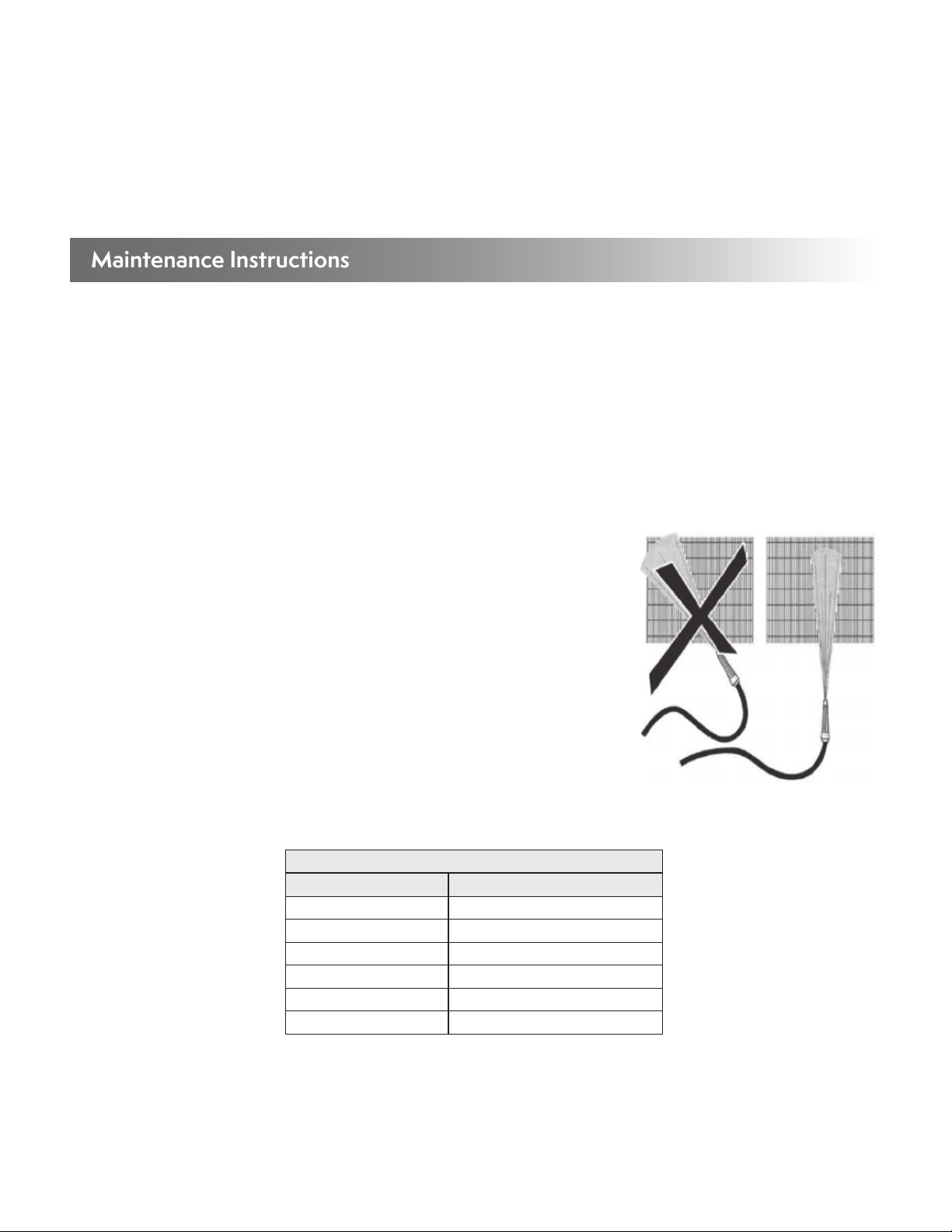
Maintenance Instructions
It is essential to understand that fouled or dirty fins reduce heat transfer.
1. Aer operation for a month, check for fouling of the fins. Inspect with a light between the fins to observe the accumulations of dirt
and dust.
2. Dry dust can normally be removed by compressed air, a so brush, or by a suitable industrial vacuum cleaner. Sweep along the fins
and under no circumstances across the fins.
3. Moist or sticky blemishes or grease should be removed by means of hot water or steam jet cleaning appliances (against the air
direction).
4. Keep the jet of the cleaning appliance at an angle of no more than 15° from vertical position, to avoid bending the fin edges.
Cleaning Hydraulically
When cleaning the coil hydraulically, EVAPCO recommends using water only. If cleaning
products are used ensure that they are compatible with the unit materials of construction.
When cleaning with water under pressure, use a power washing device designed for a
maximum of 600psig or less.
Always clean in the vertical direction. Never across the fins, as this will damage the fins. And
always from the top down to avoid the water spray entering the fans (this can short circuit
the fan motors).
For oily or otherwise difficult to remove dirt, it is possible to add a chemical cleaning agent
to the water used in the power washer. Ensure that the cleaning agent is compatible with the
materials used in the unit and that it is an environmentally friendly agent.
List of recommended cleaning solutions are shown in Table 6 below.
Figure 18 – Always Clean Fins in
Vertical Direction
STAINLESS STEEL/ALUMINUM COILS
Trade Name Manufacturer
CL-122 NALCO
CL-127 NALCO
LMC-44 LW Chemical
SoilSolv DuChem
FS Process Cleaner Zep
Formula 940 Zep
Table 6 – Acceptable Cleaning Solutions

17
Adiabatic Pre-Cooling System – If Equipped
Adiabatic air pre-cooling systems are supplied with many dry fluid coolers and air cooled condensers to enhance the performance of the
unit. The below figure shows the major components of the adiabatic water system.
ADIABATIC
WATER SYSTEM
ADIABATIC
PADS
COIL
SLOPED
DRAIN
CHANNEL
A
B
B
DETAIL A
FLOW SETTER
DEVICE
SOLENOID
VALVE
HAND
VALVE
DISTRIBUTION
PIPE
WATER PRESSURE
REGULATOR
WYE STRAINER
DISTRIBUTION
PADS
DISTRIBUTION
PADS
DETAIL B
DISTRIBUTION
TRAY
DISTRIBUTION
PIPE
Figure 19 – Adiabatic Air Pre-Cooling System Components
Cleaning with Compressed Air
When cleaning with compressed air, use a compressor designed for a maximum of 1,000psig or less. For the purpose of removing dirt
and debris, please ensure that the air stream is COMPLETELY VERTICAL to the fins as the compressed air stream can damage the fins.
Cleaning with Brushes
Dry dust and some dirt can be removed with brushes, possibly in conjunction with compressed air or an industrial vacuum cleaner.
However, ensure that so brushes are used and when possible all cleaning should be from the top down. ALWAYS brush along the fins.
NEVER across the fins, as this will damage the fins.
Cleaning the Fans
ALWAYS ensure that the power to fans has been locked and tagged out prior to cleaning and ensure that the fans cannot be accidentally
started during maintenance.
It is recommended to clean the fans either by means of brushes or with compressed air. When cleaning with compressed air, use a
compressor designed for a maximum discharge air pressure of 125psig or less.

18
Operation (Adiabatic Pre-Cooling System)
All connecting piping to the unit MUST be externally supported. The piping on the unit is not designed to bear additional piping weight.
EVAPCO recommends visually inspecting adiabatic pads and the distribution system regularly during operation and before seasonal
startup. When in operation the pads should be completely wetted (there will be a noticeable color difference). If portions of the pad are
not wetted, inspect the water distribution system for clogs.
Allow the pads to completely dry once every 24 hours with the fans running.
A water pressure regulator (WPR) is located at the end of each unit as shown in Figure 19. The WPR must be set to 50psig using the
provided pressure gauge located between the discharge of the WPR and the inlet of the hand shut off valve.
The water distribution system comes preset from the factory with the correct water flow rate to ensure minimal but even water distribution.
When the adiabatic system is in operation and the flow setters are set correctly a small amount of water will be present in the sloped drain
channel. If it becomes necessary to adjust the water flow rate, adjust the percentage closed of the flow setter devices using a
philips screw driver until only a small amount of water is in the sloped drain channel but ensuring that the adiabatic pads are
completely wetted.
Note that on longer units there are two flow setter devices on each side of the unit and the flow setter percentage closed settings are
different for each. The flow setter device that supplies the longest portion of the unit is designed to be as open as possible.
Maintenance (Adiabatic Pre-Cooling System)
Rinse the adiabatic pads to remove loose sediment or dirt. If further cleaning is required use only a mild and environmentally responsible
cleaning agent that is compatible with the unit and pads materials of construction.
To remove the adiabatic pads use the following instructions. Installation is the reverse of removal.
1. Remove the bolts on the top of the distribution system cover. This allows the distribution cover to be repositioned revealing the
water distribution tray, and the distribution pad.
2. Carefully remove the distribution pad, which is the 2” tall pad positioned between the distribution tray and the large vertical
adiabatic pads.
3. Li the large vertical adiabatic pad to clear the lower support (at the bottom) and remove. It is reccommended to start with the
center pad per module. This will allow for the pads adjacent to the tube sheets to clear metal brackets attached to the tube sheets.
4. Installation is reverse of removal.
Ensure the sloped drain channel and outlet connection are free of debris that would impede water flow by removing the adiabatic pads
and then removing the slotted sloped drain channel cover.
The pad material is a bonded cellulose UV Reistant material. Refer to local codes and ordinances for disposal methods.
Remove and clean the Wye strainer annually to prevent the build up of debris and decreased water flow rate to the adiabatic pads.
19
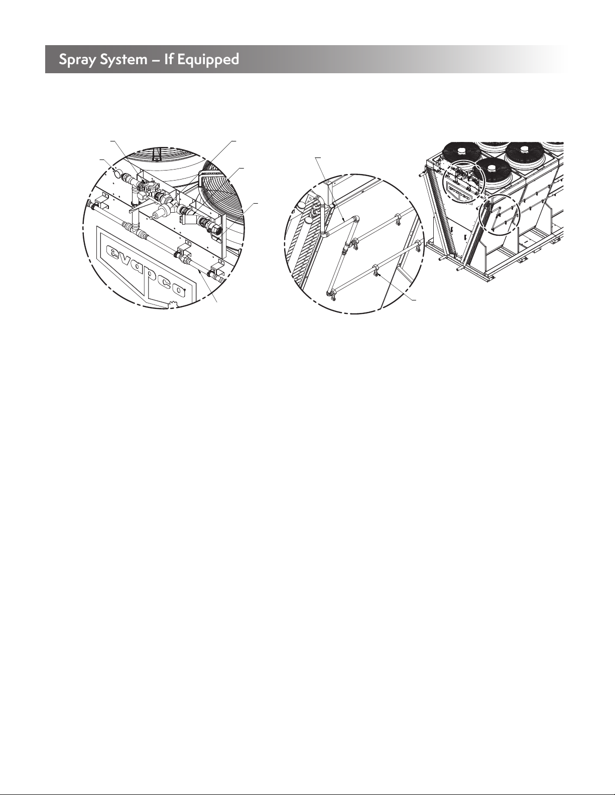
Spray System – If Equipped
Spray systems are supplied with many dry fluid coolers and air-cooled condensers to enhance the performance of the unit. The below
figure shows the major components of the spray system.
A
B
DETAIL A
WYE STRAINER
HAND
VALVE
SOLENOID
VALVE
WATER PRESSURE
REGULATOR
PRESSURE
GAUGE
DISTRIBUTION
PIPE DETAIL B
DISTRIBUTION
PIPE
SPRAY
NOZZLE
Figure 20 – Spray System Components
Operation (Spray System)
All connecting piping to the unit MUST be externally supported. The piping on the unit is not designed to bear additional piping weight.
EVAPCO recommends visually inspecting spray system regularly during operation and before seasonal startup. When in operation the
spray nozzles should be spraying outwards and evenly. If any nozzle isn’t operating correctly, inspect the water distribution system for clogs.
A water pressure regulator (WPR) is located at the end of each unit as shown in Figure 20. For units equipped with spray systems, the
discharge water pressure must be set once the unit is installed in the field. Refer to the technical data sheet in the factory submittal for the
WPR setting required for the submitted design conditions. The provided pressure gauge located at the discharge of the solenoid valve
can be used to validate WPR setting.There are no flow setters on the spray system. Inlet water pressure set correctly on the WPR and a
clean water distribution system will ensure proper operation of the spray system.
NOTE: In addition to the outlined water chemistry guidelines, EVAPCO recommends that dry fluid coolers and air-cooled
condensers equipped with Spray systems limit spray operation to peak ambient and load conditions, about 200 hours a year,
to help limit scale build-up, corrosion and to extend the life of the coil.
Maintenance (Spray System)
Clean the finned coils using the recommendations outlined under “Cleaning Hydraulically.”
Remove the spray nozzles, inspect for debris and clean as necessary.
Remove and clean the Wye strainer annually to prevent the build up of debris and decreased water flow rate to the spray system.
Inlet Water (Adiabatic & Spray Systems)
The water supply temperature and presure are typically around +50°F and +50 psig, respectively for standard city water main lines. The
adiabatic & spray systems require a minimum water pressure of 50 psig at the inlet connection.The adiabatic system piping (see Figures
19 & 20) includes a water pressure regulator to enable the use of high pressure supply water, up to 140 psig, to be connected. The inlet
connection is the highest point on the EVAPCO adiabatic and spray pre-cooling systems, allowing for free drainage of water, aer the
soleniod valve, upon system shutoff. Please refer to the Freeze Protection section of this O&M for more information on protecting the
adiabatic and spray water piping.
Normal municipal and ground water supplies are suitable for use with the adiabatic & spray systems. If other water sources, cleaning
agents, or treatments are to be used, ensure that they are compatible with all of the eco-Air product line materials of construction
including PVC, copper, brass, bonded cellulose, galvanized steel and 304L stainless steel.
20
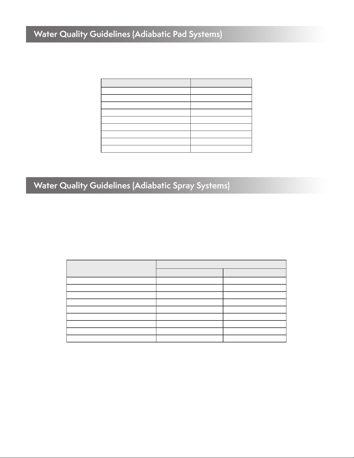
Water Quality Guidelines (Adiabatic Pad Systems)
EVAPCO recommends the below outlined water chemistry guidelines applicable to ADIABATIC PAD air pre-cooling systems for dry
fluid coolers and air-cooled condensers. The water quality guidelines shown below apply to the water which is dripped over the pads.
These guidelines are recommended to extend pad life and limit scale build up on the pads.
Property Adiabatic Spray System
Scenario 1 Scenario 2
pH 6.0 - 8.5 6.0 - 8.5
Conductivity (mhos/cm) <1,500 <1,000
Alkalinity as CaCO3(ppm) <250 <200
Calcium Hardness as CaCO3(ppm) <350 <250
Alkalinity + Calcium <550 <400
Chloride as Cl (ppm) <175 <150
Sulfate (ppm) <225 <200
Chloride + Sulfate <350 <300
Silica as SiO2 (ppm) <150 <150
Property Adiabatic Pads
pH 6.0 - 9.0
Conductivity (mhos/cm) <1,500
Alkalinity as CaCO3(ppm) <250
Calcium Hardness as CaCO3(ppm) <300
Alkalinity + Calcium <500
Chloride as Cl (ppm) <250
Sulfate (ppm) <250
Chloride + Sulfate <400
Silica as SiO2 (ppm) <150
Table 7 – Recommended Water Chemistry Guidelines for Inlet Water to Adiabatic Pad Systems
Table 8 – Recommended Water Chemistry Guidelines for Inlet Water to Adiabatic Spray Systems
Water Quality Guidelines (Adiabatic Spray Systems)
EVAPCO recommends the below outlined water chemistry guidelines applicable to ADIABATIC SPRAY air pre-cooling systems for dry
fluid coolers and air-cooled condensers. The water quality guidelines shown below apply to the water which passes thru the adiabatic
spray system. Although the adiabatic spray nozzles spray water away from the coils, the coils and structure of the unit will get wet when
the spray system is on. Thus, the water quality guidelines shown below are recommended to limit scale build-up and corrosion on the
finned tube bundles.
In addition to the water quality guidelines shown below, EVAPCO recommends designing the system for a maximum of 200 hours of
spray operation per year to help limit the possibility for scale build-up and corrosion.
*Scenario 1 applies when the entering Process Fluid or Superheated Refrigerant temperature is equal to or less than 120F.
*Scenario 2 applies when the entering Process Fluid or Superheated Refrigerant temperature is above 120F.
*For Process Fluid and Superheated Refrigerant temperatures in excess of 212F, please consult with Evapco.
“Process Fluid” or “Superheated Refrigerant” is the fluid that is circulated and cooled inside the coils. The water chemistry guidelines
outlined for Scenario 2 are more stringent than Scenario 1 because entering process fluid or refrigerant temperatures above 120°F can
accelerate the rate of scale formation and corrosion on the finned coil bundles when the Spray System is operational.
If the water chemistry guidelines are not followed or if the spray system is run for prolonged periods of time (>200 hours per
year) or cycled excessively, excessive scale buildup is possible and is not covered under unit warranty.
This manual suits for next models
7
Table of contents
Other EVAPCO Industrial Equipment manuals


