EVAPCO PHC-E Series User manual

PHC-E SERIES
Rigging
Assembly
Instructions
FORCED DRAFT
EVAPORATIVE
CONDENSERS
&

2
PHC PARALLEL HYBRID EVAPORATIVE CONDENSERS
Table of Contents
Method of Shipment ........................................................................ 3
Storage .................................................................................... 3
General ................................................................................... 3
Structural Steel Support ..................................................................... 3
Rigging the Basin Section ................................................................... 4
Extended Lis .............................................................................. 5
Applying Sealer Tape ....................................................................... 6
Rigging Coil / Fan Section ................................................................... 6
Assembly of the Coil / Fan Section to the Basin Section ........................................ 7
Final Assembly & Startup Details ............................................................. 8
Notes .................................................................................... 10
The PHC-E SERIES FORCED DRAFT EVAPORATIVE CONDENSERS
should be rigged and assembled using the instructions and
recommendations outlined in this bulletin.
All personnel should review these procedures, as well as the latest industry-approved installation
practices, prior to rigging and assembly. The information in this bulletin is for informational purposes only.
These instructions do not purport to cover all variations and possible contingencies in connection with
installation. Additionally, the procedures described herein are subject to change without prior notice,
due to EVAPCO, Inc.’s ongoing research and development.
EVAPCO, Inc. makes no representations or warranties with respect to these instructions or the products
described herein. Nor shall EVAPCO, Inc. be responsible for any loss or damage (direct, indirect,
consequential, or other) during installation or handling of equipment aer shipment.
For a full description of EVAPCO’s liability policy, please visit www.evapco.com to access our Terms and Conditions.

3
PHC PARALLEL HYBRID EVAPORATIVE CONDENSERS
Method of Shipment
PHC-E condensers are shipped with the top section(s) separate from the bottom section(s). These sections have mating flanges and
will join together in a waterproof joint when sealed and bolted together as described in the following instructions. Miscellaneous items,
such as sealer, fasteners and any other required materials, are packaged and placed inside the pan for shipment.
Storage
Do not place tarps or other coverings over the top of the units if the units are to be stored before installation. Excessive heat can build
up if the units are covered causing possible damage to the PVC crossflow fill and eliminators. For extended storage, rotate the fan and
fan motor sha(s) monthly. Beyond six months, the fan sha bearings should be purged and regreased prior to startup.
General
For extended lis, or where hazards may exist, it is recommended that safety slings and spreaders be employed for safety.
Refer to the “Extended Lis” section in this bulletin.
NOTE: All casing sections are factory inspected prior to shipment to verify proper fit for rigging. Please take extra care to handle
and rig unit sections per the instructions of this manual to avoid possible distortion and cause poor casing alignment. It is advisable
to check each section upon receipt and during each li to ensure that the factory alignment has not been altered. Should the
field inspection indicate the section alignment (“square”) has been altered, please contact the factory or your local EVAPCO sales
representative for additional instructions to obtain proper section fit.
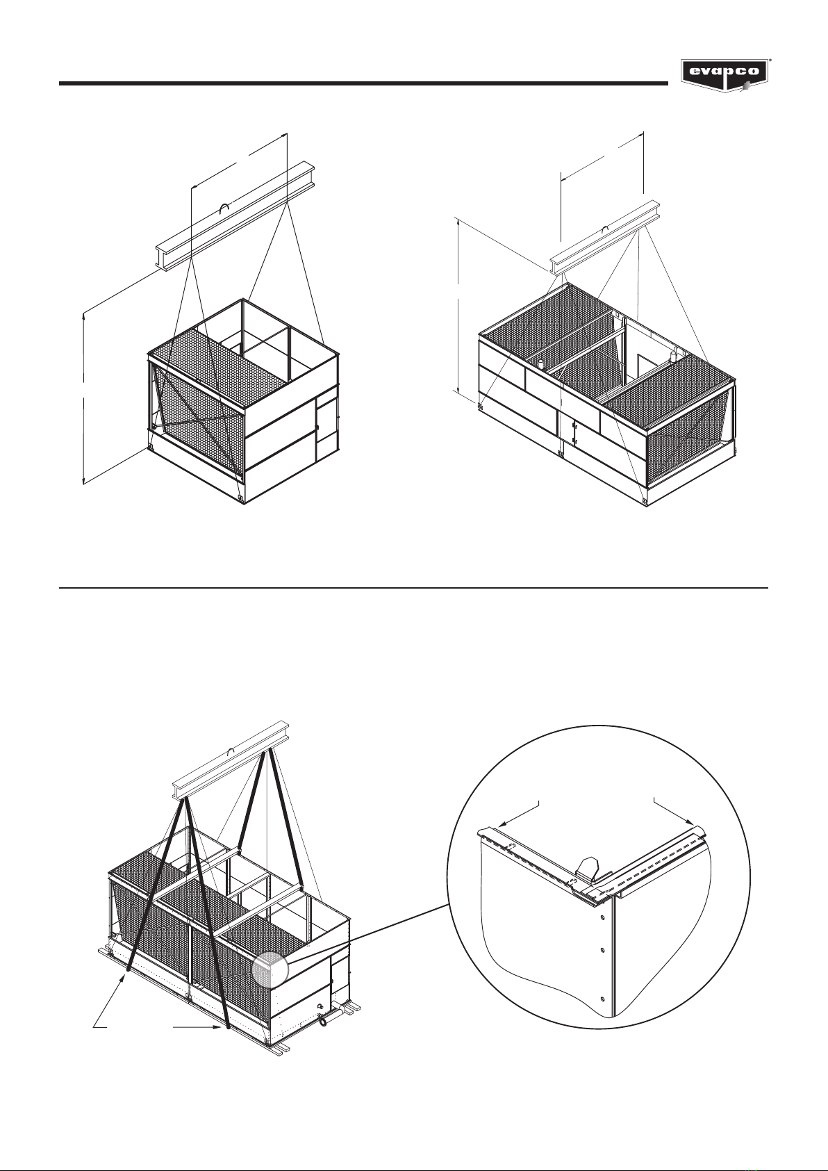
Structural Steel Support
PHC-S-E
Two structural I-beams running the length of the unit are required for supporting the unit. These beams should be located underneath
the outer flanges of the unit. (See Figure 1)
PHC-D-E Models
Three structural I-beams running the width of the unit are required for supporting the unit. Locate two beams underneath the outer
flanges of the unit and locate the third beam laterally along the center of the unit. (See Figure 2)
All Models
Mounting holes, 3/4” (19 mm) in diameter, are located in the bottom flange for bolting to the structural steel. Refer to the
recommended structural steel support drawing and certified print for exact bolt hole location. Bolt the bottom section to the steel
support before rigging the top section.
Beams should be sized in accordance with accepted structural practices and the local building code regulations. Maximum deflection
of the beam under the unit is recommended to be 1/360 of the unit length, not to exceed 1/2” (13 mm). Deflection may be calculated
by using 55% of the operating weight as a uniform load on each beam (see certified print for operating weight).
The supporting I-beams should be level to within 1/8” (3 mm) in 6’ (1.8 m) before setting the unit. Do not level the unit by shimming
between the bottom unit flange and the beams as this will not provide proper longitudinal support.

4
PHC PARALLEL HYBRID EVAPORATIVE CONDENSERS
Rigging Basin Section
Liing devices are located in the lower corners of the basin section for liing and final positioning purposes as shown in Figures 3 and
4. The bottom of spreader beam must be a minimum dimension of “H” above the lowest liing ear to prevent undue strain on the liing
devices. See Table 2 for the minimum “H” dimension. These liing devices should not be used for extended lis or where any hazard
exists unless safety slings are employed under the section. (See “Extended Lis” section for proper arrangement.) Bolt the basin section
to the steel support before rigging the coil / fan section.
PHC-S208 to PHC-S1182 PHC-D621 to PHC-D2050
PHC-L463 to PHC-L842
AIR IN
AIR IN
A
AIR IN AIR IN
AIR IN
AIR IN
C
B
Figure 1 — Recommended Steel Support for S Models Figure 2 — Recommended Steel Support for D Models
PHC-S-E Models PHC-D-E Models
Table 1 — Recommended Steel Support
PHC-E Pan Footprint Dimensions
Box Size A B C
S Models
7x9 86” (2184 mm) - -
7x12 86” (2184 mm) - -
7x18 86” (2184 mm) - -
12x12 142” (3607 mm) - -
12x18 142” (3607 mm) - -
12x24 142” (3607 mm) - -
12x36 142” (3607 mm) - -
D Models
12x24 - 288” (7315 mm) 144” (3658 mm)
14x26 - 312” (7925 mm) 156” (3962 mm)
24x24 - 288” (7315 mm) 144” (3658 mm)
28x26 - 312” (7925 mm) 156” (3962 mm)
Table 2 — Dimensions for Basin Sections
Section Size - Unit Type H W
7 x 9 - S 8’ 10” (2692 mm) 7’ 4” (2235 mm)
7 x 12 - S 11’ 8” (3556 mm) 7’ 4” (2235 mm)
7 x 18 - S 16’ 11” (5156 mm) 7’ 4” (2235 mm)
12 x 12 - S 11’ 8” (3556 mm) 12’ (3.6 m)
12 x 18 - S 16’ 11” (5156 mm) 12’ (3.6 m)
12 x 24 - D 10’4” (3150 mm) 12’ (3.6 m)
14 x 26 - D 11’3” (3429 mm) 14’ (4.2 m)
5
PHC PARALLEL HYBRID EVAPORATIVE CONDENSERS
W
H
W
H
Figure 4 — D Model Basin Section
24’ (7.3 m) and 26’ (7.9 m) Long
Extended Lifts
The recommended method for extended lis is to use safety slings under the unit (see Figure 5). Spreader bars should always be
used between the cables at the top of the section to prevent damage to the upper flanges.
NOTE: The liing points should be used for final positioning only and for liing where no danger exists. If they are used for
extended lis, safety slings and spreader bars should be provided under the sections as shown.
Safety slings, spreaders, and skids should be removed before final positioning of the unit.
SAFETY SLING
Figure 5 — Proper Rigging Method for Extended Lis
SIDE FLANGE
Single Strip Over
Hole Centerline
END FLANGE
Two Sealer Strips
Overlapping
Figure 6 — Proper Sealer Tape Application
Figure 3 — S Model Basin Section
9’ (2.7 m), 12’ (3.6 m) and 18’ (5.5m) Long

6
PHC PARALLEL HYBRID EVAPORATIVE CONDENSERS
Applying Sealer Tape
Once the bottom section has been set on the supporting steel and bolted in place, wipe the top flanges to remove any dirt or moisture.
Place sealer tape over the mounting holes centerline on the side flanges. Apply two strips of sealer tape, one partially overlapping the
other, on the end flanges. The sealer tape should overlap on the corners as shown in Figure 6. Do not splice the sealer tape along the
end flanges and preferably not on the side flanges if it can be avoided. Always remove the paper backing from the sealer tape.
Rigging Coil / Fan Section
Four liing ears are provided in the upper corners of the coil / fan sections for liing. Sections 24’ (7,3 m) or longer will have two
additional liing ears in the middle of the section (See Figures 7 and 8).
CAUTION: USE ALL LIFTING EARS PROVIDED ON THE SECTION. A SPREADER BEAM MUST BE USED FOR
LIFTING THE TOP SECTION(S) AS SHOWN IN FIGURES 7 and 8!
The bottom of the spreader beam must be a minimum dimension
“H” above the lowest liing ear to prevent undue strain on the
liing ears and the section structure. The weight is not evenly
distributed across the width of the coil/fan section. Therefore,
the top connection of the spreader beam will need to be offset
towards the coil side to balance the load. The location of this
connection will vary based on the unit configuration.
See Table 3 for the “H” and “W” dimensions. These liing devices
should not be used for extended lis or where any hazard exists
unless safety slings are employed under the section.
(See “Extended Lis” for proper arrangement)
W
A*
H
Figure 7 — S Model Coil / Fan Section
9’ (2.7 m), 12’ (3.6 m) and 18’ (5.5 m) Long
W
H
Figure 8 — D Model Coil / Fan Section
24’ (7.3 m) and 26’ (7.9 m) Long
Table 3 — Dimensions for Coil / Fan Sections
Section Size - Unit Type H W
7 x 9 - S 8’ 10” (2692 mm) 7’ 4” (2235 mm)
7 x 12 - S 11’ 8” (3556 mm) 7’ 4” (2235 mm)
7 x 18 - S 16’ 11” (5156 mm) 7’ 4” (2235 mm)
12 x 12 - S 11’ 8” (3556 mm) 12’ (3.6 m)
12 x 18 - S 16’ 11” (5156 mm) 12’ (3.6 m)
12 x 24 - D 10’ 4” (3150 mm) 12’ (3.6 m)
14 x 26 - D 11’ 3" (3429 mm) 14’ (4.2 m)

7
PHC PARALLEL HYBRID EVAPORATIVE CONDENSERS
Figure 9 – Mating Upper Coil / Fan Section to Basin Section
Assembly of the Coil / Fan Section to the Basin Section
Before assembling the coil / fan section to the basin section, follow instructions on “Applying Sealer Tape” on page 4 and remove any
loose parts shipped in the pan.
Wipe the flanges on the bottom of the coil / fan section. Check to see that the water distribution connection on the coil / fan section
is in the correct position relative to the basin section (see certified print).
Lower the coil / fan section to within several inches of the basin section making sure the two sections do not touch and the sealer tape
is not disturbed. Place dri pins (see Figure 9) in at least three of the corner mounting holes and gradually lower the coil section into
place using the dri pins to guide the section down accurately onto the mating flange. On long sections, 18’ (5.5 m) and longer, dri
pins should be used midway along the sides as well.
Place fasteners in all four corner bolt holes. Then continue to install the rest of the fasteners working from the corners toward the
center, using dri pins to align the holes. A fastener must be installed in every hole on the side and end flanges.
For units with two coil sections, mount the first as described, and then follow the same procedure for the second section.
NOTE: A rigging box equipped with sealer tape and necessary fasteners is normally
secured inside the pan basin for shipping. Remove the rigging box from the basin
prior to assembly of sections.
8
PHC PARALLEL HYBRID EVAPORATIVE CONDENSERS
Final Assembly & Startup Details
Shipping Materials
Remove any wood chocks, spare parts, or miscellaneous items that have been placed inside the unit for shipping purposes. Clean all
debris from the basin.
Pump Discharge Line
Connect the riser pipe from the pump discharge on the basin section to the riser pipe on the coil / fan section using the flexible
connection and hose clamps provided.
Makeup Water Line
Connect (plumb) the makeup water source to the makeup water connection on the unit. The makeup water supply pressure to the
unit should be maintained between 20 and 50 psig (140 kPa and 340 kPa). Water supply pressure in excess of 50 psig (340 kPa) may
damage the mechanical float valve.
Bleed or Blowdown
EVAPCO recommends an automated conductivity controller to maximize the water efficiency of your system. Based on
recommendations from the selected water treatment company, the conductivity controller should open and close a motorized ball or
solenoid valve to maintain the conductivity of the recirculating water. If the manual valve provided in the bleed-off line on a unit with
factory supplied pump(s) is used to control the rate of bleed, it should be set to maintain the conductivity of the recirculating water
during periods of peak load at the maximum level recommended by the selected water treatment company. If no direction is provided,
the valve should be fully open. On units shipped without a pump (remote sump applications), the bleed-off arrangement and valve
must be provided by the customer.
Float Valve Adjustment
The float valve is preset at the factory however adjustment should be checked aer rigging. The float valve should be adjusted so that
the center of the float is 1” below the center of the overflow connection when the valve is in the fully closed position. Raise or lower the
float by using the wing nuts on the vertical threaded rod. Do not adjust the horizontal rod.
During normal operation, the water level will drop 3” (76 mm) to 4” (102 mm) below the overflow.
Strainer
Check the strainer in the basin to ensure that it is in its proper location over the pump suction.
Screens
Protective screens are provided across the top of the fan cylinders on all models. Inspect the screens to ensure there are no gaps that
may present a safety hazard. Check all screen fasteners to ensure they are tight and secure.
Fan Rotation
Bump start and check the fans for proper rotation. Directional arrows are placed on the inside of the axial fan cylinders.
Pump Rotation
Aer filling the basin to the overflow with fresh water, bump start and check the pump for proper rotation. Directional arrows are found
on the pump impeller housing. Do not start pumps prior to filling the basin with water. Dry pump operation will damage the pump
seals.
Maintenance
Once installation is complete and the unit is turned on, it is important that it be properly maintained. Maintenance is not difficult or
time consuming but must be done regularly to assure maximum trouble free performance of the unit. Refer to the “Operation and
Maintenance Instructions” bulletin enclosed with the unit for proper maintenance procedures.
Also, proper freeze protection must be provided if the unit is located in a cold climate. Refer to the “Operation and Maintenance
Instructions” bulletin supplied as well as factory product bulletins for further information.

9
PHC PARALLEL HYBRID EVAPORATIVE CONDENSERS
Water Treatment and Passivation
Proper water treatment is an essential part of the maintenance required for evaporative cooling equipment. A well designed and
consistently implemented water treatment program will help to ensure efficient system operation while maximizing the equipment’s
service life. A qualified water treatment company should design a site-specific water treatment protocol based on the equipment
(including all metallurgies in the cooling system), location, makeup water quality, and usage.
“White rust” is a premature failure of the protective zinc layer on hot dip or mill galvanized steel which can occur as a result of
improper water treatment control during the startup of new equipment. The initial commissioning and passivation period is critical
for maximizing the service life of galvanized equipment. EVAPCO recommends that site-specific water treatment protocols include a
passivation procedure which details water chemistry, any necessary chemical addition, and visual inspections during the first six (6) to
twelve (12) weeks of operation. During this passivation period, recirculating water pH should be maintained above 7.0 and below 8.0
at all times. Since elevated temperatures have a harmful effect on the passivation process, the new galvanized equipment should be
run without load for as much of the passivation period as is practical.
For more information on water treatment and water chemistry guidelines, refer to the “Operation and Maintenance Instructions”
bulletin supplied.
10
PHC PARALLEL HYBRID EVAPORATIVE CONDENSERS
NOTES:

11
PHC PARALLEL HYBRID EVAPORATIVE CONDENSERS
NOTES:
PHC PARALLEL HYBRID EVAPORATIVE CONDENSERS
CONTACT YOUR
LOCAL EVAPCO
REPRESENTATIVE
OR THE LOCAL
SERVICE CENTER
Visit us at: www.evapco.eu / www.mrgoodtower.eu
TECHNOLOGY FOR THE FUTURE, AVAILABLE TODAY
EVAPCO, Inc. — World Headquarters & Research/Development Center
P.O. Box 1300 • Westminster, MD 21158 USA
EVAPCO, Inc.
World Headquarters
Westminster, MD USA
410.756.2600
Asia Pacific
EVAPCO Asia Pacific Headquarters
Baoshan Industrial Zone
Shanghai, P.R. China
(86) 21.6687.7786
Europe
EVAPCO Europe
EMENA Headquarters
Tongeren, Belgium
(32) 12.39.50.29
EVAPCO East
Taneytown, MD USA
410.756.2600
EVAPCO East
Key Building
Taneytown, MD USA
410.756.2600
EVAPCO Midwest
Greenup, IL USA
217.923.3431
EVAPCO West
Madera, CA USA
559.673.2207
EVAPCO Iowa
Lake View, IA USA
712.657.3223
EVAPCO Iowa
Sales & Engineering
Medford, MN USA
507.446.8005
EVAPCO Newton
Newton, IL USA
618.783.3433
Evapcold Manufacturing
Greenup, IL USA
217.923.3431
EVAPCO Dry Cooling, Inc.
Bridgewater, NJ USA
908.379.2665
EVAPCO Dry Cooling, Inc.
Littleton, CO USA
908.379.2665
Spare Parts: 908.895.3236
EVAPCO Power México S. de R.L. de C.V.
Mexico City, Mexico
(52) 55.8421.9260
Refrigeration Vessels &
Systems Corporation
A wholly owned subsidiary of EVAPCO, Inc.
Bryan, TX USA
979.778.0095
EvapTech, Inc.
A wholly owned subsidiary of EVAPCO, Inc.
Edwardsville, KS USA
913.322.5165
Tower Components, Inc.
A wholly owned subsidiary of EVAPCO, Inc.
Ramseur, NC USA
336.824.2102
EVAPCO Alcoil, Inc.
A wholly owned subsidiary of EVAPCO, Inc.
York, PA USA
717.347.7500
EVAPCO Europe BVBA
Tongeren, Belgium
(32) 12.39.50.29
EVAPCO Europe, S.r.l.
Milan, Italy
(39) 02.939.9041
EVAPCO Europe, S.r.l.
Sondrio, Italy
EVAPCO Europe GmbH
Meerbusch, Germany
(49) 2159.69560
EVAPCO Europe A/S
Aabybro, Denmark
(45) 9824.4999
Evap Egypt Engineering Industries Co.
A licensed manufacturer of EVAPCO, Inc.
Nasr City, Cairo, Egypt
(20) 10 05432198
EVAPCO Middle East DMCC
Dubai, United Arab Emirates
(971) 56.991.6584
EVAPCO S.A. (Pty.) Ltd.
A licensed manufacturer of EVAPCO, Inc.
Isando, South Africa
(27) 11.392.6630
EVAPCO (Shanghai) Refrigeration Equipment Co., Ltd.
Baoshan Industrial Zone, Shanghai, P.R. China
(86) 21.6687.7786
EVAPCO (Beijing) Refrigeration Equipment Co., Ltd.
Huairou District, Beijing, P.R. China
(86) 10.6166.7238
EVAPCO Air Cooling Systems (Jiaxing) Company, Ltd.
Jiaxing, Zhejiang, P.R. China
(86) 573.8311.9379
EVAPCO Australia (Pty.) Ltd.
Riverstone, NSW Australia
(61) 02.9627.3322
EvapTech Asia Pacific Sdn. Bhd
A wholly owned subsidiary of EvapTech, Inc.
Puchong, Selangor, Malaysia
(60) 3.8070.7255
North America
South America
EVAPCO Brasil
Equipamentos Industriais Ltda.
Indaiatuba, São Paulo, Brazil
(55) 11.5681.2000
FanTR Technology Resources
Itu, São Paulo, Brazil
(55) 11.4025.1670
FOR EVAPCO AUTHORIZED
PARTS AND SERVICE,
©2021 EVAPCO Europe
Bulletin PHC-E 129-E_0322
This manual suits for next models
2
Table of contents
Other EVAPCO Industrial Equipment manuals


Popular Industrial Equipment manuals by other brands


Siemens
Siemens SIRIUS 3RW30 Assembly instructions

Schmalz
Schmalz SEAC 10 ECO operating instructions

Brugg Pipesystems
Brugg Pipesystems CASAFLEX installation instructions

PCB Piezotronics
PCB Piezotronics J353B15 Installation and operating manual

Trumpf
Trumpf TC 2020R Student guide

Knorr-Bremse
Knorr-Bremse BENDIX TIM G2 user manual