EVAPCO PMC Series User manual
PMC SERIES
BULLETIN 125D
Rigging
Assembly
Instructions
FORCED DRAFT
EVAPORATIVE
CONDENSERS
&
& eco-PMC
SERIES

PMC & eco-PMC SERIES FORCED DRAFT EVAPORATIVE CONDENSERS
Table of Contents
Method of Shipment ...........................................................................1
Storage .......................................................................................1
General .......................................................................................1
International Building Code Provisions...........................................................1
Structural Steel Support ........................................................................1
Rigging the Basin & Fan (Bottom) Section — Standard Li ........................................ 2
Rigging the Basin & Fan (Bottom) Section — Extended Li ........................................ 3
Applying Sealer Tape ..........................................................................4
Rigging the Heat Transfer Casing (Top) Section...................................................4
Assembly of the Heat Transfer Casing (Top) Section to the Basin & Fan (Bottom) Section.............6
Optional Straight-Sided Hood Section...........................................................7
Rigging Hardware Parts List.....................................................................8
Field Assembly of External Service Platform and Ladder...........................................9
Final Assembly and Startup Details .............................................................10
Maintenance .................................................................................10
Notes........................................................................................11
The PMC & eco-PMC SERIES FORCED DRAFT EVAPORATIVE CONDENSERS
should be rigged and assembled using the instructions and
recommendations outlined in this bulletin.
All personnel should review these procedures, as well as the latest industry-approved installation
practices, prior to rigging and assembly. The information in this bulletin is for informational purposes only.
These instructions do not purport to cover all variations and possible contingencies in connection with
installation. Additionally, the procedures described herein are subject to change without prior notice,
due to EVAPCO, Inc.’s ongoing research and development.
EVAPCO, Inc. makes no representations or warranties with respect to these instructions or the products
described herein. Nor shall EVAPCO, Inc. be responsible for any loss or damage (direct, indirect,
consequential, or other) during installation or handling of equipment aer shipment.
For a full description of EVAPCO’s liability policy, please visit www.evapco.com to access our Terms and Conditions.
PMC & eco-PMC SERIES FORCED DRAFT EVAPORATIVE CONDENSERS
CONTACT YOUR
LOCAL EVAPCO
REPRESENTATIVE
OR THE LOCAL
SERVICE CENTER
Visit EVAPCO’s website: evapco.com
TECHNOLOGY FOR THE FUTURE, AVAILABLE TODAY
EVAPCO, Inc. — World Headquarters & Research/Development Center
P.O. Box 1300 • Westminster, MD 21158 USA
EVAPCO, Inc.
World Headquarters
Westminster, MD USA
410.756.2600
Asia Pacific
EVAPCO Asia Pacific Headquarters
Baoshan Industrial Zone
Shanghai, P.R. China
(86) 21.6687.7786
Europe
EVAPCO Europe BVBA
European Headquarters
Tongeren, Belgium
(32) 12.39.50.29
EVAPCO East
Taneytown, MD USA
410.756.2600
EVAPCO East
Key Building
Taneytown, MD USA
410.756.2600
EVAPCO Midwest
Greenup, IL USA
217.923.3431
EVAPCO West
Madera, CA USA
559.673.2207
EVAPCO Iowa
Lake View, IA USA
712.657.3223
EVAPCO Iowa
Sales & Engineering
Medford, MN USA
507.446.8005
EVAPCO Newton
Newton, IL USA
618.783.3433
Evapcold Manufacturing
Greenup, IL USA
217.923.3431
EVAPCO Dry Cooling, Inc.
Bridgewater, NJ USA
908.379.2665
EVAPCO Dry Cooling, Inc.
Littleton, CO USA
908.379.2665
Spare Parts: 908.895.3236
EVAPCO Power México S. de R.L. de C.V.
Mexico City, Mexico
(52) 55.8421.9260
Refrigeration Vessels &
Systems Corporation
A wholly owned subsidiary of EVAPCO, Inc.
Bryan, TX USA
979.778.0095
EvapTech, Inc.
A wholly owned subsidiary of EVAPCO, Inc.
Edwardsville, KS USA
913.322.5165
Tower Components, Inc.
A wholly owned subsidiary of EVAPCO, Inc.
Ramseur, NC USA
336.824.2102
EVAPCO Alcoil, Inc.
A wholly owned subsidiary of EVAPCO, Inc.
York, PA USA
717.347.7500
EVAPCO Europe, S.r.l.
Milan, Italy
(39) 02.939.9041
EVAPCO Europe, S.r.l.
Sondrio, Italy
EVAPCO Europe GmbH
Meerbusch, Germany
(49) 2159.69560
EVAPCO Air Solutions
A wholly owned subsidiary of EVAPCO, Inc.
Aabybro, Denmark
(45) 9824.4999
EVAPCO Air Solutions GmbH
Garbsen, Germany
(49) 5137.938750
Evap Egypt Engineering Industries Co.
A licensed manufacturer of EVAPCO, Inc.
Nasr City, Cairo, Egypt
(202) 24044997 / (202) 24044998
EVAPCO Middle East DMCC
Dubai, United Arab Emirates
(971) 4.448.7242
EVAPCO S.A. (Pty.) Ltd.
A licensed manufacturer of EVAPCO, Inc.
Isando, South Africa
(27) 11.392.6630
EVAPCO (Shanghai) Refrigeration Equipment Co., Ltd.
Baoshan Industrial Zone, Shanghai, P.R. China
(86) 21.6687.7786
EVAPCO (Beijing) Refrigeration Equipment Co., Ltd.
Huairou District, Beijing, P.R. China
(86) 10.6166.7238
EVAPCO Air Cooling Systems (Jiaxing) Company, Ltd.
Jiaxing, Zhejiang, P.R. China
(86) 573.8311.9379
EVAPCO Australia (Pty.) Ltd.
Riverstone, NSW Australia
(61) 02.9627.3322
EvapTech Asia Pacific Sdn. Bhd
A wholly owned subsidiary of EvapTech, Inc.
Puchong, Selangor, Malaysia
(60) 3.8070.7255
North America
South America
EVAPCO Brasil
Equipamentos Industriais Ltda.
Indaiatuba, São Paulo, Brazil
(55) 11.5681.2000
FanTR Technology Resources
Indaiatuba, São Paulo, Brazil
(55) 11.4025.1670
FOR EVAPCO AUTHORIZED
PARTS AND SERVICE,

1
PMC & eco-PMC SERIES FORCED DRAFT EVAPORATIVE CONDENSERS
Method of Shipment
Forced dra units are shipped either fully assembled (small units) or with the heat transfer casing (top) section(s) separate from the basin
and fan (bottom) section(s). These sections have mating flanges and will join together in a waterproof joint when sealed and bolted
together as described in the following instructions. Miscellaneous items, such as sealer, self-tapping screws and any other required
materials, are packaged and placed inside the pan for shipment.
NOTE: All casing sections are factory inspected prior to shipment to verify proper fit for rigging. Please take extra care to handle
and rig each section per the instructions of this manual to avoid possible distortion and poor casing alignment. It is advisable to check
each section upon receipt and during each li to ensure that the factory alignment has not been altered. Should the field inspection
indicate the section alignment (“square”) has been altered, please contact the factory or your local EVAPCO representative for
additional instructions to obtain proper section fit.
Storage
Do not place tarps or other coverings over the top of the units if the units are to be stored before installation. Excessive heat can build up
if the units are covered causing possible damage to the PVC eliminators. For extended storage beyond six months rotate the fan and fan
motor sha(s) monthly. Also, the fan sha bearings should be purged and regreased prior to startup.
General
For extended lis, or where hazards may exist, it is recommended that safety slings and spreaders be employed for safety. Refer to the
extended li information in this bulletin.
International Building Code Provisions
The International Building Code (IBC) is a comprehensive set of regulations addressing the structural design and installation requirements
for building systems– including HVAC and industrial refrigeration equipment. Since June 2008, all 50 states plus Washington, D.C. have
adopted the International Building Code. The code provisions require that evaporative cooling equipment and all other components
permanently installed on a structure must meet the same seismic design criteria as the building. The PMC series and eco-PMC series
coolers and condensers are compliant with the latest IBC codes up to 1g with standard construction and up to 5.12g with additional
structural modifications.
All items attached to the EVAPCO PMC series closed circuit cooler, PMC series evaporative condenser, or eco-PMC series evaporative
condenser must be independently reviewed and isolated to meet applicable wind and seismic loads. This includes piping, ductwork,
conduit, and electrical connections. These items must be flexibly attached to the EVAPCO unit so as not to transmit additional loads to
the equipment as a result of seismic or wind forces.
Structural Steel Support
Two structural I-beams running the length of the unit are required for supporting the unit. These beams should be located underneath the
outer flanges of the unit as shown in Figure 1. See Table 1 for steel support dimensions.
Mounting holes, 3/4” in diameter, are located in the bottom flange for bolting to the structural steel. Refer to the recommended
structural steel support drawing and certified print for exact bolt hole location. Bolt the bottom section to the steel support before rigging
the top section.
Beams should be sized in accordance with accepted structural practices. Maximum deflection of the beam under the unit should be
1/360 of the unit length, not to exceed 1/2”. Deflection may be calculated by using 55% of the operating weight as a uniform load on
each beam (see certified print for operating weight).
The supporting I-beams should be level to within 1/8” in 6’ before setting the unit. Do not level the unit by shimming between the bottom

2
PMC & eco-PMC SERIES FORCED DRAFT EVAPORATIVE CONDENSERS
flange and the beams as this will not provide proper longitudinal support.
NOTE: Consult the latest IBC code for required steel support layout and structural design.
Figure 1 – Structural Steel Support
A
B
Plan View
End Elevation
H
LIFTING
U-BOLTS
H
LIFTING
U-BOLTS
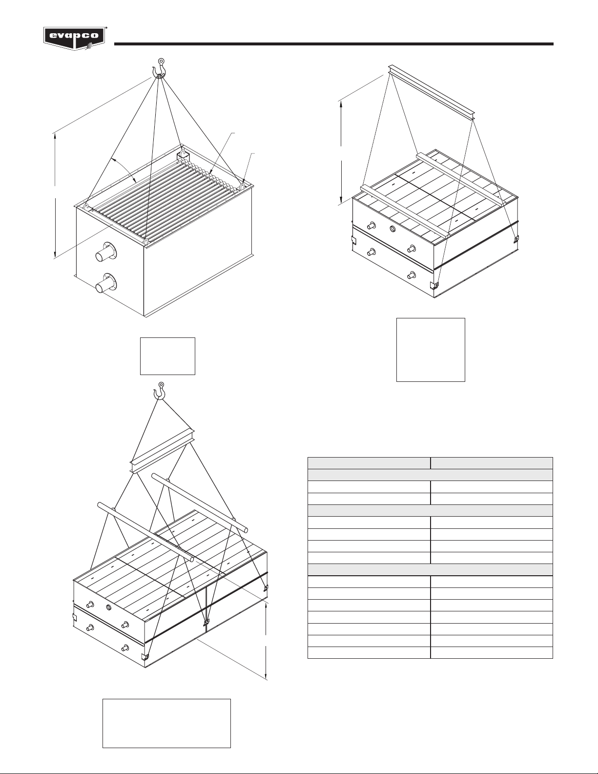
Figure 2 – Basin & Fan Section
(up to 20’ Long)
Figure 3 – Basin & Fan Section
(over 20’ Long)
Rigging the Basin & Fan (Bottom) Section — Standard Li
U-bolts or similar liing points are located in the basin and fan section for liing and final positioning purposes as shown below in Figures
2and 3. Units with lengths up to 20’ have 4 total li points. Units with lengths over 20’ long units have either 6 or 8 li points. See Table
2for the minimum “H” dimensions for rigging the basin and fan assembly. Always use safety slings for extended lis or where any hazard
exits. See the “Extended Lis” section in this bulletin.
NOTE: Use all of the U-bolts or li points provided for liing.
Table 1 – Steel Support Dimensions
(See Table 2 for model numbers corresponding to box size)
PMC-E, eco-PMC
Box Size A B
5’ Wide Models
5’ x 12’ 11’ 11-5/8” 6’ 4”
5’ x 18’ 18’ 1/8” 6’ 4”
10’ Wide Models A B
10’ x 12’ 11’ 11-3/4” 9’ 9-3/4”
10’ x 18’ 18’ 1/8” 9’ 9-3/4”
10’ x 24’ 24’ 7/8” 9’ 9-3/4”
10’ x 36’ 36’ 2” 9’ 9-3/4”
12’ Wide Models A B
12’ x 12’ 11’ 11-3/4” 11’ 10-3/8”
12’ x 18’ 18’ 1/8” 11’10-3/8”
12’ x 20’ 20’ 1/4” 11’ 10-3/8”
12’ x 24’ 24’ 7/8” 11’ 10-3/8”
12’ x 36’ 36’ 2” 11’ 10-3/8”
12’ x 40’ 40’ 2” 11’ 10-3-8”

3
PMC & eco-PMC SERIES FORCED DRAFT EVAPORATIVE CONDENSERS
Rigging the Basin & Fan (Bottom) Section — Extended Li
The recommended method for extended lis is to use slings under the unit as shown in Figure 4. Spreader bars should always be used
between the cables at the top of the section to prevent damage to the upper flanges. See Table 3 for the minimum “H” dimensions for
rigging the basin and fan assembly.
NOTE: The U-bolts or other liing points should be used for final positioning only and for liing where no danger exists. If they are
used for extended lis, safety slings and spreader bars should be provided under the sections as shown.
Safety slings, spreaders, and skids should be removed before final positioning of the unit.
H
SAFETY
SLING
3" X 8"
SPREADERS
SAFETY SLING
Figure 4 – Proper Rigging Method for Extended Lis
Table 2 – Minimum “H” Dimension for the Basin & Fan (Bottom) Section Rigging (Standard Li)
Table 3 – Minimum “H” Dimension for the Basin & Fan (Bottom)
Section Rigging (Extended Li)
(See Table 2 for model numbers corresponding to box size)
* This box size has one 24’ long heat transfer casing top section
** This box size has two 12’ long heat transfer casing top sections
Box Size Model Numbers
PMC-E
Model Numbers
eco-PMC
“H”
Dimension
5’ Wide Models
5’ x 12’ PMC-175E to 240E eco-PMC-183 to 252 12’
5’ x 18’ PMC-250E to 375E eco-PMC-279 to 387 17’
10’ Wide Models
10’ x 12’ PMC-332E to 519E eco-PMC-275 to 559 14’
10’ x 18’ PMC-503E to 778E eco-PMC-479 to 831 18’
10’ x 24’ PMC-772E to 1038E eco-PMC-549 to 1118 23’
10’ x 36’ PMC-1006E to 1556E eco-PMC-959 to 1662 33’
12’ Wide Models
12’ x 12’ PMC-420E to 631E eco-PMC-314 to 688 15’
12’ x 18’ PMC-634E to 939E eco-PMC-632 to 1024 19’
12’ x 20’ PMC-811E to 992E eco-PMC-573 to 1095 20’
12’ x 24’ (1)* PMC-974E to 1258E - 23’
12’ x 24’ (2)** PMC-840E to 1261E eco-PMC-794 to 1376 23’
12’ x 36’ PMC-1269E to 1877E eco-PMC-1263 to 2047 33’
12’ x 40’ PMC-1705E to 1985E eco-PMC-1148 to 2191 36’
Box Size “H” Dimension
5’ Wide Models
5’ x 12’ 12’
5’ x 18’ 17’
10’ Wide Models
10’ x 12’ 14’
10’ x 18’ 18’
10’ x 24’ 23’
10’ x 36’ 33’
12’ Wide Models
12’ x 12’ 15’
12’ x 18’ 19’
12’ x 20’ 20’
12’ x 24’ (1) 23’
12’ x 24’ (2) 23’
12’ x 36’ 33’
12’ x 40’ 36’

4
PMC & eco-PMC SERIES FORCED DRAFT EVAPORATIVE CONDENSERS
Applying Sealer Tape
Once the bottom section has been set on the supporting steel and bolted in place, wipe the top flanges to remove any dirt or moisture.
Place sealer tape over the mounting hole centerline on the side flanges. Apply two strips of sealer tape, one partially overlapping the
other, on the end flanges. (NOTE: Sealer tape is applied completely around the perimeter of the section.)
The sealer tape should overlap on the corners as shown in Figure 5. Do not splice the sealer tape along the end flanges and preferably
not on the side flanges if it can be avoided. Always remove the paper backing from the sealer tape.
For units which have two casing sections, sealer tape must be applied to all internal flanges (Figure 6).
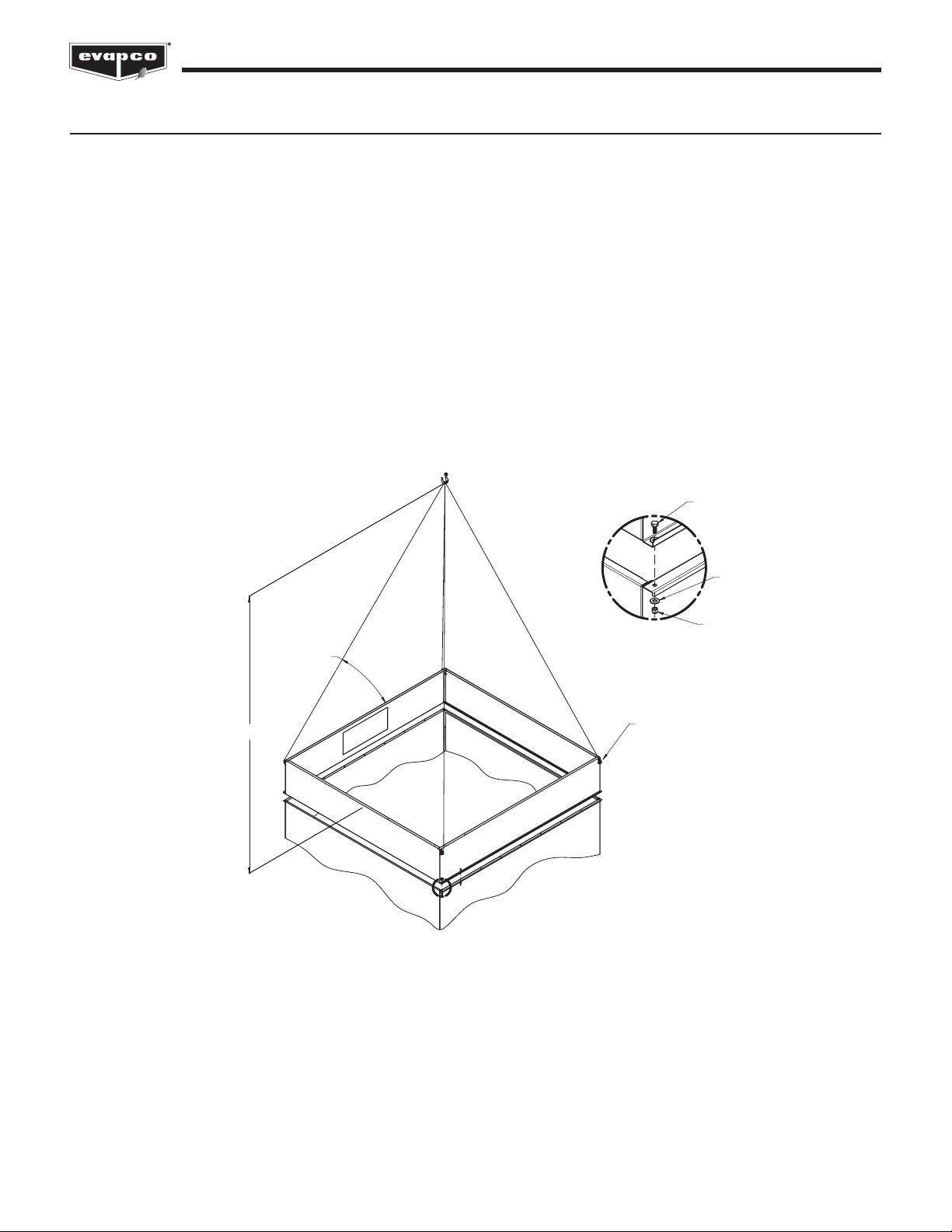
Rigging the Heat Transfer Casing (Top) Section
U-bolts or li points are located inside the casing on the four corners of the coil for small single coil casing sections. These li points are
for liing and final positioning (Figure 7). On larger casing sections, the liing points are on the outside of the casing section (Figures 8
and 9).
The end and center eliminator sections on small, single casing sections should be removed before liing from the U-bolts or li points.
See Table 4 for the minimum “H” dimensions for rigging the casing section. Always use safety slings for extended lis or where any
hazard exits. See the “Extended Lis” section in this bulletin.
NOTE: Use all of the U-bolts or li points provided for liing.
CAUTION: On units shipped as two separate sections, do not assemble sections and attempt to li the entire unit. The
U-bolts and li points are designed to carry only the weight of their individual section.
SIDE
FLANGE END
FLANGE
SEALER
TAPE
SEALER
TAPE
SEALER
TAPE
SEALER
TAPE
SIDE
FLANGE
Figure 5 – Proper Sealer Tape Application Figure 6 – Sealer Detail for Center Joint of
Units with Two or More Casing Sections
5
PMC & eco-PMC SERIES FORCED DRAFT EVAPORATIVE CONDENSERS
LIFTING
U-BOLTS
COIL
ANGLE WITH
HORIZONTAL
MUST
EXCEED
60°
H
H
Figure 8 – Large Casing Section (12’ Long Sections)
BOX SIZES:
10’ x 12’
10’ x 24’
12’ x 12’
12’ x 24’ (2)
H
Figure 9 – Large Casing Section (18’ Long and Up)
BOX SIZES:
10’ x 18’, 10’ x 36’
12’ x 18’, 12’ x 20’
12’ x 24’ (1), 12’ x 36’, 12’ x 40’
Table 4 – Minimum “H” Dimension for Coil Casing Section
Figure 7 – Small, Single Casing Sections
BOX SIZES:
5’ x 12’
5’ x 18’
(See Table 2 for model numbers corresponding to box size)
Box Size “H” Dimension
5’ Wide Models
5’ x 12’ 12’
5’ x 18’ 17’
10’ Wide Models
10’ x 12’ 14’
10’ x 18’ 9’
10’ x 24’ 23’
10’ x 36’ 17’
12’ Wide Models
12’ x 12’ 15’
12’ x 18’ 9’
12’ x 20’ 10’
12’ x 24’ (1) 13’
12’ x 24’ (2) 23’
12’ x 36’ 17’
12’ x 40’ 19’
6
PMC & eco-PMC SERIES FORCED DRAFT EVAPORATIVE CONDENSERS
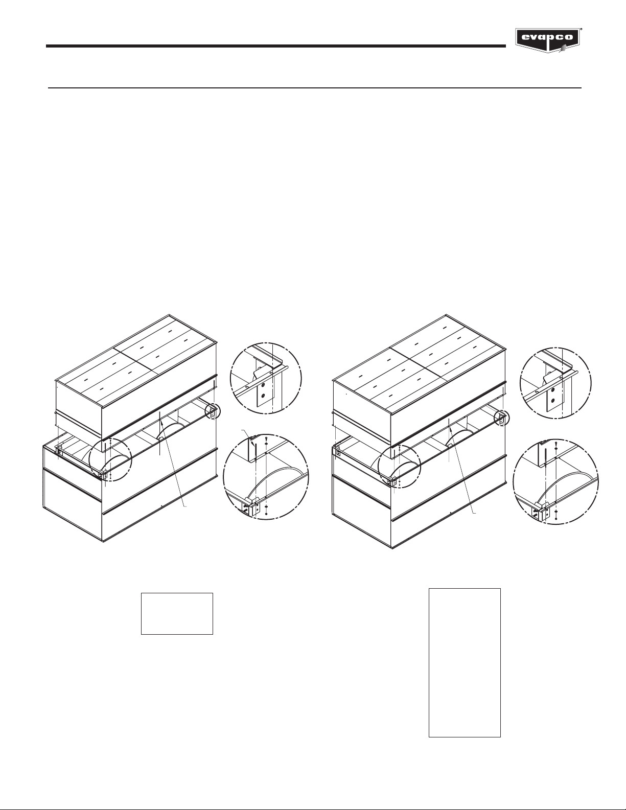
Assembly of the Heat Transfer Casing (Top) Section to the Basin & Fan (Bottom) Section
Before assembling the heat transfer casing (top) section to the cold water basin and fan (bottom) section, remove any loose parts shipped
in the basin.
Wipe the flanges on the bottom of the casing section. Check to see that the water distribution connection on the casing section is in the
correct position relative to the basin and fan section (see certified print). Confirm that sealer tape has been applied to the top of the basin
and fan section as shown in Figures 5 and 6.
Lower the casing section to within several inches of the basin and fan section, making sure the two sections do not touch and the sealer
tape is not disturbed. Place dri pins (see Figure 12 and 13) in at least three (3) of the corner mounting holes and gradually lower the
casing section into place using the dri pins to guide the section down accurately onto the mating flange. On long sections, 18 feet and
longer, dri pins should be used midway along the sides as well.
Place fasteners in all four (4) corner bolt holes. Then, continue to install the rest of the fasteners working from the corners toward the
center, using dri pins to align the holes. A fastener must be installed in every hole on the side flanges, although none are required on the
end flanges.
For units with two casing sections, mount the first as described, and then follow the same procedure for the second section.
A
DETAIL A
B
DETAIL B
USE FOR
18' AND
LARGER
DRIFT
PIN
Figure 12 – Mating Casing (Top) Section to
Basin & Fan (Bottom) Section
BOX SIZES:
5’ x 12’
5’ x 18’
A
DETAIL A
B
DETAIL B
USE FOR
18' AND
LARGER
Figure 13 – Mating Casing (Top) Section to
Basin & Fan (Bottom) Section
BOX SIZES:
10’ x 12’
10’ x 18’
10’ x 24’
10’ x 36’
12’ x 12’
12’ x 18’
12’ x 20’
12’ x 24’ (2)
12’ x 24’ (1)
12’ x 36’
12’ x 40’
7
PMC & eco-PMC SERIES FORCED DRAFT EVAPORATIVE CONDENSERS
Optional Straight-Sided Hood Section
Some units may be supplied with an optional discharge hood section. This section will ship from the factory as a separate item or loosely
mounted on top of either the basin and fan section or casing section to reduce freight charges. Each hood section is equipped with
U-bolts located at the four corners for liing and final positioning (Figure 14). Always use safety slings for extended lis or where any
hazard exists.
NOTE: When combined with other sections, the hood must be removed prior to any li. In all cases the hood section must be rigged
as a separate part.
Once the casing section has been secured to the basin and fan section, wipe the top flanges to remove any dirt or moisture. Place sealer
tape over the mounting hole centerline on the side flanges. Apply two strips of sealer tape, one partially overlapping the other, on the
end flanges as shown in Figures 5 and 6. Remove any shipping blocks or other obstructions. Lower the hood onto the top flange of the
casing section.
Install the retainer clips in all four corners as shown in Figure 14. For 18-foot-long hoods, two (2) additional clips are provided and are to
be fastened in the middle of each side.
NOTE: Always li the hood separately and follow the rigging sequence shown.
ANGLE WITH
HORIZONTAL
MUST
EXCEED 60°
LIFTING
U-BOLTS
H
A
DETAIL A
011-00539P
3/8Ø X 1"LG BOLT DAC
011-00502P
3/8Ø FLAT WASHE
R
011-00250P
3/8Ø NUT LOCK
Figure 14 – Discharge Hood Rigging and Assembly (Shown without Dampers)
See Table 6 for the minimum “H” dimensions for rigging the discharge hood for both standard and extended lis.

8
PMC & eco-PMC SERIES FORCED DRAFT EVAPORATIVE CONDENSERS
Table 6 – Minimum “H” Dimension for Rigging Discharge Hoods and Discharge Attenuation
Rigging Hardware Parts List
The following table lists those parts which are shipped together with the unit(s) for field assembly.
(See Table 2 for model numbers corresponding to box size)
15/16” Diameter Hardware (See Table 2 for model numbers corresponding to box size)
PMC-E, eco-PMC Dimensions
Box Size “H” Dimension
5’ Wide Models
5’ x 12’ 121”
5’ x 18’ 184”
10’ Wide Models
10’ x 12’ 121”
10’ x 18’ 184”
10’ x 24’ 121”
10’ x 36’ 184”
12’ Wide Models
12’ x 12’ 121”
12’ x 18’ 184”
12’ x 20’ 205”
12’ x 24’ (1) 121”
12’ x 24’ (2) 121”
12’ x 40’ 205”
Box Size Bolt1Lock Nut1Washer1Sealer Tape
5’ x 12’ 14 14 28 3
5’ x 18’ 16 16 28 3
10’ x 12’ 14 14 28 4
10’ x 18’ 16 16 32 5
10’ x 24’ 28 28 56 8
10’ x 36’ 32 32 64 10
12’ x 12’ 14 14 28 5
12’ x 18’ 16 16 32 6
12’ x 20’ 16 16 32 6
12’ x 24’ (1) 28 28 56 10
12’ x 24’ (2) 28 28 56 10
12’ x 36’ 32 32 64 12
12’ x 40’ 32 32 64 12
Table 7 – Parts Shipped with Unit(s) by Box Size

9
PMC & eco-PMC SERIES FORCED DRAFT EVAPORATIVE CONDENSERS
Field Assembly of External Service Platform and Ladder
The external service platform and ladder assemblies are shipped separate from the unit. The platform is partially assembled prior to
shipment to minimize field assembly. The platform and ladder assembly should be attached aer the unit is fully rigged following the
instructions below in Figure 15.
SECURE DECK
SUPPORT TO
CONNECTION
PLATES WITH 5/8”
GRADE 5
HARDWARE
CONNECTION
PLATE
CONNECTION
PLATE
RAILING FITTING
SECURE RAILING
FITTING TO FRONT
TOEPLATE USING 5/8”
GRADE 5 HARDWARE
DECK SUPPORT
DETAIL A
DETAIL C DETAIL D
(IF NEEDED)
A
C
C
D
B
FRONT TOEPLATE
SECURE DIAGONAL
SUPPORT TO DECK
SUPPORT USING 5/8”
GRADE 5 HARDWARE
SECURE DIAGONAL
SUPPORT TO CONNECTION
PLATE WITH 5/8” GRADE 5
HARDWARE
NOTE: PLATFORM GRADING NOT SHOWN FOR CLARITY
DECK SUPPORT
DIAGONAL SUPPORT
DIAGONAL
SUPPORT
DETAIL B
Figure 15 – Field Assembly of External Service Platform and Ladder
10
PMC & eco-PMC SERIES FORCED DRAFT EVAPORATIVE CONDENSERS
Final Assembly and Startup Details
Shipping Materials - Remove any wood chocks, spare parts, or miscellaneous items that have been placed inside the unit for shipping
purposes. Clean all debris from the basin.
Pump Discharge Line - Connect the riser pipe from the pump discharge on the basin and fan section to the riser pipe on the casing
section using the flexible connection and hose clamps provided.
Bleed-off Line - A bleed-off line and valve are installed on the unit when shipped with a pump. On units shipped without a pump
(remote sump applications) make sure a bleed-off line and valve are properly sized and installed on the discharge side of the pump and
connected to a convenient drain. In either case, the bleed-off valve should be fully open.
Strainer - Remove the strainer and inspect for any debris which may have accumulated below the suction hood. Reinstall the strainer in
the basin to ensure that it is in its proper location over the pump suction.
Screens - Protective air inlet screens are provided across the front of the fan section of all models. Screens are not provided on the
bottom of the fan section since most of the units are mounted on steel beams, either on the roof or at ground level. If units are installed
in an elevated position, bottom screens are recommended for safety protection and should be provided by the installing contractor.
Float Valve Adjustment - The float valve is preset at the factory; however, adjustment should be checked aer rigging. At initial startup,
the water level should be adjusted so that the center of the float is 1” below the center of the overflow connections when the valve is in
the fully closed position. Raise or lower the float by using the wing nuts on the vertical threaded rod. Do not adjust the horizontal rod.
During normal operation, when the unit is under load, the water level should be adjusted so that the operating level is 3” to 4” below the
overflow.
Fan Rotation - Bump start and check the fans for proper rotation. Directional arrows are placed on the inside of the axial fan cylinders.
Pump Rotation - Aer filling the basin to overflow with fresh water, bump start and check the pump for proper rotation. Directional
arrows are found on the pump impeller housing.
Maintenance
Once installation is complete and the unit is turned on, it is important that it be properly maintained. Maintenance is not difficult or time
consuming, but must be done regularly to assure maximum trouble free performance of the unit. Refer to the maintenance instructions
enclosed with the unit for proper maintenance procedures.
Also, proper freeze protection must be provided if the unit is located in a cold climate. Refer to the factory supplied Maintenance
Instructions and Checklist, as well as factory product bulletins for further information.

11
PMC & eco-PMC SERIES FORCED DRAFT EVAPORATIVE CONDENSERS
NOTES:

12
PMC & eco-PMC SERIES FORCED DRAFT EVAPORATIVE CONDENSERS
NOTES:

EVAPCO, Inc. • P.O. Box 1300 • Westminster, MD 21158 USA
©2020 EVAPCO, Inc.
Printed on recycled paper
using soy-based ink
This manual suits for next models
1
Table of contents
Other EVAPCO Industrial Equipment manuals


