Evenlite CURVE User manual

INSTALLATION AND OPERATING INSTRUCTIONS
IMPORTANT SAFEGUARDS
When using electrical equipment, basic safety precautions should always be
followed including the following:
READ AND FOLLOW ALL SAFETY INSTRUCTIONS
1. Install in accordance with all national and local electrical codes.
2. Disconnect power at circuit breaker or fuse before installing or servicing the unit.
3. DO NOT mount in hazardous locations, near gas or near electric heaters.
4. DO NOT let power cords contact hot surfaces.
5. Equipment should be mounted in locations and at heights where it will not be readily subject to
tampering by unauthorized personnel.
6. DO NOT use accessory equipment not recommended by the manufacturer. The use of such
equipment may cause unsafe conditions and will void the unit’s warranty.
7. DO NOT use this equipment for other than its intended purpose.
8. All servicing should be performed by qualied personnel only.
9. Allow battery to charge for 24 hours before rst use.
10. For indoor use only.
SAVE THESE INSTRUCTIONS
2575 Metropolitan Drive • Trevose, PA • 19053 U.S.A
Telephone: (215) 244-4204 • Fax: (215) 244-4208
CURVE
ARCHITECTURAL INDOOR LED EMERGENCY LIGHT

2 ISOLITE WWW.ISOLITE.COM REV-1 20230724
SECTION 1: BASIC FUNCTIONALITY & FEATURES
Open enclosure using at blade screw driver to access knockouts.
LEDs, Arms, Test Button, Front Housing, Cover, Buttons to Press
Prior to removing knockouts, support rear panel on a base to prevent panel deection and/or
damage to the cover’s atness.
REAR VIEW
RELEASE TABS REAR PANEL
TEST SWITCH/STATUS INDICATOR
ROTATE & ANGLE LED ARRAY HEADS
EVENLITE WWW.EVENLITE.COM Z410201

ISOLITE WWW.ISOLITE.COM REV-1 20230724 3
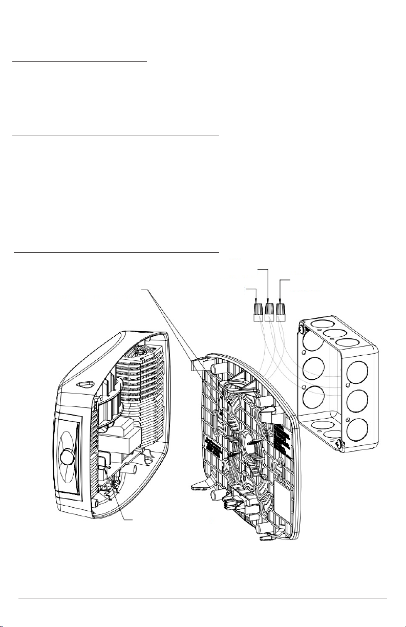
INSTALLATION INSTRUCTIONS
1. Remove the cover by pressing the snap tabs marked “Press” [FIGURE]
2. Remove the appropriate knockouts on the mounting plate for the selected junction box.
3. Connect the xture wires to the power supply wires using the provided wire nuts. The wiring
is as follows [FIGURE]
9W Unit
Orange Wire – 277 VAC Input
Black Wire – 120 VAC Input
White Wire – Neutral
16W Unit
Black Wire – 120-277VAC Universal Input
White Wire – Neutral
Blue Wire – Remote Lamp Negative (–)
Yellow Wire – Remote Lamp Positive (+) (9.6VDC)
4. Attach the mounting plate to the junction box via the previously established holes.
5. Check the mounting plate for level before moving on.
6. Snap the front housing onto the back housing by laying the housing on the top snaps, then
rotating into the bottom snaps. [gure]
a. When snapping the unit together, ensure that the plug and mating connector are
aligned so that the unit receives power.
7. Adjust the lamp heads down and outward for the designed emergency illumination.
WALL MOUNT BACK POWER FEED
1. Remove front cover by inserting at blade screwdriver into slots.
2. Remove appropriate knockout in back plate and mount back plate to J-box
3. Knockout in center of back plate and feed wires through the hole.
4. Securely backplate to J-box.
5. Connect the xture wires to the power supply wires using the wire nuts provided. Connect the
white wire to neutral, connect the black wire to the hot lead. Cap the unused lead. Press the
wires into the J-box (Refer to Wiring diagram below).
6. Connect remote wires if this item with remote capability. Refer to below instructions for
remote wires.
7. Plug battery male connector into battery female connector on PCBA.
8. Snap the front cover on the back plate.
9. Restore power and press test button. LED heads will turn on.
10. Adjust the lamp heads direction as needed.
MOUNTING INSTRUCTIONS
EVENLITE WWW.EVENLITE.COM Z410201
4 ISOLITE WWW.ISOLITE.COM REV-1 20230724
WALL MOUNT (TOP POWER FEED)
1. Open front cover and remove top knockout on top ange of xture.
2. Secure conduit (or surface raceway) to knockout and feed wires.
3. Remove appropriate knockout on back plate and mount to wall.
4. Refer to above 5-10 steps in Wall Mount-Back Power Feed.
CONNECTING REMOTE POWER HEAD (OPTION 16W)
Connect extended remote wires to remote wires using wire nuts. Yellow is positive (+), blue is
negative(-). Support up to 6 watt of Telesis PRW LED 16-Watt Capacity with 2 x 5-watt lamps and
up to 6-watt remote capacity.
MAXIMUM MOUNTING HEIGHT (9W UNIT ONLY) = 21 FEET
MAXIMUM MOUNTING HEIGHT (16W UNIT ONLY) = 28 FEET
BATTERY CONNECTION
MOUNTING KNOCKOUTS
ORANGE 277VAC
BLACK 120VAC
WHITE NEUTRAL
WIRING INSTRUCTIONS
AC Only Operation Wiring Instructions (9W Wiring)
EVENLITE WWW.EVENLITE.COM Z410201

ISOLITE WWW.ISOLITE.COM REV-1 20230724 5
AC Only Operation Wiring Instructions (16W Wiring)
MOUNTING KNOCKOUTS
BATTERY CONNECTION
WHITE NEUTRAL
BLACK 120-277VAC
BLUE REMOTE LAMP NEGATIVE
YELLOW REMOTE LAMP POSITIVE
(9.6 VDC)
REMOTE LAMP HEAD WIRING (16W UNIT ONLY)
NOTE: When remote lamps heads are used, the main housing will reduce light output to 10W to
provide power to the remote lamp heads.
NOTE: Only use approved multi-voltage lamp heads with the unit.
Prior to mounting the unit to the junction box as listed in step 4 above, attach the remote lamp
wires to the blue and yellow wires via wire nuts.
When installing remote lamps, ensure that adequate space is provided between the line voltage
wires and the remote lamp wires [FIGURE]. Always wire the devices in accordance with local and
national electrical codes.
OPERATIONS
All units are furnished with self-diagnostics, which will automatically perform a functional test
every 28 days. If a manual test is required, the method is as follows:
For a 30 second Functional Test
1. Press and hold the test button for 1 second.
2. The unit will run a 30 second test.
a. While in test mode the LED indicator will ash green.
For a 90-minute Duration Test
1. Press and hold the test button for 4 seconds.
2. The unit will run a 90-minute duration test.
a. While in test mode the LED indicator will ash green.
b. If the battery charge is insucient, the 30 second functional test will be performed instead.
NOTE: The lamp current will be calculated upon the running of the rst self-diagnostic test.
Subsequent self-diagnostics checks will verify the lamp current against the initial measurement.
EVENLITE WWW.EVENLITE.COM Z410201

6 ISOLITE WWW.ISOLITE.COM REV-1 20230724
LAMP ADJUSTMENT
EVENLITE WWW.EVENLITE.COM
This Emergency Light has Two Adjustable LED lampheads. Each lamphead can be tilted down up
to 20° and rotated up to 90° away from the wall.
TILT HEAD ASSEMBLY
LAMPHEAD
ROTATION
Z410201
This unit meets the requirements of NFPA 101 for Periodic Testing of Emergency Lighting Equipment.
It provides visual indication of unit malfunctions including:
Battery Fault
Charger Fault
Transfer Fault
Lamp Fault
Door Fault
SELF-TEST
An automatic self-test and diagnostic function will be performed every 28 days. A load test will
be performed for 30 seconds checking for a lamp, battery or transfer fault. On every fourth test,
the load test will follow a door function test, during which the door will open for approximately
1 second and then close, without the lamps turning on. This automatic self-test and diagnostic
function will be performed only if the battery is fully charged. If not, the test will automatically
reschedule. The charger function is monitored continuously.
DEFEAT MONTHLY DIAGNOSTICS TESTING
To defeat the self-diagnostic feature of the unit, please contact the factory.
USER-TEST
A manual USER-TEST can be performed for 30 seconds or 90 minutes. By pushing the “TEST”
Switch for 1 second, the door will open and the lamps will illuminate for 30 seconds. If the
“STATUS” indicator shows GREEN indicating a fully charged Battery and the Switch is pushed for 4
seconds, the door will open and the lamps will illuminate for 90 minutes. If the Battery is not fully
charged, the 30 second test will run. In either mode, the USER-TEST can be cancelled by pushing
and holding the “TEST” Switch for 1 second after the lamps con on.
LAMP LOAD LEARN
The self-diagnostic system “learns” the lamp load during the rst test. Subsequent tests compare
the measured lamp load during the test to the learned lamp load values.
CLEARING FAILURE INDICATIONS
Failure indications can be cleared by correcting the indicated fault and pushing and holding the
“TEST” Switch for 1 second.
STATUS INDICATIONS
Status indications for the self-testing / self-diagnostic system are shown on the following page.

ISOLITE WWW.ISOLITE.COM REV-1 20230724 7
SELF-TESTING / SELF-DIAGNOSTICS
This unit meets the requirements of NFPA 101 for Periodic Testing of Emergency Lighting Equipment.
It provides visual indication of unit malfunctions including:
Battery Fault
Charger Fault
Transfer Fault
Lamp Fault
Door Fault
SELF-TEST
An automatic self-test and diagnostic function will be performed every 28 days. A load test will
be performed for 30 seconds checking for a lamp, battery or transfer fault. On every fourth test,
the load test will follow a door function test, during which the door will open for approximately
1 second and then close, without the lamps turning on. This automatic self-test and diagnostic
function will be performed only if the battery is fully charged. If not, the test will automatically
reschedule. The charger function is monitored continuously.
DEFEAT MONTHLY DIAGNOSTICS TESTING
To defeat the self-diagnostic feature of the unit, please contact the factory.
USER-TEST
A manual USER-TEST can be performed for 30 seconds or 90 minutes. By pushing the “TEST”
Switch for 1 second, the door will open and the lamps will illuminate for 30 seconds. If the
“STATUS” indicator shows GREEN indicating a fully charged Battery and the Switch is pushed for 4
seconds, the door will open and the lamps will illuminate for 90 minutes. If the Battery is not fully
charged, the 30 second test will run. In either mode, the USER-TEST can be cancelled by pushing
and holding the “TEST” Switch for 1 second after the lamps con on.
LAMP LOAD LEARN
The self-diagnostic system “learns” the lamp load during the rst test. Subsequent tests compare
the measured lamp load during the test to the learned lamp load values.
CLEARING FAILURE INDICATIONS
Failure indications can be cleared by correcting the indicated fault and pushing and holding the
“TEST” Switch for 1 second.
STATUS INDICATIONS
Status indications for the self-testing / self-diagnostic system are shown on the following page.
EVENLITE WWW.EVENLITE.COM Z410201

8 ISOLITE WWW.ISOLITE.COM REV-1 20230724
STATUS INDICATIONS
*For 90-minute User Tests, wait for full charge.
For 30 second User Test, try again after an hour of charging.
REMOVAL OF SPLICE BOX COVER
Splice Box Cover can be removed from backbox by prying forward the top, front ange of the
backbox with a at blade screwdriver.
BATTERY - The battery supplied in this unit requires no maintenance. It will be periodically tested
by the SELF-TESTING / SELF-DIAGNOSTIC system according to the requirements of NFPA 101. If
battery replacement is required, replace using the BATTERY INSTALLATION procedure.
For the 9W Curve, the unit will be supplied with a Nickel Metal Hydride (Ni-MH) battery, replace
with part number B350007 only.
For the 16W Curve, the unit will be supplied with a Lithium Iron Phosphate (LiFePO4) battery,
replace with part number B410001 only. Do not interchange battery types.
Used batteries may not be disposed of in the municipal solid waste stream. Arrangements for
recycling batteries can be made by contacting www.call2recycle.org
MAINTENANCE
STATUS DISPLAY FUNCTION ACTION
Continuous Green Battery Float Charging None
Continuous Red Battery Bulk Charging Wait for Charge Completion
Flashing Green In Test Mode Wait for Test Completion
Alternate Red and Green Insucient Charge
For User Test
Wait for Charge Completion
Red
One Blink (ON/Pause)
Transfer System Failure Factory Service Required
Red
Two Blinks (On/Pause)
Battery Failure Verify Battery Connections/
Replace Battery
Red
Three Blinks (On/Pause)
Charger Failure Factory Service
Red
Five Blinks (On/Pause)
Lamp Failure Replace Lamps,
Factory Service
EVENLITE WWW.EVENLITE.COM Z410201

ISOLITE WWW.ISOLITE.COM REV-1 20230724 9
SETUP AND OPERATION
REAPPLY POWER AND NOTIFY THE AUTHORITY HAVING JURISDICTION
TROUBLESHOOTING
PROBLEM
Lamp failure indicated when there’s no lamp failure.
SOLUTION
The product may have calculated a larger lamp load when the lamp load calculation was
performed at the rst self-diagnostic function test. To reset the lamp failure status, remove
the unit from the wall, disconnect the battery, wait 30 seconds, reconnect the battery,
reinstall the unit onto the mounting plate.
The lamp current calculation will be performed on the next function test.
CCEA APPROVAL- Approval for CCEA City of Chicago Environmental Airspace is available as
a factory option.
Z410201
EVENLITE WWW.EVENLITE.COM

SAVE THESE INSTRUCTIONS
2575 Metropolitan Drive • Trevose, PA • 19053 U.S.A
Telephone: (215) 244-4204 • Fax: (215) 244-4208
Z410201
Table of contents
Other Evenlite Lighting Equipment manuals


Popular Lighting Equipment manuals by other brands


Blue Wave
Blue Wave NP5872 Assembly instructions

Lightmybricks
Lightmybricks LEGO Kessel Run Millennium Falcon 75212 installation instructions

sunjoe
sunjoe 24V-LGT500-LTE Operator's manual

HOMEDEPOT
HOMEDEPOT 29523 Use and care guide

Integratech
Integratech UBOAT HO manual

HQ Power
HQ Power HQLP10010 user manual

LIVARNO LUX
LIVARNO LUX 345123 2004 Operation and safety notes

LIVARNO LUX
LIVARNO LUX 100656 Operation and safety notes

Road Shock
Road Shock 95059 Installation and operation instructions

Claypaky
Claypaky AXCOR WASH 300 instruction manual

North Light
North Light XH-B01020 instruction manual

COLORKINETICS
COLORKINETICS ReachElite Powercore 100 installation instructions