Evenlite RAZOR-3 SERIES User manual

RZR3 DIE CAST ALUMINUM EXIT SIGN / FIXTURE
INSTALLA
TION AND OPERATING INSTRUCTIONS
IMPORTANT SAFEGUARDS
When using electrical equipment, basic safety precautions should always be followed including the following:
Page 1
Z410139 Rev F
RAZOR-3 SERIES
SAVE THESE INSTRUCTIONS
CONSERVER LA FICHE D’INSTRUCTION
2575 Metropolitan Drive • Trevose • PA 19053 U•S•A
Telephone: (215) 244-4204 • Fax: (215) 244-4208
READ AND FOLLOW ALL SAFETY INSTRUCTIONS:
1. DO NOT use outdoors.
2. DO NOT mount near gas or electric heaters.
3. Equipment should be mounted in locations and at heights where it will not be
readily subject to tampering by unauthorized personnel.
4. The use of accessory equipment is not recommended by the manufacturer.
Use of such equipment may cause an unsafe condition.
5. DO NOT use this equipment for other than intended use.
6. Conduct periodic visibility tests in accordance with the applicable installation
code (such as NFPA 101).
7. Supply connections MUST be made inside the junction box.
8. Install using recommended junction box ONLY.
9. Servicing of this equipment should be performed by a qualified service
personnel.
10. Install sign indoors only where not exposed to direct unfiltered sunlight, liquid
spray or temperatures outside of the range of 10oC to 40oC.
11. Before installing unit, disconnect power at breaker panel.

Page 2
Z410139 Rev F
RAZOR-3 SERIES
RZR3 DIE CAST ALUMINUM EXIT SIGN / FIXTURE
TABLE OF CONTENTS
Section 1.0 Installation Preparation Page 3
1.1 Knockouts and Chevrons Page 3
1.2 Transformer Wiring Page 4
Section 2.0 Installation Options Page 5
2.1 Back Mount Installation Page 5
2.2 Canopy & Top Mount Installation Page 6
2.3 End Mount Installation Page 7
Page 8Section 3.0 Master-Remote Sign Configuration
Page 11
5.1 Flasher/Fire Alarm Page 11
5.2 Remote Exit and Lamp Operation Page 11
5.3 Infra Red Remote Testing Page 11
Section 4.0 Diagnostics Page 10
5.1 Non-Self Testing/Diagnostic Models Page 10
5.2 Self Testing/Diagnostic Models Page 10
Section 5.0 Options

SECTION 1.0: Installation Preparation
This Exit Sign is designed to be mounted to a junction box (supplied by others). It can be either back,
top or side mounted. The single face unit back mounts to a standard 4” Square (4S) junction box.
Dual circuit options will require a deep junction box.
Z410139 Rev F Page 3
DEPTH
4.00
4.00
3 ⅜
3 ⅜
4 ¾
Between
mounting
holes
Figure 1: Junction box dimensional outline
DEPTH:
Standard J-box Depth = 1
½” Deep J-Box Depth = 2 ⅛”
SECTION 1.1: Knockouts and Chevrons
Figure 2: Opening the sign
1. Open enclosure and separate panels using a flat blade screw driver (as shown below).
To separate the housing, insert a flat blade
screwdriver into the 4 slots on the edge and
rotate the blade gently so that the housings
snaps apart. Repeat on all sides before
pulling apart.
2. Support rear panel on spacers and punch out appropriate knockouts to fit junction box.
Figure 3: Rear Panel Knock Outs
Junction Box Knockouts
Knockout for lead
wires to sign.
Knockouts for remote
connection wires

Z410139 Rev F Page 4
3. To remove directional indicators, remove light guide assembly and diffusers and set aside.
Support front cover and knock out desired indicator(s).
Knock out desired directional
indicators (chevrons) supporting
the front panel as shown.
Figure 4: Removing the
directional indicators (chevrons)
AC Single Circuit Input: The transformer plate assembly will be provided assembled as shown
below. Connect lead wires to feed wires in 1 ½” deep junction box.
Figure 5: Single Circuit Application - Lead wire connections to transformer
Secondary wires to Exit Sign
Transformer
Green
Ground White
Neutral
Black
120V
Orange
277V
Cap unused
primary wire
Protected Earth
Ground Screw
Cable clamp
(strain relief)
Transformer plate
Circuit 1 Connection
Secondary wires to Exit Sign
Orange
277V
White
Neutral
Black
120V
Green
Ground
Circuit 2 Connection
Orange
277V
Cap unused
primary wire
Cap unused
primary wire
Protected Earth
Ground Screw
Transformer Circuit 1
Transformer Circuit 2 Green
Ground
White
Neutral
Black
120V
AC Dual Circuit Input: Utility Power and Emergency Power can be connected to EITHER
transformer. Mixed voltages may be used. (Example:120V Utility Power, 277V Emergency Power)
Figure 6: Dual Circuit Application - Lead wire connections to transformers
SECTION 1.2: Transformer Wiring
***Before installing unit, disconnect power at breaker panel***
Transformer
Plate
NOTE: When
wiring both
Utility and
Emergency
Power, a 2 ⅛”
deep junction
box is required
per NEC Code.

Z410139 Rev F Page 5
SECTION 2.1: BACK MOUNT INSTALLATION (SINGLE FACE SIGN)
Figure 7: Back Mount Installation
2X screws
supplied with
J Box
Filler Plate (See Detail B)
Front Panel
with diffuser
Light Guide Assy w/
Photo-luminiscent
Panel
Rear Panel
Green film
(Transparent)
white reflector (far side)
Optional Security Enclosure
(Single Face)
Refer to Instructions supplied with
security enclosure for full
assembly details.
Detail A
White reflector
Transformer lead wires
Transformer Connectors
Remote
Option
Connector
Used in all other applications
“Thicker” side clip is supplied when a
single face security enclosure is
ordered. Outline shown below is used
in all other applications.
Detail B
transformer secondary leads
SECTION 2.0: INSTALLATION OPTIONS
The Razer 3 Series has several different Mounting options available to fit a wide variety of applications.
Those options are:
1. Back Mount Installation (See Section 2.1)
2. Canopy/Top Mount Installation (See Section 2.2)
3. End Mount Installation (See Section 2.3)
1. Secure spider plate to junction box. Route transformer’s secondary leads through center
knockout of the rear panel.
2. Place the filler plates in rear panel as per Detail B.
3. Terminate transformer leads to light guide assembly, per Detail A below.
4. Route wires between the rear panel and the white reflector. The wires should not be visible when
looking at the sign from the front face.
5. Snap on Front Panel with the colored diffuser.

Z410139 Rev F
SECTION 2.2: CANOPY & TOP MOUNT INSTALLATION
(SINGLE OR DOUBLE FACE SIGNS)
Page 6
Figure 8: Canopy mount Installation (Top/ Ceiling Mount)
(2) PPH #6-32 x 5/8” long screws
Canopy to 7UDQVIRUPHU Plate
(supplied with Exit Sign)
&DQRS\
Secure transformer plate
assy to J-box with screws
provided with J-box.
Standard 4 inch J Box
Not supplied with sign.
(2) PPH #6-32 x 3/8” long Screws Canopy to
Exit Sign (supplied with Exit 6ign)
SCREW LENGTH IS CRITICAL.
DO NOT SUBSTITUTE, MAY CAUSE
DAMAGE TO INTERNAL COMPONENTS.
Terminate Transformer
secondary wires to Sign
(leads are shown at an
exaggerated length for
clarity. Actual leads are
shorter).
Optional Security Enclosure
Must be installed prior to
securing canopy to sign.
1. Secure transformer plate to junction box. Guide transformer secondary leads through canopy
and connect to sign.
2. Secure canopy to sign and then fasten to spider plate. If an optional security cover will be
utilized, it must be assembled to sign prior to securing the canopy to the sign.
Transformer Plate
Not supplied with sign.

Z410139 Rev F
SECTION 2.3: END MOUNT INSTALLATION
Page 7
Figure 10: Left vs. Right End Mount
Figure 11: Reversing Light Guide Assembly - Right End Mount Configuration
(Single Face Units only)
Open sign as described in Figure 2. Remove the
Light Guide assembly. Remove the white card by
grasping near the bottom and pulling outward.
Holding the light guide in the same orientation, install
the white card on the reverse side, bending it slightly
to install the 4 tabs into the corresponding slots.
Left End Mount Right End Mount
Please See Figure 11 for configuration
of Single Face Units only
(2) PPH #6-32 x 5/8” long screws
Canopy to Spider Plate Assy
supplied with Exit Sign
Transformer
Plate
Standard 4 inch J Box
Not supplied with sign.
Secure transformer plate
assy to J-box with screws
provided with J-box.
(2) PPH #6-32 x 3/8” long Screws
Canopy to Exit Sign
supplied with Exit sign
SCREW LENGTH IS CRITICAL.
DO NOT SUBSTITUTE.
Terminate Transformer
secondary wires to Sign.
Figure 9: Left End Mount Installation
Canopy

Z410139 Rev F Page 8
SECTION 3.0: MASTER-REMOTE SIGN CONFIGURATION
Master Sign:
Canopy End
Mount
Remote Sign
Back Mount
The Master - Remote product (RZMR3) is
supplied with 2 signs. The master sign
(Figure 13) is provided with a system
battery, spider plate assembly (for power)
and an option connector used to connect
the two signs.
The remote sign (Figure 14) is assembled
in the same manner as the master sign,
without a spider plate assembly. An option
connector is also installed in the remote
sign for interconnection to the master sign.
Interconnect the signs with a 2-conductor
cable(20 awg minimum) per the National
Electric Code, observing correct polarity.
The run should be a distance of 50 feet or
less.
To install remote lamp (3.6V,2W max - not
shown), the option connector is installed
similarly in the master sign as shown in
Figure 13. Terminate remote lamp leads to
the option connector in mating pins labeled
“Remote Lamp”. Remote Lamp max
mounting height to be 11ft or the
equivalent.
Figure 12: Master - Remote Sign Example
Figure 13: Master Sign (Canopy-End Mount) option connector
Master Sign
Transformer Plate assembly secured to JBox
Note: Wires from the transformer are not shown for clarity
Refer to Figure 9 for connecting transformer wire to sign.
Screws to secure canopy to spider
plate (Supplied with Sign)
Canopy
Screws to secure canopy to sign(supplied with sign)
Option Connector
Remote Exit
Terminations
Route remote wires between canopy and
transformer plate, outside of the junction
box
Install Remote Connector so
the white area indicated
above corresponds to the
white marking on the flex
PCA within the sign.
Fire Alarm
Remote Lamp
Remote Exit
The master sign can be top mounted or side mounted (left or
right) by mounting the canopy in the same location as the side
clips. Refer to Figure 8 for top canopy mount.

2X screws
supplied with
J Box
Filler Plate
Front Panel
Light Guide Assy
White Reflector (far side)
Route remote wire from master sign to remote sign via the knock out in the rear panel. The
remote sign can be mounted to a junction box (as shown) or secured safely to the wall using
anchors. The remote option printed circuit assembly should be installed into the sign as shown
below. The text legend on the PCA should be visible when looking at the rear of the light guide
assembly.
Figure 14: Remote Sign (Back Mount) Installation
Knockout for
remote option
wires
Remote
Exit
- +
Remote
Lamp
- +
Fire
Alarm
- +
NOTE:
This product contains Ni-MH batteries. Used batteries may not be disposed of in the
municipal solid waste stream. Ni-MH batteries must be recycled or disposed of properly. For
information on local recycling drop-off
points, phone toll free 1-800-BATTERY (1-800-228-8379).
Supplemental
Battery (1)
Supplemental
Battery (2)
Figure 15: System / Remote Lamp Battery Replacement
System Battery
J1 J2
J3
Wire channel for
battery leads on
opposite side of
midframe. Shown
as dashed lines
for clarity.
System Battery to J3
Supplemental
Battery (2) to J1 Supplemental
Battery (1) to J2
The System battery is supplied with the sign for emergency backup configurations.
Supplemental batteries are provided with the sign when Remote Capacity/ Lamp is ordered.
Z410139 Rev F Page 9
Connectors on
farside
Text legend on PCA
(Refer to Figure 13 & 16)
Rear Panel

TABLE: DIAGNOSTIC STATUS INDICATIONS
STATUS DISPLAYFUNCTION ACTION
Battery in Float/Trickle Charge
Battery High Charging
In Test Mode
Insufficient Charge for User Test
Transfer System Failure Battery
Failure
Charger Failure
Lamp Failure
None
Wait for Green Status
Wait for Test to Complete
Wait for Full Charge
Factory Service
Check Connections/Replace Battery
Factory Service
Check Remote Connection/ Factory Service
Continuous Green
Continuous Red
Flashing Green
Alternate Red and Green
Red - One Blink ON / Pause
Red - Two Blinks ON / Pause
Red - Three Blinks ON / Pause
Red - Four Blinks ON / Pause
SECTION 4.0: DIAGNOSTICS
For units with Self-Testing/ Self Diagnostics option, refer to the section on next page for operating
instructions. Battery back-up units without Self-Testing/ Self Diagnostic option Include a battery
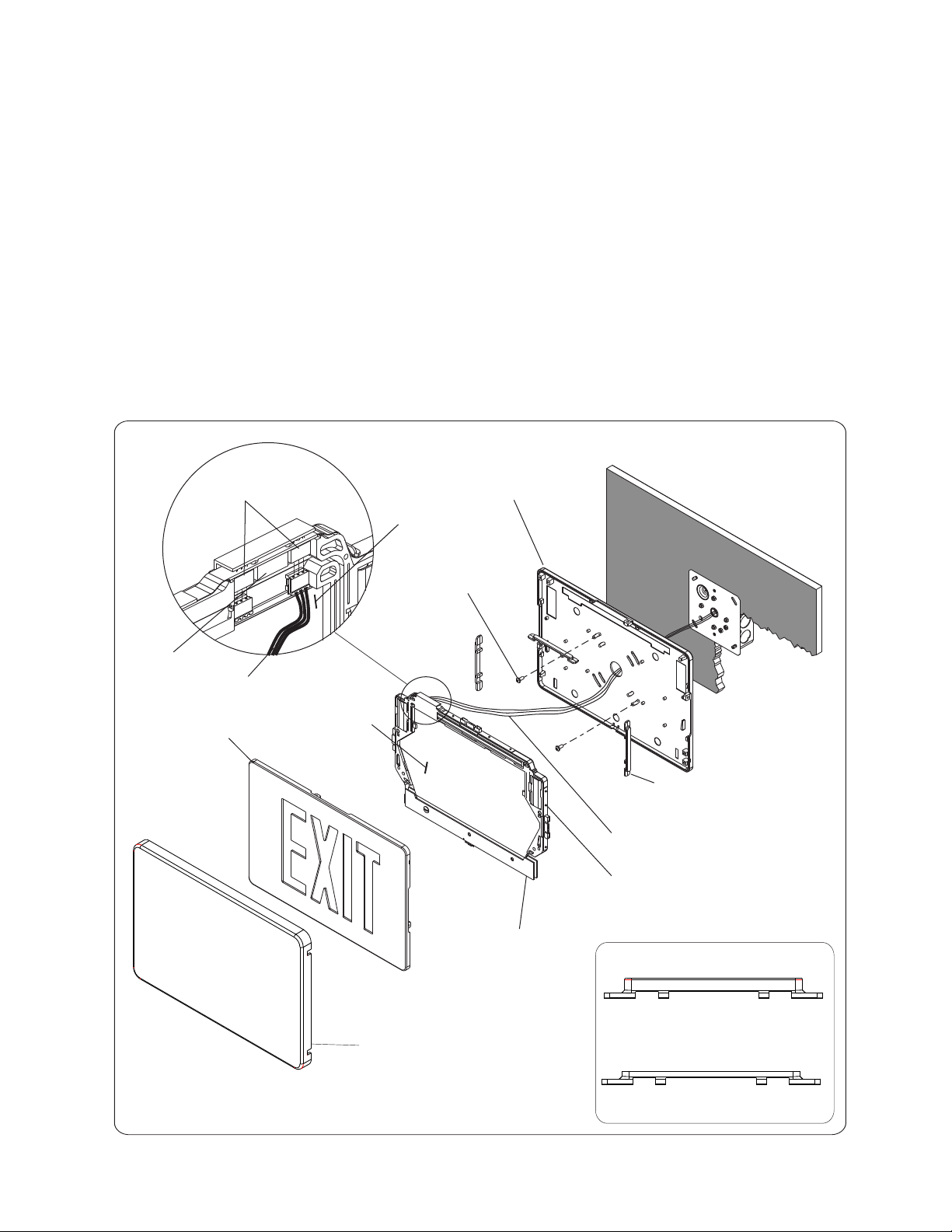
diagnostics system which indicates, via flashing of the indicator light, that the battery needs replacement. If
flashing occurs after a new installation, check that the battery plug is properly inserted into the circuit board
connector (For reference, see Figure 15).
SECTION 4.1: NON-SELF TEST/ DIAGNOSTIC MODELS
To test battery backup units, use test switch to simulate AC power outage. The indicator light will go out, and
the sign will remain lit, indicating transfer to emergency mode. It will remain lit on battery power until switch is
released. Release of switch will automatically restore AC/ Battery charge mode, with indicator light on.
Testing for longer periods is best accomplished by turning off AC circuit power. Signs should be tested in
accordance with National Electric Code and NFPA 101 Life Safety Code Requirements which specify monthly
testing for 30 seconds and yearly testing for 90 minutes. Note that the batteries will take some time to reach
full charge after a prolonged test, and that the unit cannot provide full duration operation should a real power
outage occur before the batteries have had an opportunity to reach full charge. It is recommended that long
duration tests be limited to once yearly, and be conducted when the area will be unoccupied afterwards.
SECTION 4.2: SELF TESTING/ SELF DIAGNOSTIC MODELS
The unit meets the requirement of NFPA 101 for Periodic Testing of Emergency Lighting Equipment. It provides
visual indication of unit malfunctions including: Battery Fault, Charger Fault, Transfer Fault, Lamp Fault
SELF TEST
The unit will perform a self-test and diagnostic function at least once every 28 days. The self test will
disable the charger and turn on the LEDs for 30 seconds to check the lamp load, battery and transfer
function. The test will be performed only if the battery is fully charged. If not, the test will automatically
reschedule. The charger function is monitored while AC is applied.
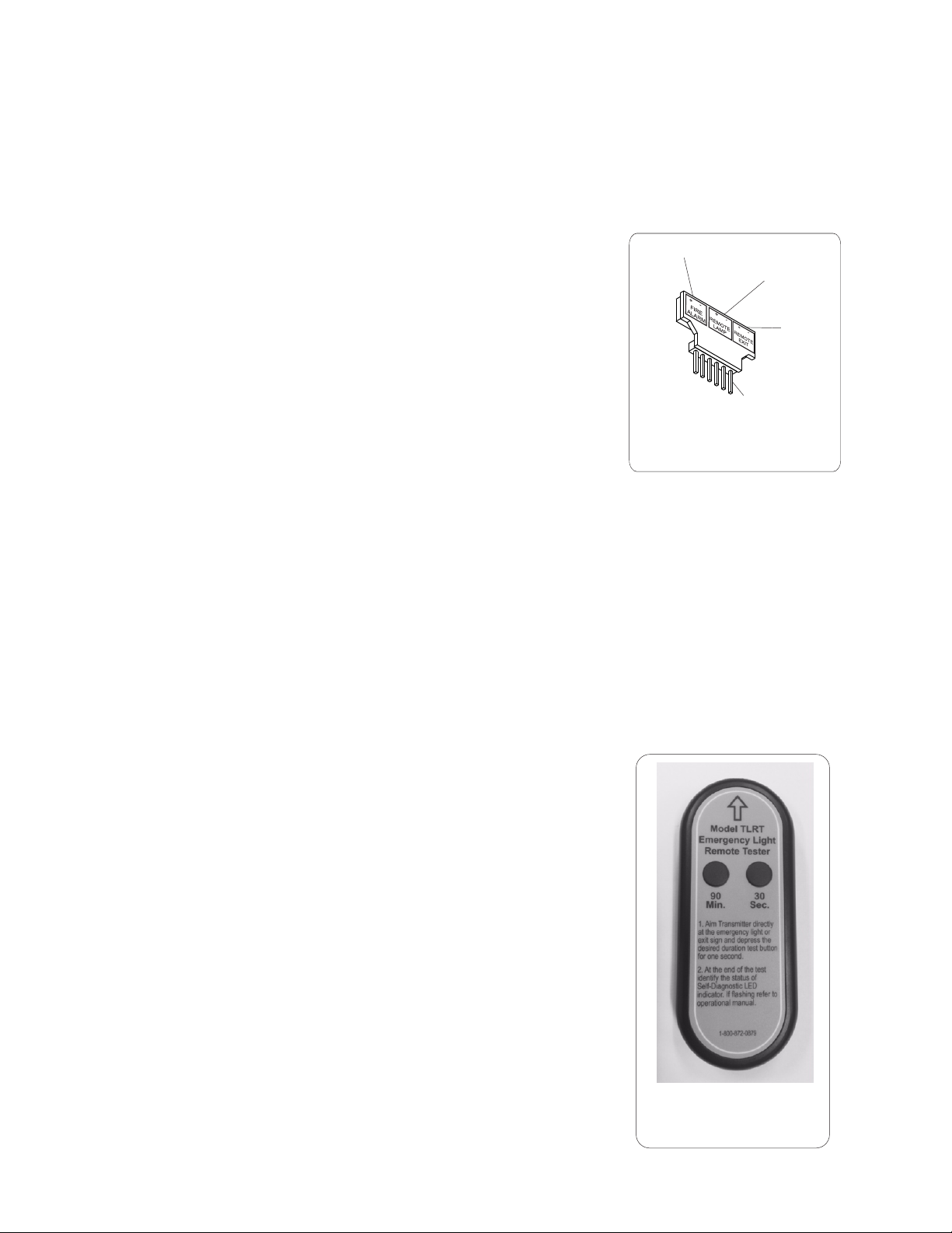
USER TEST
A user-test may be performed at any time the status display is continuous green. On initial power-up, it
could take up to 72 hours for the status display to reach continuous green. With a fully charged battery,
pressing the test switch momentarily will initiate a 30 second test. Pressing the test switch continuously for
4 seconds and releasing it will initiate a 90 minute test.
Either Test can be cancelled by pressing the test switch again for 1 second.
After installation is complete, reapply power and notify the authority
having jurisdiction.
Z410139 Rev FPage 10

To Sign
Fire Alarm
Remote Lamp
Remote Exit
Figure 16: Option
Connector
Page 11
Z410139 Rev F
To activate TRANSMITTER, remove tab from back of device.
The USER-TEST can be performed up to 20 feet away using the
optional “INFRA RED REMOTE TESTING TRANSMITTER”.
By aiming the TRANSMITTER (Figure 17) at the legend face, and
pushing either the “30 SECOND” or “90 MINUTE” button for 1 second,
the TRANSMITTER can initiate or cancel “30 SECOND” or “90
MINUTE” user tests.
Figure 17: Remote
Transmitter
AC Only and Battery Back up emergency signs that are equipped with
the FIRE ALARM SIGNAL MODE FLASH option will automatically flash
in both AC and emergency modes upon application of a fire alarm
signal to the option connector (Figure 16). The fire alarm signal can be
either AC or DC of either polarity, and range from 12 to 24 volts. The
current draw from the fire alarm signal is less than 10 milliamps (mA).
Units that include one of the above options,
are intended for installation in locations where such
features are permitted by local codes.
Flasher Rate: 60 per minute
Duty Cycle: 25%
SECTION 5.0: OPTIONS
SECTION 5.1: FLASHER/ FIRE ALARM
Battery Backup Emergency signs that are equipped with the FLASH in EMERGENCY MODE OPTION
will automatically flash in the emergency mode but not flash on AC operation. AC Only exit signs that
are equipped with the flash option will flash continuously while power is supplied.
SECTION 5.2: REMOTE EXIT AND LAMP OPERATION
The self-diagnostic system “learns” the lamp and remote sign load when the unit reaches it’s first full
charge. It is therefore necessary to have any remote lamp or sign already connected when first
applying AC power. Subsequent self-tests and user-test will compare the actual lamp and sign load to
the “learned” value.
If the remote lamp and sign load is changed once it has been “learned”, it is necessary to disconnect
AC Power at the circuit breaker panel and unplug the internal battery (refer to Figure 15 for details).
Once these are reconnected, the unit will “learn” the new lamp and sign load.
SECTION 5.3: INFRA RED TESTING

THIS PAGE INTENTIONALLY LEFT BLANK
Other manuals for RAZOR-3 SERIES
1
Table of contents
Other Evenlite Lighting Equipment manuals