Everfit BFK SLIM User manual

Ed : 02/17 Rev: 00
INSTRUCTION

3
Stabilizer
Wheel End cap
WheelEndcap
PRODUCT OVERVI
PRODUCT OVERVIEW
Pulse Sensor
Meter
Adjustment Knob
Seat
Handlebar
Rear Frame
Stabilize
r
Right Chain Cover
Left Pedal
Middle Cover
Right Pedal
THEFOLLOWINGTOOLS ARE INCLUDED FOR ASSEMBLY:
Wrench
Allen Wrench (5mm) w/ Screwdriver
Tension Knob
Pull Pin

4
HARDWARE IDENTIFICATION CHART
adyattachedtothepart.
Part Number and Description Qty
44 Carriage Bolt M8x60 4
80 Hex head bolt M8X40 2
57 Acorn Nut M8 4
58 Arc Washer 4
23 Adjustment Knob 1

ASSEM
B
L
YINSTRUCTIONS
RUCTIONS
5
ASSEMBLY INSTRUCTIONS
Place all parts from the box in a cleared area and position them on the floor in front of you.
Remove all packing materials from your area and place them back into the box. Do not dispose of
the packing materials until assembly is completed. Read each step carefully before beginning.
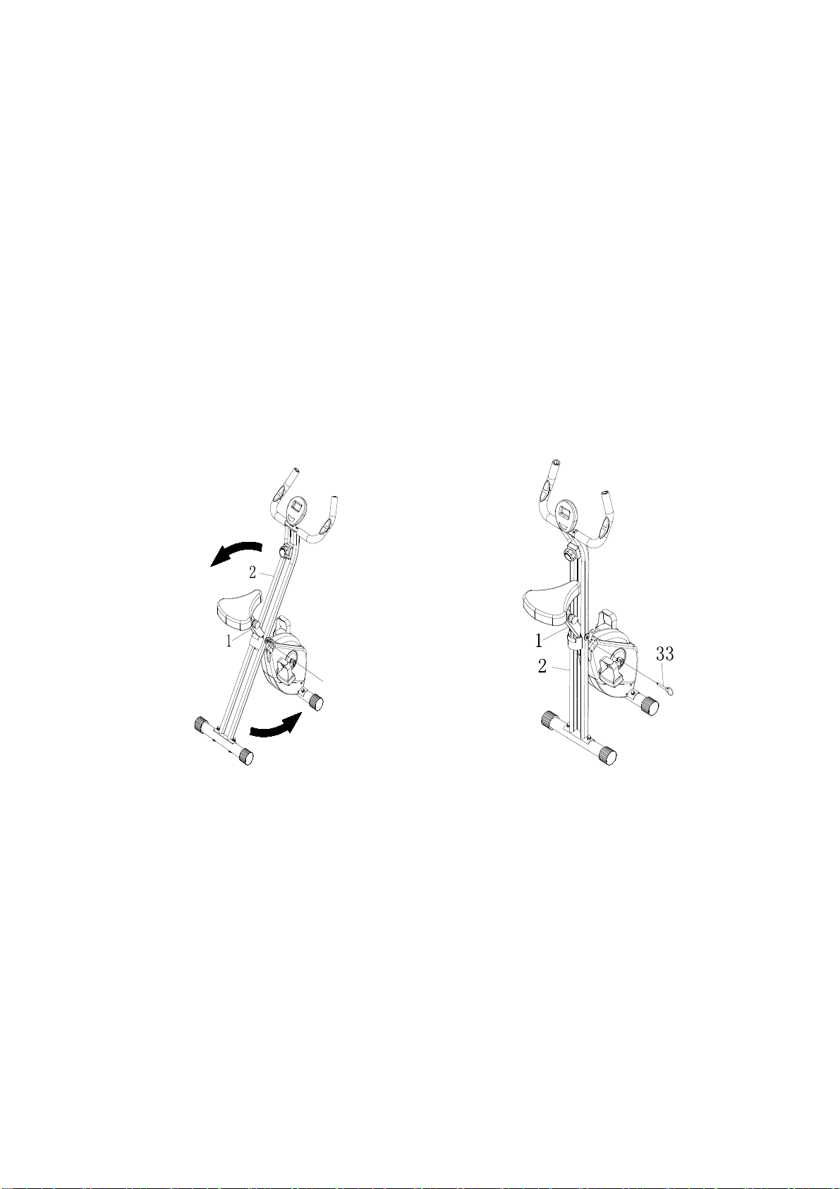
STEP1
Refer to illustration A. Remove the Pull Pin(33) from the REAR FRAME(2). Unfold the REAR FRAME(2)
away from the MAIN FRAME(1). Lock the frame assembly in unfold position by inserting the Pull PIN(33)
into the hole in the REAR FRAME(2).
STEP2
Attached the Front Stabilizer (4) to the Rear Frame (2). Secure with Carriage Bolts M8 (44), Acorn Nuts M8
(57), and Arc Washers M8 (58).
STEP3
Attachthe STABILIZER(4) to the MAIN FRAME(1). Secure with CARRIAGE BOLTS M8(44), ACORN
NUTS (57), and ARC WASHERS M8(58).
A.
1
1

ASSEM
B
L
YINSTRUCTIONS
RUCTIONS
6
STEP4
Attach the SEAT(25) to the SEAT POST(5) with NYLOCK NUTS(79) and LARGE WASHERS
(78). Insert the SEAT POST(5) into the MAIN FRAME(1) and secure with the ADJUSTMENT KNOB(23).
NOTE:
1. Make sure that the pin on the ADJUSTMENT KNOB (23) is inserted into one of the holes in the SEAT POST(5).
2.
The ADJUSTMENT KNOB(23) should be screwed in tight to make the SEAT POST(5) securely in the MAIN
FRAME(1).
25

ASSEM
B
L
YINSTRUCTIONS
RUCTIONS
7
STEP5
Insert the wire(13) of Handlebar (3) into the Rear Frame (2),then secure the handlebar on the
Rear Frame (2) with Hex Head Bolts M6 (80), and insert the Meter (11) onto the iron sheet of
Handlebar (3), then connecting wire (17) and connector (41), connecting wire(13) and Meter
wire(77).
77

ASSENBLY INSTRUCTIONS
8
STEP6
Thread the Left Pedal (27) to the Left Crank (28) as shown. Tighten the pedal securely. Refer to
the detail view below. Repeat on the Right side in order to attach the Right Pedal (35) to the Right
Crank (36).
FUNCTION INSPECTION:
Visually inspect the Bike to verify that assembly is as shown in the above illustration.
Check the function of the Bike by turning the c rank s lowly through one complete revolution to verify that
the drive train functions properly. Adjust the TENSION KNOB (39) and verify that it functions properly and
the resistance changes.

OPER
A
TIONALINSTRUCTIONS
9
T I M E
S P E E D
DISTANCE
CALORIES
ODOMETER
S C A N
PULSE
M O D E
SET
RESET
OPERATIONAL INSTRUCITONS
USING THE FITNESS METER
POWER ON: Pedal movement or press the button.
POWER OFF: Automatically shuts off after four minutes of inactivity.
MODE BUTTON:
Press to select display functions, including SCAN, TIME, SPEED, DISTANCE,
CALORIES, ODOMETER, and PULSE.
Press and hold for two seconds to reset all functions to zero, except ODOMETER.
FUNCTIONS:
SCAN: Automatically scans each function of TIME, SPEED, DISTANCE, CALORIES,
ODOMETER, and PULSE in sequence, display changes every six seconds. Press and release the button until
“SCAN” appears on the display.
TIME: Displays the time from one second up to 99:59 minutes.
SPEED: Displays the current speed from zero to 999.99 meters.
DISTANCE: Displays the distance from zero to 99.99 meters.
CALORIES: Displays the calories burned from zero to 999.9 Kcal. The calorie readout is an estimate for an average
user. It should be used only as a comparison between workouts on this unit.
ODOMETER: Displays the total accumulated distance you have traveled from zero to 999.9 meters. The total
accumulated distance is retained when the meter is turned off.
PULSE: Displays your pulse rate in beats per minute. To display pulse, select the PULSE mode and grasp the pulse
sensors on the handlebar, one in each hand. The heart icon will begin flashing when the FITNESS METER senses
your pulse. Your pulse will be displayed approximately five (5) seconds after the heart icon is displayed. If the heart
icon does not appear, relax your grip or change your grip on the pulse sensors.
NOTE: 1. The meter will shut off automatically after four minutes of inactivity. All function values will be kept. Press
the button and hold it down for two seconds to reset all functions to zero, except ODOMETER.
2.The ODOMETER will be reset to zero after batteries are removed for battery replacement or storage of the unit.
HOW TO INSTALL AND REPLACE BATTERIES
1. Open the Battery Door on the back of the meter.
2. The meter operates with two AAA batteries, the batteries are not included. Refer to the illustration to install or
replace the batteries.
NOTE:
1. Do not mix a new battery with an old battery.
2. Use the same type of battery. Do not mix an alkaline battery with another type of battery.
3. Rechargeable batteries are not recommended.
4. Ultimate disposal of battery should be handled according to all state laws and regulations.
5. Do not dispose of batteries in fire.

OPER
A
TIONALINSTRUCTIONS
10
23
5
1
LOAD ADJUSTMENT
To increase the load, turn the TENSION KNOB(39) clockwise.
To decrease the load, turn the TENSION KNOB(39) counterclockwise.
There are eight levels for the load adjustment.
39
SEAT ADJUSTMENT
Proper seat adjustment is important.
1. Turn the ADJUSTMENT KNOB(23) to loosen, then pull
the ADJUSTMENT KNOB(23) to release the pin. Slide
the SEATPOST(5) until the SEAT(25) is at the proper
height. Release the ADJUSTMENT KNOB(23) making
sure the pin catches in one of the holes of the SEAT
POST(5) and tighten the ADJUSTMENT KNOB(23).
2. Sit on the seat and place your feet on the pedals. You
should be able to move through a complete pedal stroke
without locking your knees or shifting your hips on the
seat. The seat is too close to the pedals if you have more
than as light bend in your knees at the bottom of the pedal
stroke. The seat is too far from the pedals if you have to
completely straighten your knees at the bottom of the
pedal stroke. Refer to the illustration.
CAUTION:
1. Do not attempt to adjust the seat while you
are on the BIKE
2. Always tighten the ADJUSTMEN TKNOB(23)
After adjusting the seat to a new position.
11
STORAGE
1. To store the BIKE, simply keep it in a clean dry place.
2. To avoid damage to the electronics, remove the batteries before storing the BIKE for one year or more.
3. To move the BIKE, hold the HANDLEBAR and tilt the BIKE onto the Wheels of the Stabilizer at the front.
4. Follow the illustrated process below to fold the BIKE.
A. Remove the PULL PIN (33), fold the REAR FRAME (2) forward. Insert the PULL PIN (33) back into the
REAR FRAME (1) after folding.
B. Remove the PULL PIN(33) from the REAR FRAME(2).Fold the REAR FRAME(2) close to the MAIN
FRAME(1) and lock it in folded position with the PULL PIN(33).
NOTE: Make sure the PULL PIN(33) goes through the holes on both sides of the REAR FRAME(2)
and the tube on the MAIN FRAME(1).
A B
CE
33
The safety and integrity designed into the
BIKE
can only be maintained when the
BIKE
is regularly
examined for damage and wear. Special attention should be given to the following:
1.
Adjust the TENSION KNOB (39) and verify that it functions properly and the resistance changes.
2.
Use a wrench to verify that the pedals are tightened securely. If tightening is required, remember that
the left pedal has left hand threads and is tightened by turning counterclockwise.
3.
Verifythatallnutsandboltsarepresentandproperlytightened.Replacemissingnutsandbolts. Tighten loose
nuts and bolts.
4.
It is the sole responsibility of the user/ owner to ensure that regular maintenance is performed.
5.
Worn or damaged components shall be replaced immediately or the BIKE removed from service until
repair is made.
6.
Keep your
BIKE
clean by wiping it off with an absorbent cloth after use.

P
A
R
TSLIST
14
PRODUCT PARTS DRAWING
59
4
19
44
44
73
76

P
A
R
TSLIST
15
PARTS LIST
No. Description Qty
1 Main Frame 1
2 Rear Frame 1
3 Hand Rail 1
4 Stabilizer 2
5 Seat Post 1
6 Left Chain Cover 1
7 Right Chain Cover 1
8 Middle Cover 1
9 Bushing 1
10 Foam Pad 2
11 Meter 1
12 Handrail Foam 2
13 Wire 2
14 Pulse Sensor 2
15 Sensor Clip 1
16 Bearing Housing 2
17 Meter Transmission Line 1
18 Plastic Bushing 6
19 Plastic Washer Φ10.2*Φ14 2
20 Protection Pad 1
22 End Cap 4
23 Adjustment Knob 1
24 Crank Cap 2
25 Seat 1
26 Shaft 1
27 Left Pedal 1
28 Left Crank 1
29 Flywheel 1
30 V-Ribbed Belt(230J) 1
31 V-Ribbed Belt(240J) 1
32 Pulley w/ Shaft 1
33 Pull Pin 1
34 Bearing Housing cover 2
35 Right Pedal 1
36 Right Crank 1
37 Pulley 1
38 Magnetic Brake 1
39 8 Section Adjustment Knob 1
40 Spring 1
41 Connection Wire 1
42 Ball Bearing (6000Z) 2

P
A
R
TSLIST
16
43 Grommet Plug 4
44 Carriage Bolt M8X60 4
45 Hex Head Round Bolt M8X20 2
46 Eye Bolt M6 2
47 Tension Bracket 2
48 Nylock Nut M6 2
49 Screw, Round Head Self-Tapping ST4.2X16 4
50 Screw, Round Head Self-Tapping ST4.2X16 6
51 Screw, Round Head M4X10 1
52 Screw, Round Head M5X20 1
53 Flat Washer M5 1
54 Screw, Round Head M6X12 8
55 Screw, Round Head Self-Tapping ST4.0x20 2
56 Flat Washer M4 2
57 Acorn Nut M8 4
58 Arc Washer M8 4
59 Nylock Nut M10 1
60 Nut M10 2
61 Nut M10 1
62 Washer M8 2
63 Spring WasherS17 1
64 C Ring Φ10 2
65 Wave Washer S10 1
66 C Ring Φ17.0 6
67 Flange Nut M10 x 1.25 2
68 Idler Shaft 1
69 Pulley Shaft 1
70 Idler Shaft 1
71 Ball Bearing (6200ZZ) 1
72 Ball Bearing (6003ZZ) 4
73 Magnet 1
74 Magnet 6
75 Limited Bracket 1
76 Screw, Round Head Self-Tapping ST4.2X25 1
77 Meter Transmission Line 2
78 Large Washer M8 3
79 Nut M8 3
80 Hex Head Bolt M8X40 2
81 Wrench 1
82 Allen Wrench w/ Screwdriver 1

GARLANDO SPA
Via Regione Piemonte, 32 - Zona Industriale D1
15068 - Pozzolo Formigaro (AL) - Italy
www.evert.it - info@evert.it
Table of contents
Other Everfit Fitness Equipment manuals


Popular Fitness Equipment manuals by other brands


ERGATTA
ERGATTA Rower owner's manual

BLK BOX
BLK BOX 21-0133-0B Owner's manual & quick start guide

Sunny Health & Fitness
Sunny Health & Fitness SF-XF921050 user manual

Gaide Intelligent Technology
Gaide Intelligent Technology GD06 manual

Sunny
Sunny SF-B1110S owner's manual

Batca
Batca LINK LD-5 owner's manual