Everflo EDS90 User manual

EVERFLO STAINLESS UV
UNVENTED HOT WATER CYLINDERS
INSTALLATION AND MAINTENANCE INSTRUCTIONS
ISSUE 3 MAY 2015

01 EVERFLO STAINLESS UV
UNVENTED HOT WATER CYLINDERS
PAGE CONTENT
2 Introduction
3 Storage, Handling & Supply Requirements
3 Component Table
4 Sitting the unit
5 General Installation
7-8 Discharge Arrangement
9 Technical Specications: Slimline - Direct & Indirect
10 Technical Specications: Direct & Indirect
11 Technical Specications: Solar Direct
12 Technical Specications: Solar Indirect
13 Solar Coil Installation
4 Solar High Limit
15 S-Plan Wiring Schematics
16 Y-Plan Wiring Schematics
17 - 18 Pre-Plumbed Wiring Schematics
19 Pre-Plumbed Installation
20 Technical Specications: Pre-Plumbed
21 System Fit Installation
22 Technical Specications: System Fit
23 Commissioning & Servicing
24 Fault Finding & User Instructions
25 - 27 Guarantee - Terms & Conditions
28 Technical Specication
29 - 30 Specication & Performance
31 Benchmark
32 Commissioning Check Sheet
33 Service Record
INTRODUCTION
The EVERFLO STAINLESS UV Unvented cylinder is made from
Duplex Stainless Steel for excellent corrosion resistance.
EVERFLO STAINLESS UV has a strong rust-proofed steel case
and is highly insulated with environmentally friendly foam.
EVERFLO STAINLESS UV is supplied complete with all the
necessary safety and control devices needed to connect
to the cold water mains. All are pre-adjusted. High quality
controls have been selected to combine high ow rate
performance with minimum pressure drop to make EVERFLO
STAINLESS UV perform well in all areas, even those with poor
water pressure.
EVERFLO STAINLESS UV is KIWA approved to show
compliance with Building Regulations G3+L.
Benchmark places responsibilities on both manufacturers and installers. The
purpose is to ensure that customers are provided with the correct equipment
for their needs, that it is installed, commissioned and serviced in accordance
with the manufacturer’s instructions by competent persons and that it meets
the requirements of the appropriate Building Regulations. The Benchmark
Checklist can be used to demonstrate compliance with Building Regulations
and should be provided to the customer for future reference.
Installers are required to carry out installation, commissioning and servicing
work in accordance with the Benchmark Code of Practice which is available
from the Heating and Hotwater Industry Council who manage and promote
the Scheme. Visit www.centralheating.co.uk for more information.
IMPORTANT NOTE TO
THE INSTALLER
Read these instructions before commencing installation.
Unvented cylinders are a controlled service as dened in the
latest edition of the building regulations and should only be
tted by a competent person.
The relevant regulations are: England and Wales – Building
Regulation G3, Scotland – Technical Standard P3, N Ireland –
Building Regulation Part F
After installation the Benchmark check list must be
completed and left, with these instructions, with the
householder for future reference.
IMPORTANT NOTE TO THE INSTALLER
Read these instructions before commencing installation. Unvented cylinders are a controlled service
as dened in the latest edition of the building regulations and should only be tted by a competent
person.
The relevant regulations are: England and Wales – Building Regulation G3, Scotland – Technical Standard
P3, N Ireland – Building Regulation Part F
After installation the Benchmark check list must be completed and left, with these instructions, with
the householder for future reference.
02
EVERFLO STAINLESS UV
UNVENTED HOT WATER CYLINDERS
STORAGE PRIOR TO INSTALLATION
EVERFLO STAINLESS UV should be stored in its original packaging
in an upright position in an area free from excessive damp.
Regulations G3+L.
HANDLING PRODUCT
The EVERFLO STAINLESS UV should be carried upright where
possible. Assessments of risks for carrying the cylinder should
be conducted. Use more than 1 person for carrying where
appropriate. Always follow latest guide lines for lifting techniques,
to avoid injury and damage to the product.
WATER SUPPLY
EVERFLO STAINLESS UV operates at 3 bar (controlled by the inlet
control set) and is capable of delivering over 50 litres per minute.
The high quality inlet control set has been designed to make the
most of the ow rates available, however the performance of any
unvented system is only as good as the mains water supply. The
maximum possible water demand should be assessed, taking
into consideration that both hot and cold services are supplied
simultaneously from the mains.
The water supply should be checked to ensure it can meet these
requirements. If necessary, consult the local water company
regarding the likely pressure and ow rate availability.
If measuring the water pressure, note that a high static (no ow)
mains pressure is no guarantee of good ow availability. In a
domestic installation 1.5 bar and 25 l/min. should be regarded as
the minimum. The maximum mains pressure that the inlet control
set can accept is 12 bar.
Consideration should be given to upgrading existing ½” (15mm)
cold mains pipework to a larger size if the recommended
minimum pressure/ow rate is not being achieved.
ELECTRIC SUPPLY
The EVERFLO STAINLESS UV requires 240 Volt electrical supply for
the standard Incoloy immersion elements. The electrical supply
to each immersion heater must be fused at 13A via a double
pole isolating switch to BS 3456. The cable must be at least
2.5mm2 heat resistant (85°C HOFR) sheathed ex complying to BS
6141:1981 Table 8.
UNPACKING THE UNIT
EVERFLO STAINLESS UV comes complete with the ttings required
to complete the installation. Please see over for component
content list.
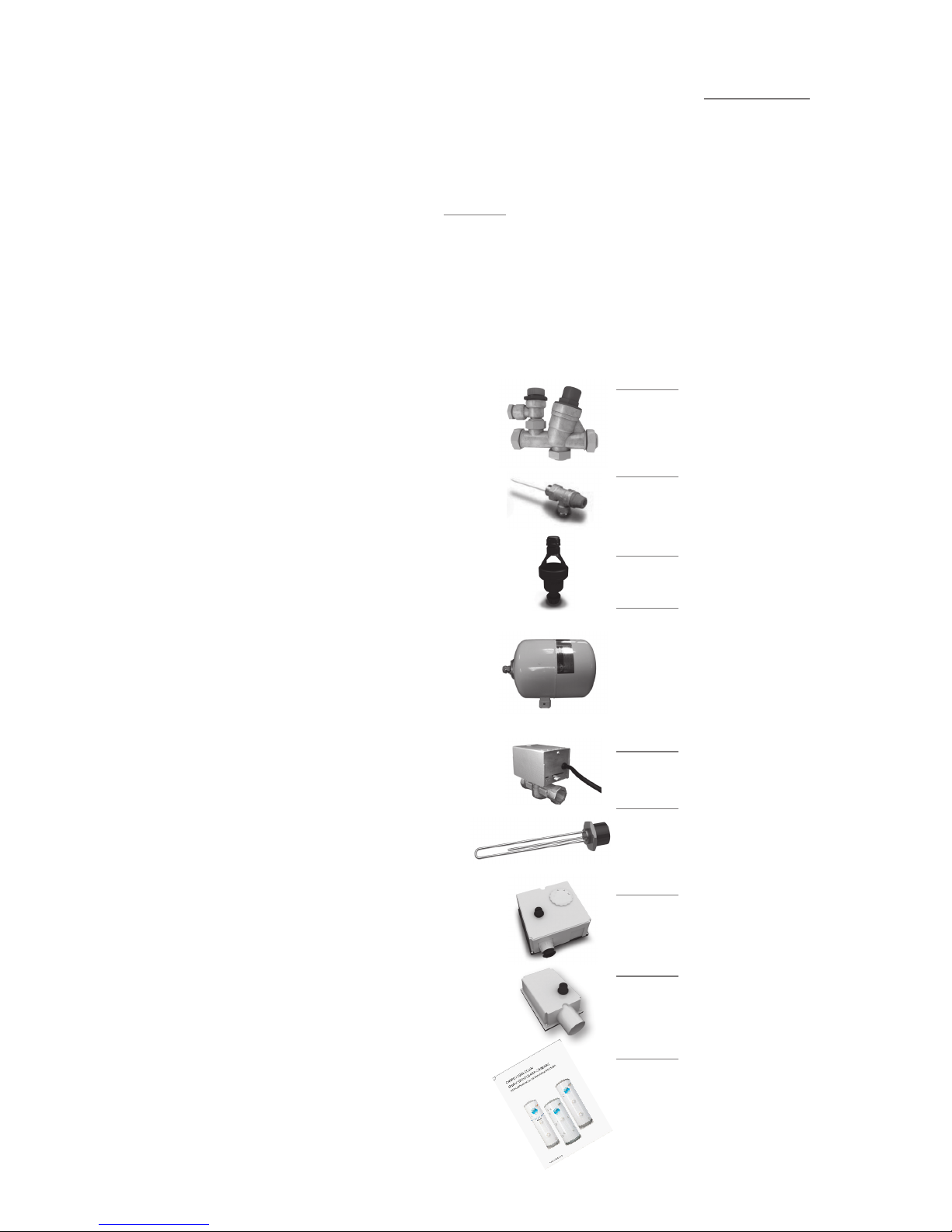
High ow rate inlet control set
TS201-533
Temperature and pressure relief valve
TS202
Acetal tundish 15 x 22 mm
TS3
Incoloy long life
3 kW immersion heater
TS9 - DIRECT TS10 - INDIRECT
Two port valve
TS5
Dual thermostat
US201
High Limit thermostat
TS28
Installation &
Maintenance Instructions
Expansion Vessel
• 60, 90, 120 & 150 ltr units - 12 ltr vessel TS212
• 180, 210 & 250 ltr units - 18 ltr vessel TS219
• 300 ltr units - 25 ltr vessel
TS224

03 EVERFLO STAINLESS UV
UNVENTED HOT WATER CYLINDERS
COMPONENT CONTENT TABLE
Inlet Control set ••••••••••
Temp & Pressure relief valve • • • • • • • • • •
Tundish ••••••••••
Expansion vessel • • • • • • • • • •
Immersion Heater (Direct) • • •
Immersion Heater (Indirect) • • • • • • •
Two Port Valve • • • • • • •
Dual Thermostat • • • • • • •
Single High Limit Stat • • • • • •
Sensor pocket retaining bungs • • • •
Robo-Kit • • • •
TP9000 • • • •
TP5000 • •
Installation & Maintenance
Instructions ••••••••••
Slimline Direct Models (Electric)
Slimline Indirect Models
Direct Models
Indirect Models
Solar Direct Models
Solar Indiect Models
Indirect pre-plumbed
models - 1 zone heating
Indirect pre-plumbed
models - 2 zone heating
Solar indirect pre-plumbed models - 1
zone heating
Solar indirect pre-plumbed models - 2
zone heating
Direct Models (Electric)
Direct Solar Models (Electric + Coil)
Indirect Models (Single Coil)
Indirect Solar Models (Twin Coil)

04
EVERFLO STAINLESS UV
UNVENTED HOT WATER CYLINDERS
SITTING THE UNIT
EVERFLO STAINLESS UV can supply outlets above it or at some
distance from it. Site the unit to minimise “dead leg” distances,
especially to the point of most frequent use.
Outlets above the EVERFLO STAINLESS UV will reduce the outlet
pressure available by 0.1 bar for every 1m of height dierence. The
unit should be protected from frost. Particular care is needed if
sitting in a garage or outbuilding. All exposed pipework should be
insulated. EVERFLO STAINLESS UV must be installed VERTICALLY
on a at base capable of supporting the weight of the cylinder
when full. See technical specication section (page 27-28) for
weights. The minimum recommended cupboard size is 650mm
square.
NOTES:
The pressure reducing
valve, non-return valve and
expansion relief valve are
combined together in the
inlet control set.
On 60 – 180 litre sizes there
is no dedicated secondary
return boss and the
secondary return circuit
should be tee’d into the cold
feed pipe just above the
drain elbow.
SCHEMATIC DIAGRAM
Access for maintenance of the valves should be considered.
Consideration should be given to position of discharge pipes
(tundish), drain valves - shall be positioned away from electrical
components.
The immersion heaters are 375mm long and care should be taken
to ensure that they can be withdrawn for servicing if required.
The discharge pipework from the safety valves should fall
continuously and terminate safely.
IMMERSION
HEATER
COLD
MAIN
ISOLATING
VALVE
PRESSURE
REDUCING
VALVE
NON
RETURN
VALVE
EXPANSION
RELIEF
VALVE
TUNDISH
TEMPERATURE
& PRESSURE
RELIEF VALVE
BALANCED
COLD
CONNECTION
COLD
INLET VIA
DRAIN
NON
RETURN
VALVE
BRONZE
PUMP
SECONDARY RETURN CIRCUIT
( 210, 250 & 300 L SIZES )
DUAL
STAT
2 PORT
VALVE
BOILER
FLOW
BOILER
RETURN
HOT OUTLET
EXPANSION
VESSEL
WITH WALL
BRACKET

05 EVERFLO UNVENTED HOT WATER CYLINDERS
GENERAL INSTALLATION
COLD MAINS PIPEWORK
Run the cold main through the building to the place where the
EVERFLO STAINLESS UV is to be installed. Take care not to run the
cold pipe near hot water or heating pipework so that the heat
pick-up is minimized. Identify the cold water supply pipe and t
an isolating valve (not supplied).
A 22mm BS1010 stopcock can typically be used but a 22mm
quarter turn full bore valve would be better as it does not
restrict the ow as much. Do not use “screwdriver slot” or similar
valves. Make the connection to the cold feed of the cylinder
and incorporate a drain valve. Position the drain valve no higher
than the cold inlet to ensure sucient draining of cylinder when
required. Position the inlet control just ABOVE the Temperature &
Pressure Relief Valve (TPRV) mounted on the side of the cylinder.
This ensures that the cylinder does not have to be drained down
in order to service the inlet control set. Ensure that the arrow
points in the direction of the water ow. Select a suitable position
for the expansion vessel. Mount it to the wall using the bracket
attached to the vessel. Use suitable ttings capable of supporting
full vessel weight (and with appropriate consideration to wall
material). Ensure the pre-charge in the vessel is set at 3 Bar.
Connect the expansion vessel to the cold feed pipework between
the inlet control set and the cold inlet on the cylinder. Ensure that
the top of the vessel is accessible for servicing.
CONNECTING TO THE CYLINDER
All of the pipework connections on the cylinder are 22mm
compression and supplied complete with gland nuts and olives, in
the Accessory Kit box. Only connect 22mm Table X copper tube to
these connections.
Cut the tube with a pipe cutter and ensure no sharp edges or
burrs protrude. Slide both gland nut and olive onto the tube and
push tube fully home into the connection, ensuring the tube
end fully bottoms on the connection recess. Smear the outer
wall of the olive with plumbing paste and tighten gland nut
in the prescribed manner. Upon lling/commissioning, ensure
all connections are completely watertight. Note: No control or
isolation valve should be tted between the expansion relief valve
and the storage cylinder. The relief valve connections should not
be used for any other purpose.
(expansion vessel not to scale)
Turn to
test
Cold
Mains In
Balanced Cold
Connection
Outlet to Cylinder
Expansion
Relief to
Tundish
Expansion
Relief
Connection

06
EVERFLO STAINLESS UV
UNVENTED HOT WATER CYLINDERS
BALANCED COLD CONNECTION
If there are to be showers, bidets or monobloc taps in the
installation then a balanced cold supply is necessary. There is a
22mm balanced connection on the inlet set.
HOT WATER PIPEWORK
Run the rst part of the hot water distribution pipework in 22mm.
This can be reduced to 15mm and 10mm as appropriate for the
type of tap etc. Your aim should be to reduce the volume of the
hot draw-o pipework to a practical minimum so that the time
taken for the hot water is as quick as possible. Where monobloc
mixing taps and showers are used, these should be installed to
comply with the Water Supply (Water Fittings) Regulations 1999.
If these devices are supplied with un-balanced supplies there
should be single check valves installed at both inlets, to stop over
pressurising of either supply.
PRIMARY COIL CONNECTIONS FOR INDIRECT UNITS
For Solar input models refer to pages 13-14 before making any
connections.
Connect the primary connections (Indirect only) using the
compression connections provided. The primary circuit must
be positively pumped. Gravity circulation is not suitable. Either
primary connection may be used as the primary ow, reheat times
are not eected. The primary circuit can be open vented or sealed,
with up to a maximum pressure of 3.5 bar. If you seal the primary
circuit an additional expansion vessel and safety valve is required.
The boiler may be Gas, Electric or Oil but must be under eective
thermostatic control. Uncontrolled heat sources such as some
AGA’s, back boilers, solid fuel stoves, etc. are NOT SUITABLE. Please
contact our Technical department for guidance. Connect the two
port zone valve ( indirect only ) into the primary ow pipework.
The direction of ow arrow should be towards the primary ow
connection.
SECONDARY CIRCULATION
EVERFLO STAINLESS UV can be used with secondary circulation.
An appropriate WRAS approved bronze circulator should be
used in conjunction with a non-return valve to prevent backow.
On large secondary circulation systems it may be necessary
to incorporate an extra expansion vessel into the circuit to
accommodate the increased system water volume. Secondary
circulation should be avoided on Direct electrically heated units
being used on o-peak electricity taris.
A secondary return boss is tted as standard on 210, 250 & 300 ltr
units. On smaller sizes, tee into the cold feed pipe above the drain.
IMMERSION HEATERS
Only immersion heaters with a thermal cut-out may be used. To
help ensure this, the immersion heaters have a special 1¾” thread.
They are rated at 3kW at 240V and are of a low noise Incoloy
construction.
They have both a thermostat and a high limit cutout. Please order
the correct replacement via ourselves; tting non-approved
immersions may aect your guarantee. When tting, ensure the
‘O’ ring is positioned correctly on the head of the immersion
heater and lubricate before tting. Fit it by hand until almost
home then tighten gently as the ‘O’ rings will seal easily. The
electrical supply to each immersion heater must be fused at 13A
via a double pole isolating switch to BS 3456. The cable must be
2.5mm2heat resistant (85°C HOFR) sheathed ex complying to BS
6141:1981 Table 8. Do not operate the immersion heater/s until the
unit is full of water. Do not operate the immersion heater/s if any
sterilisation liquid is in the cylinder as this will cause premature
failure.
ELECTRICAL CONNECTIONS
Complete the wiring – use the appropriate wiring diagrams on
page 15 - 18.
07 EVERFLO STAINLESS UV
UNVENTED HOT WATER CYLINDERS
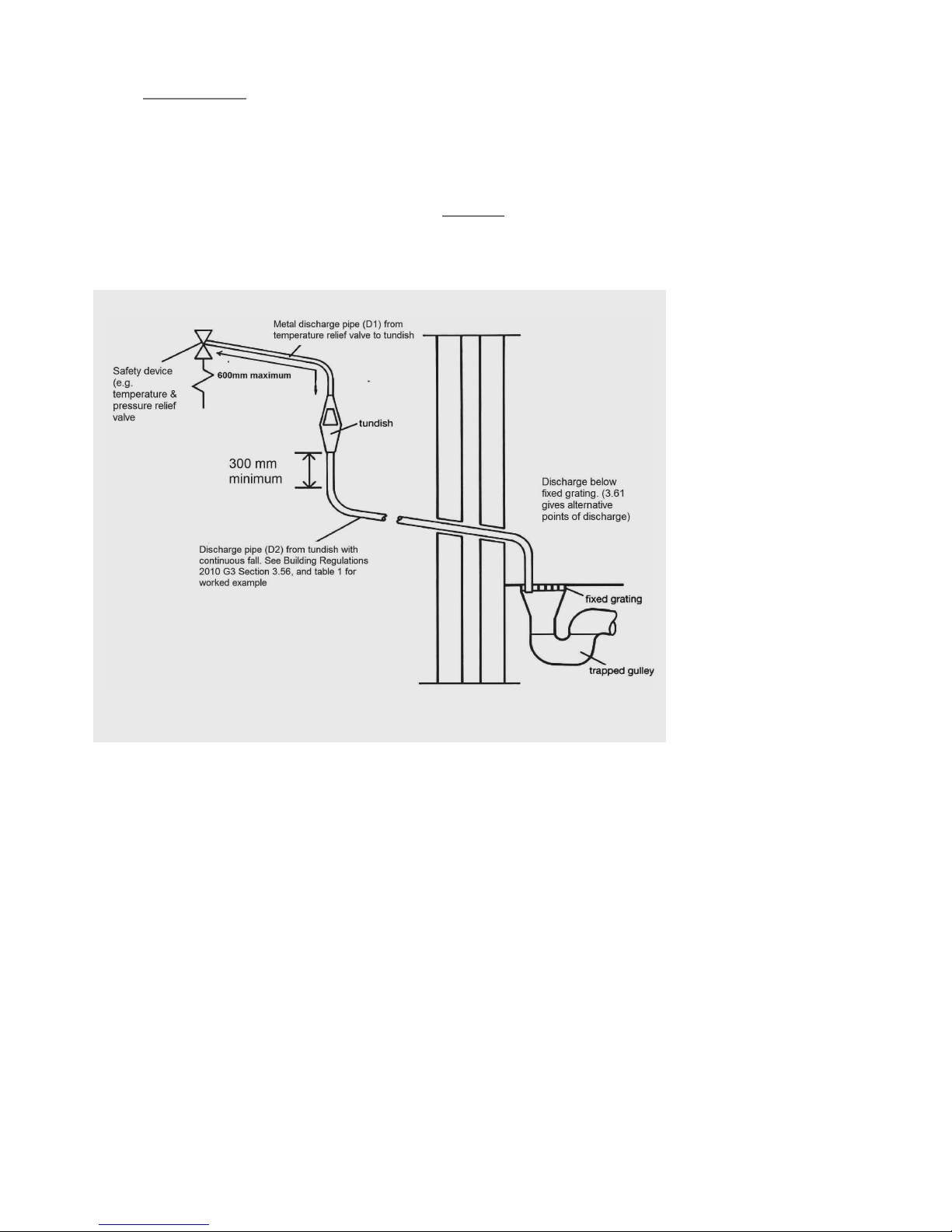
DISCHARGE ARRANGEMENT
Position the inlet control group so that the discharge from both
safety valves can be joined together via a 15mm end feed Tee (see
diagram above). Connect the Tundish and route the discharge
pipe. The discharge pipework must be routed in accordance with
Part G3 of schedule 1 of the Building Regulations. The information
that follows is not exhaustive and if you are in doubt you should
seek advice. The two safety valves will only discharge water under
fault conditions. When operating normally water will not be
discharged. The tundish should be vertical, located in the same
space as the unvented hot water storage system and be tted
as close as possible to, and lower than, the safety device, with
no more than 600mm of pipe between the valve outlet and the
tundish. The tundish should be positioned away from electrical
devices.
Any Discharge should be visible at the tundish. The tundish should
be located such that any discharge is visible. In addition, where
discharges from safety devices may not be apparent, e.g. people
with impaired vision or mobility, consideration should be given to
the installation of a suitable safety device to warn when discharge
takes place, e.g. electronically operated.
Diagram of a typical discharge pipe arrangement (extract from
Building Regulation G3)
Note: The discharge will consist
of scalding water and steam.
Asphalt, roong felt and
non-metallic rainwater goods
may be damaged by such
discharges.
Note: D2 pipe from tundish is
now allowed to be installed in
soil stacks within premises. This
activity is not recommended
by Kingspan as discharge
from T&P may continue for
long periods of time. It is the
installer’s responsibility to
ensure the discharge pipework
can support the discharge for
prolonged periods.
If used follow guidance on
mechanical seal without water
trap given in G3 Building
Regulations.
As discharge can be in
excess of 90oC discharge into
plastic pipework is also not
recommended.

08
EVERFLO STAINLESS UV
UNVENTED HOT WATER CYLINDERS
The discharge pipe (D2) from the tundish should:
A) Have a vertical section of pipe at least 300mm long, below the
tundish before any elbows or bends in the pipework.
B) Be installed with a continuous fall of at least 1 in 200 thereafter.
The discharge pipe (D2) from the tundish should be of metal or
other material that have been demonstrated to be capable of
withstanding temperatures of the water discharged.
The discharge pipe (D2) should be at least one pipe size larger
than the nominal outlet size of the safety device unless its total
equivalent hydraulic resistance exceeds that of a straight pipe
9m long i.e. discharge pipes between 9m and 18m equivalent
resistance length should be at least two sizes larger than the
nominal outlet size of the safety device, between 18 and 27m at
least 3 sizes larger, and so on. Bends must be taken into account
in calculating the ow resistance. Refer to diagram 1, Table 1 and
the worked example. An alternative approach for sizing discharge
pipes would be to follow BS6700 Specication for design
installation, testing and maintenance of services supplying water
for domestic use within buildings and their curtilages.
The discharge pipe (D2) should terminate in a safe place where
there is no risk to persons in the vicinity of the discharge.
Examples of acceptable discharge arrangements are:
a. To a trapped gully with the end of the pipe below the xed
grating and above the water seal.
b. Downward discharges at a low level; i.e. up to 100mm above
external surfaces such as car parks, hard standings, grassed
areas etc. are acceptable providing that where children play or
otherwise come into contact with discharges, a wire cage or
similar guard is positioned to prevent contact whilst maintaining
visibility.
c. Discharges at a high level; e.g. in to metal hopper and metal
down pipe with the end of the discharge pipe clearly visible or
onto a roof capable of withstanding high temperature discharges
of water and 3m from any plastic guttering systems that would
collect such discharges.
d. Device to warn when discharge takes place.
WORKED EXAMPLE
The example below is for G1/2 temperature relief valve with a
discharge pipe (D2) having 4 No. elbows and length of 7m from
the tundish to the point of discharge.
From Table 1:
Maximum resistance allowed for a straight length of 22mm
copper discharge pipe (D2) from a G1/2 temperature relief valve is:
9.0m. Subtract the resistance for 4 No. 22mm elbows at 0.8m each
= 3.2m. Therefore the maximum permitted length equates to:
5.8m. 5.8m is less than the actual length of 7m therefore calculate
the next largest size. Maximum resistance allowed for a straight
length of 28mm pipe (D2) from a G1/2 temperature relief valve
equates to: 14m. As the actual length is 7m, a 28mm (D2) copper
pipe will be satisfactory.
TABLE 1
Sizing of copper discharge pipe ‘D2’ for a temperature
relief valve with a G1/2 outlet size (as supplied).
Size of
discharge
pipework
Maximum length of
straight pipe
(no bends or elbows)
Deduct the gure below
from the maximum length
for each bend or elbow in the
discharge pipe
22mm Up to 9m 0.8m
28mm Up to 18m 1m
35mm Up to 27m 1.4m

09 EVERFLO STAINLESS UV
UNVENTED HOT WATER CYLINDERS
EVERFLO STAINLESS UV
SLIMLINE DIRECT
EVERFLO STAINLESS UV
SLIMLINE INDIRECT
25.0˚
40.0˚
45.0˚
35.0˚
15.0˚
40.0˚
45.0˚
15.0˚
B
A
120.00
“ F PTRV BOSS
1
2
D A B C G
F D A B C G
22mm HOT
DRAW - OFF
22mm SECONDARY
RETURN (not always tted.
See table)
22mm COLD FEED WITH
DIP PIPE TO DEFLECTOR
IN BOTTOM OF CYLINDER
22mm HOT
DRAW - OFF
22mm SECONDARY
RETURN (not always tted.
See table)
“ F PTRV BOSS
1
2
22mm COLD FEED WITH
DRY STAT POCKET
DIP PIPE TO DEFLECTOR
IN BOTTOM OF CYLINDER
120.00
SECOND IMMERSION HEATER
(not always tted. See table)
30.0˚
50.0˚ 50.0˚
10.0˚
25.0˚
40.0˚
45.0˚
35.0˚
15.0˚
40.0˚
45.0˚
15.0˚
B
A
120.00
“ F PTRV BOSS
1
2
D A B C G F D A B C G
22mm HOT
DRAW - OFF
22mm SECONDARY
RETURN (not always tted.
See table)
22mm COLD FEED WITH
DIP PIPE TO DEFLECTOR
IN BOTTOM OF CYLINDER
22mm HOT
DRAW - OFF
22mm SECONDARY
RETURN (not always tted.
See table)
“ F PTRV BOSS
1
2
22mm COLD FEED WITH
DRY STAT POCKET
DIP PIPE TO DEFLECTOR
IN BOTTOM OF CYLINDER
120.00
SECOND IMMERSION HEATER
(not always tted. See table)
30.0˚
50.0˚
50.0˚
10.0˚
CODE HEIGHT DIAMETER A B C D G
EDS60 673 478 175 210 N/F N/F 483
EDS90 1048 478 175 210 610 N/F 858
EDS120 1236 478 175 210 710 N/F 1046
EDS150 1424 478 175 210 810 N/F 1234
EDS180 1674 478 175 210 910 N/F 1484
EDS210 1987 478 175 210 1100 1500 1797
25.0˚
40.0˚
45.0˚
35.0˚
15.0˚
40.0˚
45.0˚
15.0˚
B
A
120.00
“ F PTRV BOSS
1
2
D A B C G
F D A B C G
22mm HOT
DRAW - OFF
22mm SECONDARY
RETURN (not always tted.
See table)
22mm COLD FEED WITH
DIP PIPE TO DEFLECTOR
IN BOTTOM OF CYLINDER
22mm HOT
DRAW - OFF
22mm SECONDARY
RETURN (not always tted.
See table)
“ F PTRV BOSS
1
2
22mm COLD FEED WITH
DRY STAT POCKET
DIP PIPE TO DEFLECTOR
IN BOTTOM OF CYLINDER
120.00
SECOND IMMERSION HEATER
(not always tted. See table)
30.0˚
50.0˚ 50.0˚
10.0˚
CODE HEIGHT DIAMETER A B C D F G
ENS60 673 478 340 380 440 395 N/F 483
ENS90 1048 478 340 380 440 395 N/F 858
ENS120 1236 478 340 380 440 395 N/F 1046
ENS150 1424 478 380 420 520 520 N/F 1234
ENS180 1674 478 380 420 520 610 N/F 1484
ENS210 1987 478 380 420 520 710 1500 1797
TECHNICAL SPECIFICATIONS

10
EVERFLO STAINLESS UV
UNVENTED HOT WATER CYLINDERS
EVERFLO STAINLESS UV DIRECT
EVERFLO STAINLESS UV INDIRECT
25.0˚
40.0˚
45.0˚
35.0˚
15.0˚
40.0˚
45.0˚
15.0˚
B
A
120.00
“ F PTRV BOSS
1
2
D A B C G F D A B C G
22mm HOT
DRAW - OFF
22mm SECONDARY
RETURN (not always tted.
See table)
22mm COLD FEED WITH
DIP PIPE TO DEFLECTOR
IN BOTTOM OF CYLINDER
22mm HOT
DRAW - OFF
22mm SECONDARY
RETURN (not always tted.
See table)
“ F PTRV BOSS
1
2
22mm COLD FEED WITH
DRY STAT POCKET
DIP PIPE TO DEFLECTOR
IN BOTTOM OF CYLINDER
120.00
SECOND IMMERSION HEATER
(not always tted. See table)
30.0˚
50.0˚
50.0˚
10.0˚
15.0 0
25.0 0
30.0 0
45.0 0
160mm
195mm
FD
22mm HOT
DRAW - OFF
“ F PTRV BOSS
22mm SECONDARY
RETURN (not always tted.
See table)
22mm COLD FEED WITH
DIP PIPE TO DEFLECTOR
IN BOTTOM OF CYLINDER
1
2
SECOND IMMERSION
HEATER (not always tted.
See table)
CODE HEIGHT DIAMETER D F
ED90 718 550 N/F N/F
ED120 906 550 N/F 510
ED150 1093 550 N/F 610
ED180 1281 550 N/F 710
ED210 1469 550 1000 810
ED250 1719 550 1250 950
ED300 2032 550 1500 1100
22mm COLD FEED WITH
DIP PIPE TO DEFLECTOR
IN BOTTOM OF CYLINDER
22mm SECONDARY
RETURN (not always tted.
See table)
22mm HOT
DRAW - OFF
“ F PTRV BOSS
1
2
DRY STAT
POCKET
SECOND IMMERSION HEATER
(not always tted. See table)
F E D C B A
40.0 0
45.0 0
15.0 0
25.0 0
35.0 0
50.0 0
10.0 0
CODE HEIGHT DIAMETER A B C D E F
EN90 718 550 290 330 390 345 N/F N/F
EN120 906 550 290 330 390 345 N/F N/F
EN150 1093 550 330 370 465 385 N/F N/F
EN180 1281 550 330 370 465 385 N/F N/F
EN210 1469 550 365 405 465 465 N/F 1150
EN250 1719 550 365 405 465 560 950 1400
EN300 2032 550 365 405 465 660 1100 1600
All Dimensions are in mm and
are of the cased unit.
N/F = not tted.
TECHNICAL SPECIFICATIONS

11 EVERFLO STAINLESS UV
UNVENTED HOT WATER CYLINDERS
TECHNICAL SPECIFICATIONS
EVERFLO STAINLESS UV
SOLAR DIRECT
AB GCDEF
22mm HOT DRAW-OFF
22mm COLD FEED
WITH DIP PIPE
TO DEFLECTOR
IN BOTTOM
OF CYLINDER
“
F PTRV BOSS
1
2
DRY STAT
POCKET
25.0015.00
40.0045.00
35.00
22mm SECONDARY
RETURN (not always fitted.
See table)
AB GCDEF
22mm HOT DRAW-OFF
22mm COLD FEED
WITH DIP PIPE
TO DEFLECTOR
IN BOTTOM
OF CYLINDER
“
F PTRV BOSS
1
2
DRY STAT
POCKET
25.0015.00
40.0045.00
35.00
22mm SECONDARY
RETURN (not always fitted.
See table)
CODE HEIGHT DIAMETER A B C D E F G
ESD150 1093 550 290 345 390 610 N/F 892 390
ESD180 1281 550 290 345 445 710 N/F 1080 390
ESD210 1469 550 365 420 500 810 1150 1268 465
ESD250 1719 550 365 420 670 1045 1400 1519 465
ESD300 2032 550 365 420 670 1100 1600 1831 465

12
EVERFLO STAINLESS UV
UNVENTED HOT WATER CYLINDERS
TECHNICAL SPECIFICATIONS
EVERFLO STAINLESS UV
SOLAR INDIRECT
All Dimensions are in mm and
are of the cased unit.
N/F = not tted.
25.0 015.0 0
40.0 045.0 0
35.0 0
DRY STAT
POCKET
DRY STAT
POCKET
22mm COLD
FEED WITH DIP PIPE
TO DEFLECTOR IN
BOTTOM OF CYLINDER
22mm SECONDARY RETURN
(not always tted. See table)
½” F PTRV BOSS
22mm HOT DRAW-OFF
EF D C B A G H
50.0 00
45.0
CODE HEIGHT DIAMETER A B C D E F G H
ET150 1093 550 290 345 642 697 N/F 892 390 693
ET180 1281 550 290 345 674 729 N/F 1080 390 725
ET210 1469 550 365 420 779 834 1150 1268 465 830
ET250 1719 550 365 420 950 1005 1400 1518 465 1000
ET300 2032 550 365 420 979 1034 1600 1832 465 1030

13 EVERFLO STAINLESS UV
UNVENTED HOT WATER CYLINDERS
EVERFLO SOLAR
UNVENTED
DIRECT SINGLE COIL CYLINDER
Detail for the installation of a Solar Unvented Direct cylinder.
GENERAL
When installing this product it is essential the overall installation
meets all current legislation including, in particular, the high limit
isolation requirements of Building Regulation G3. This document
is designed to assist in achieving that aim.
WATER
The potable water connection and tundish discharge connection
are to be connected in exactly the manner described in Pages 5 to
8 of this manual.
IMMERSION HEATERS
The standard issue immersion heaters are designed for domestic
usage where the lower heater is connected to a low rate o-peak
tari and the upper heater used for occasional top-up purposes.
Heaters of this nature are not designed to be permanently live.
Connect in accordance with instructions on page 6.
SOLAR CONNECTIONS
The ow and return from the solar heat source are to be
connected to the indirect coil. Either primary coil connection may
be utilised as the ow or return. The solar primary circuit must
have its own dedicated circulating pump, thermal and safety
controls which must be installed as per the solar manufacturers
instructions. The solar control system used must be of the solar
dierential control type and should be connected to the solar
sensor.
The solar sensor, supplied as part of the solar controls should be
inserts into Pocket B (page 11) and is held in-situ with the black
sensor pocket retaining bung provided.
It is necessary to connect the solar pump via the over-temperature
high limit cut-out (provided) to ensure the heat input to the solar
coil is interupted if the cylinder over heats. Some method to
prevent thermosyphoning must also be employed. Non-return
check valves in the primary ow and return pipework would be
acceptable.
If solar controls do not oer appropriate isolation a 2 port zone
valve (not supplied) can be used with the pump and high limit stat
as shown on pages 13 and 14.
INDIRECT TWIN COIL CYLINDER
UPPER COIL
The upper coil is connected to the fossil fuel boiler as per the
instructions for the EVERFLO STAINLESS UV Unvented Indirect
single coil model with the dual stat control and high limit
thermostat inserted into pocket D (diagram page 12). The wiring
requirements are as depicted on page 14.
LOWER COIL: SOLAR INSTALLATION
The ow and return from the solar heat source are to be
connected to the indirect coil. Either primary coil connection may
be utilised as the ow or return. The solar primary circuit must
have its own dedicated circulating pump, thermal and safety
controls which must be installed as per the solar manufacturers
instructions. The solar control system used must be of the solar
dierential control type and should be connected to the solar
sensor.
The solar sensor, supplied as part of the solar controls should
be inserts into Pocket B and is held in-situ with the black sensor
pocket retaining bung provided.
It is necessary to connect the solar pump via the over-temperature
high limit cut-out (provided) to ensure the heat input to the solar
coil is interrupted if the cylinder overheats. Some method to
prevent thermosyphoning must also be employed. Non-return
check valves in the primary ow and return pipework would be
acceptable. If solar controls do not oer appropriate isolation a
2 port zone valve (not supplied) can be used with the pump and
high limit stat as shown on page 14.
NOTE: If it is intended to t a cylinder with a solar coil to be used at
a later date, the 2 coils should be connected in series to make use
of the solar coil, using the dual stat in Pocket D
The Domestic Heating Compliance Guide document L1A and
L1B provides excellent advice in sizing both cylinder designated
solar areas and heat exchangers to the surface area of the solar
collectors. Using this guide Range are able to oer sizing advice
for specication.
NB: The total detail of compliance guide document should be
consulted prior to specifying product or commencing design.
14
EVERFLO STAINLESS UV
UNVENTED HOT WATER CYLINDERS
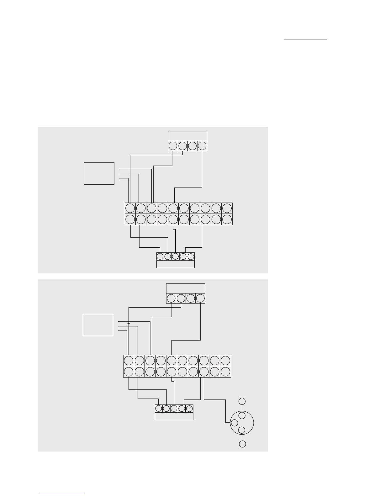
SOLAR HIGH LIMIT CONTROL
These schematic wiring
diagrams depict an IMIT high
limit control stat and the
connections are numbered
accordingly. Where an
alternative is supplied , such as
the solar dierential controller,
connect as per manufacturer’s
instructions.
1 2 3 4 5 6 7 8 9 10
1 2 3 4 5 6 7 8 9 10
B
LG O
B
R
G
Y
ZONE VALVE
L
N
PUMP
E
3
2
E C 1 2
HIGH LIMIT CONTROL
Maints supply
double pole
fused spur
230/220 3amp L
N
E
E C 1 2
HIGH LIMIT CONTROL
Maints supply
double pole
fused spur
230/220 3amp L
N
E
1 2 3 4 5 6 7 8 9 10
1 2 3 4 5 6 7 8 9 10
B
LG O
B
R
G
Y
ZONE VALVE
1 2 3 4 5 6 7 8 9 10
1 2 3 4 5 6 7 8 9 10
B
LG O
B
R
G
Y
ZONE VALVE
L
N
PUMP
E
3
2
E C 1 2
HIGH LIMIT CONTROL
Maints supply
double pole
fused spur
230/220 3amp L
N
E
E C 1 2
HIGH LIMIT CONTROL
Maints supply
double pole
fused spur
230/220 3amp L
N
E
1 2 3 4 5 6 7 8 9 10
1 2 3 4 5 6 7 8 9 10
B
LG O
B
R
G
Y
ZONE VALVE
TYPICAL SCHEMATIC WIRING DIAGRAMS

15 EVERFLO STAINLESS UV
UNVENTED HOT WATER CYLINDERS
TYPICAL SCHEMATIC WIRING DIAGRAMS
The diagrams shown relate to the components listed. Other
components and other manufacturers’ components may vary in
their wiring requirements, particularly thermostats. Always refer
to manufacturers’ instructions which may override the detail in
order to function correctly.
VARIANT DUAL THERMOSTAT WIRING
WIRING DIAGRAM 2 x TWO PORT ZONE VALVES (S-PLAN)
WIRING DIAGRAM 2 PORT ZONE VALVE (S-PLAN)
VARIANT DUAL THERMOSTAT WIRING
2 PORT (HTG)
Br G BI O G
Y
123 3
2
1
DUAL STAT 2 PORT (DHW)
C2 C 21Br G Bl O G
Y
1 2 3 4 5 6 7 8 9 10
1 2 3 4 5 6 7 8 9 10
WIRING CENTRE
3
L
N
2
L N
1 2 3 4 L N E 4 5 6 1 2 3 4
2
5A SUPPLY
ROOM STAT PROGRAMMER BOILER
PUMP

16
EVERFLO STAINLESS UV
UNVENTED HOT WATER CYLINDERS
TYPICAL SCHEMATIC WIRING DIAGRAMS
WIRING DIAGRAM THREE PORT MID POSITION VALVE (Y-PLAN) +
TWO PORT VALVE
VARIANT DUAL THERMOSTAT WIRING
WIRING DIAGRAM 3 PORT MID POSITION (Y-PLAN) +2 PORT VALVE
WIRING DIAGRAM 3 PORT MID POSITION (Y-PLAN) + 2 PORT VALVE
VARIANT DUAL THERMOSTAT WIRING
3 PORT (HTG)
WG BI O G
Y
723 3
2
1
DUAL STAT 2 PORT (DHW)
C2 C 21Br G Bl O G
Y
1 2 3 4 5 6 7 8 9 10
1 2 3 4 5 6 7 8 9 10
WIRING CENTRE
3
L
N
2
L N
1 2 3 4 L N E 4 5 6 1 2 3 4
2
5A SUPPLY
ROOM STAT PROGRAMMER BOILER
PUMP

17 EVERFLO STAINLESS UV
UNVENTED HOT WATER CYLINDERS
SINGLE ZONE HEATING
TWIN ZONE HEATING
Connect power supply as per instruction manual. TP9000 terminals 5 & 6 can be used for remote sensor connection.
Connect power supply as per instruction manual. TP9000 terminals 5 & 6 can be used for remote sensor connection.
TYPICAL SCHEMATIC WIRING DIAGRAMS
PLUMBED CYLINDER

18
EVERFLO STAINLESS UV
UNVENTED HOT WATER CYLINDERS
CONNECTED TO BOILER WITH PUMP OVER-RUN FACILITY
E N L 1 2 3
TP5000
E N L 3 4 5
TP9000
0W Y G/Y
Green Plug
B1 G/Y
Br
L N E SLB LP
Boilder with over run
BL BR GR OR
Red Plug - Heating 1
BL BR GR OR
Yellow Plug - Heating 2
B1 Br Gr Or
Blue Plug - Water
Wiring Diagram for Twin Zone Heating and Hot Water
TP9000 + TP5000 to system using boilder to control pump
1 2 3 4 5 6 7 8 9 10 11 12
Pump
INSTRUCTION FOR CONNECTION TO A BOILER WITH PUMP OVER
RUN FACILITY SUCH AS IDEAL LOGIC HEAT
1.Disconnect brown pre-wire pump ex from position 10
2.Reconnect brown pre-wire pump ex to position 12
3.Connect 5 core cable between boiler and wiring control centre
to following positions
WIRING CENTRE BOILER
TERMINAL 1 PERMANENT LIVE L
TERMINAL 3 PERMANENT NEUTRAL N
TERMINAL 5 PERMANENT EARTH E
TERMINAL 10 SWITCHED LIVE TO BOILER SL B
TERMINAL 12 SWITCH LIVE TO PUMP L P

19 EVERFLO STAINLESS UV
UNVENTED HOT WATER CYLINDERS
PRE-PLUMBED
CYLINDER INSTALLATION
COLD MAINS PIPEWORK
Run the cold main through the building to the place where the
EVERFLO STAINLESS UV PRE-PLUMB unit is to be installed. Take
care not to run the cold pipe near hot water or heating pipework
so that the heat pick-up is minimized. Identify the cold water
supply pipe and t an isolating valve (not supplied). A 22mm
BS1010 stopcock can typically be used but a 22mm quarter turn
full bore valve would be better as it does not restrict the ow as
much. Do not use “screwdriver slot” or similar valves. Make the
connection to the inlet control set (Position 2). Ensure that the
arrow points in the direction of the water ow. Select a suitable
position for the expansion vessel. Mount it to the wall using the
bracket provided. Connect the expansion vessel to the cold feed
pipework between the inlet control set and the cold inlet. Ensure
that the top of the vessel is accessible for servicing.
CONNECTING TO THE CYLINDER
All of the pipework connections on the cylinder are 22mm
compression and supplied complete with gland nuts and olives, in
the Accessory Kit box. Only connect 22mm Table X copper tube to
these connections. Cut the tube with a pipe cutter and ensure no
sharp edges or burrs protrude. Slide both gland nut and olive onto
the tube and push tube fully home into the connection, ensuring
the tube end fully bottoms on the connection recess. Smear the
outer wall of the olive with plumbing paste and tighten gland nut
in the prescribed manner. Upon lling/commissioning, ensure all
connections are completely watertight.
BALANCED COLD CONNECTION
If there are to be showers, bidets or monobloc taps in the
installation then a balanced cold supply is necessary. There is a
22mm balanced connection on the inlet set.
HOT WATER PIPEWORK
Connect to HWDO (Position 1 on diagram). Run the rst part of the
hot water distribution pipework in 22mm. This can be reduced to
15mm and 10mm as appropriate for the type of tap etc. Your aim
should be to reduce the volume of the hot draw-o pipework to
a practical minimum so that the time taken for the hot water is as
quick as possible. Where monobloc mixing taps and showers are
used, these should be installed to comply with the Water Supply
(Water Fittings) Regulations 1999. If these devices are supplied
with un-balanced supplies there should be single check valves
installed at both inlets, to stop over pressurising of either supply.
CONNECTIONS FOR INDIRECT UNITS
Connect to the boiler ow and return (Positions 19 & 14) lines.
An additional expansion vessel and safety valve is supplied. The
boiler may be Gas, Electric or Oil but must be under eective
thermostatic control. Uncontrolled heat sources such as some
AGA’s, back boilers, solid fuel stoves, etc. are NOT SUITABLE.
Please contact our Technical department for guidance. Connect
to (Position 9 & 13) for the radiator circuits. Twin zone heating unit
are supplied with 2 port zone valves in positions 9a and 9b.
CONNECTIONS FOR SOLAR COILS
Connect to the solar coil as detailed on page 13 ensure the solar
pump is connected via the over temperature cut out as described
on page 13.
SECONDARY CIRCULATION
EVERFLO cylinder can be used with secondary circulation. An
appropriate WRAS approved bronze circulator should be used in
conjunction with a non-return valve to prevent backow. On large
secondary circulation systems it may be necessary to incorporate
an extra expansion vessel into the circuit to accommodate the
increased system water volume. A secondary return boss is tted
as standard on 210, 250 & 300 ltr units (Position 17). On smaller
sizes, tee into the cold feed pipe above the drain.
IMMERSION HEATERS
Only immersion heaters with a thermal cutout may be used. To
help ensure this, the immersion heaters have a special 1¾” thread.
They are rated at 3 kW at 240 V and are of a low noise Incoloy
construction. They have both a thermostat and a high limit cutout.
Please order the correct replacement via ourselves; tting non-
approved immersions may aect your guarantee. When tting,
ensure the ‘O’ ring is positioned correctly on the head of the
immersion heater and lubricate before tting. Fit it by hand until
almost home then tighten gently as the ‘O’ rings will seal easily.
The electrical supply to each immersion heater must be fused at
13A via a double pole isolating switch to BS 3456. The cable must
be 2.5mm2 heat resistant (85°C HOFR) sheathed ex complying
to BS 6141:1981 Table 8. Do not operate the immersion heater/s
until the unit is full of water. Do not operate the immersion
heater/s if any sterilisation liquid is in the cylinder as this will cause
premature failure.
ELECTRICAL CONNECTIONS
Complete the wiring – use the appropriate wiring diagrams on
pages 17 & 18.
COMMISSIONING
Carry out commissioning as per instructions on page 21 and in line
with boiler manufacturer’s instructions for the heating and the
primary circuit. Primary pipework must be lled, bled and tested
in accordance with the boiler manufacturer’s instructions, to avoid
damage to the circulation pump.
This manual suits for next models
5
Table of contents
Popular Water Dispenser manuals by other brands


Vivreau
Vivreau V3-201 owner's manual

gledhill
gledhill PulsaCoil PCS 120 Design, installation & servicing instructions

Judo
Judo i-soft Installation and operating instructions

Smith Water
Smith Water 700 Owner's manual and installation guide

Whirlpool
Whirlpool W10295370 installation instructions

SMC Networks
SMC Networks HAW7 Operation manual