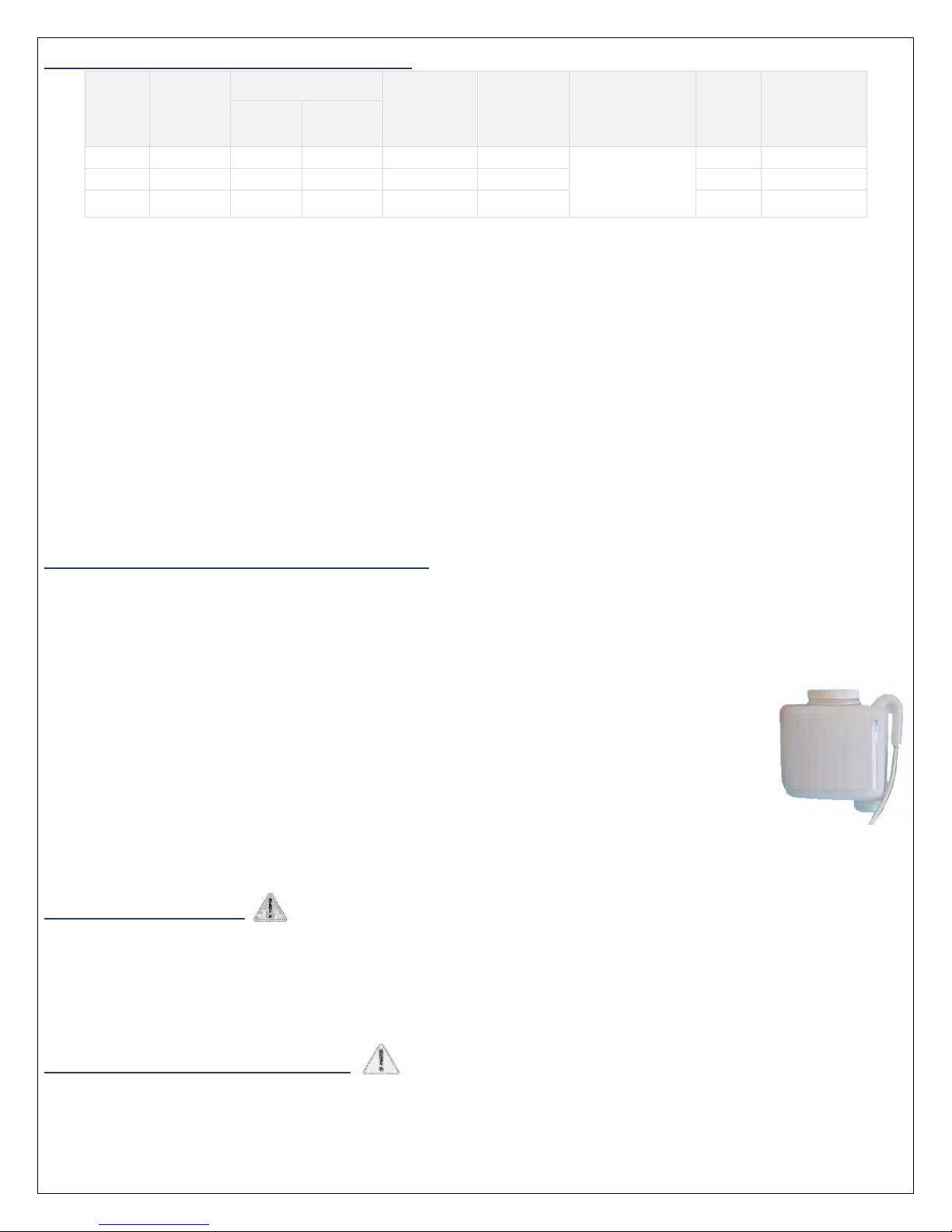
SYSTEM S ECIFICATIONS & DIMENSIONS
Model
System
Capacity
(Grains)
○
Flow Rate ressure Drop
at Rated
Service Flow
(psi)
Media Tank
Size Resin Type
Resin
Volume
(cu ft)
Unit Weight Lbs
(Kg)
Service
(US G M)
Drain (US
G M)
cation
softening resin
The anufacturer reserves the right to ake product i prove ents which ay deviate fro the specifications and descriptions stated herein, without
obligation to change previously anufactured products or to note the change.
Feed Water Quality:
Iron < 5.0 PPM; Manganese < 0.05 PPM ; Turbidity < 1 NTU ; Free Chlorine < 0.5 PPM ; H
2
S – Nil ; Organics – Nil.
If feed water quality exceeds above li its, please call Rainfresh for advice on additional treat ent that ay be necessary.
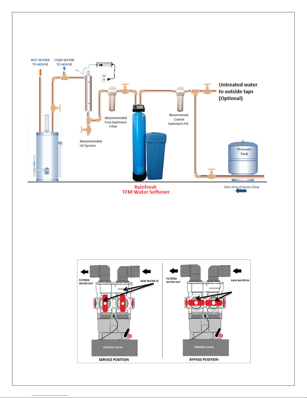
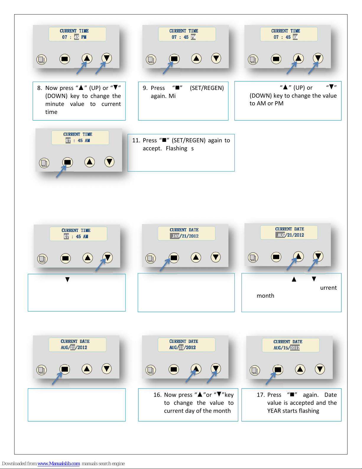
HOW YOUR WATER CONDITIONER WORKS
Your Rainfresh TFM-softener re oves hardness & iron using a process called Ion Exchange. In this process, when water
flows through the unit, hardness-causing inerals such as Calciu & Magnesiu and ferrous iron, are trapped by the edia
(called Resin) and an equivalent a ount of sodiu ions are released into the water. When the capacity of the resin to trap
hardness & iron is exhausted, the unit is re-charged by softener salt in a process called Regeneration. During regeneration,
the unit first backwashes to re ove any sedi ent, rust or other particulates, that ay have
accu ulated in the unit. This is followed by introduction of a saturated salt solution (brine) that bu ps
off the trapped hardness & iron to drain and recharges the resin with sodiu . As iron is hard to
detach fro the resin, the unit includes an auto atic resin-cleaner feeder that installs on the salt tank
and slowly releases resin-cleaner into the brine, which then helps re ove the trapped iron during
regeneration.
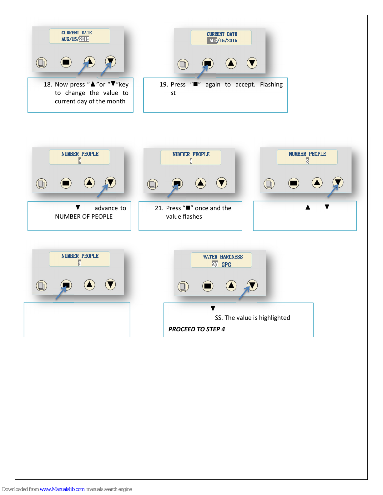
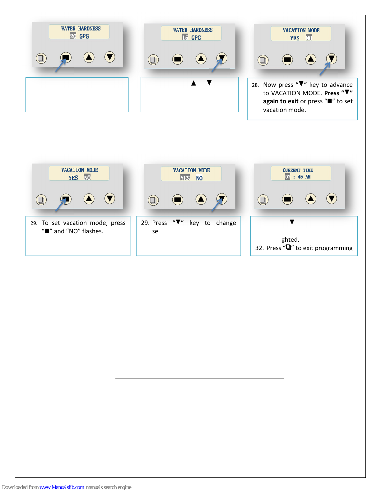
Once you progra the unit at the ti e of installation, the regeneration process happens auto atically.
All you need to do is to ensure that there is always enough salt in the salt tank and resin cleaner in the feeder.
SAFETY RECAUTIONS
-Follow all applicable province/state and local regulations.
-Handle your water softener carefully. Do not lie on side, turn upside down, drop or drag.
-This softener uses salt (sodiu chloride) to regenerate. Persons on sodiu restricted diets should consider the
added sodiu as part of their overall intake. Potassiu chloride can be used as an alternate in such situations.
Please consult Rainfresh technical support.
CAUTIONS BEFORE INSTALLATION
-Install a pressure regulator and water ha er arrestor if pressure exceeds axi u rating at any ti e. Note: If
dayti e pressure is over 80 psi, night ti e pressure ay exceed axi u pressure rating.
@ 15 lbs salt/ft³. Values not supported by test data. Only tested at one salt
setting (Rated Capacity)
•Feed Water Te perature = 4°C - 38°C (39 - 100°F)
•Operating Pressure = 25 (172 kPa) - 100 PSIG (689 kPa)
*
•Voltage = 110 V AC
*
Note: Install pressure regulator and water ha er arrestor if pressure
exceeds rated pressure at any ti e.
At the stated service flow rates, the pressure drop through these
devices will not exceed 15 psig.
•The anufacturer reserves the right to ake product
i prove ents which ay deviate fro the specifications and
descriptions stated herein, without obligation to change
previously anufactured products or to note the change.
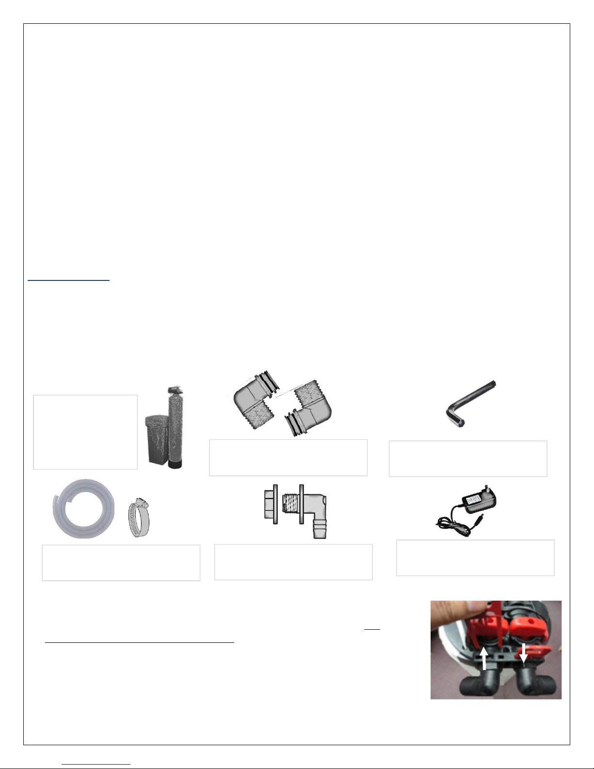
Resin cleaner
feeder