Judo i-soft User manual

Attention:
Carefully read through the instal-
lation and operating instructions
and safety information before
installing and putting the unit into
service.
These must always be issued to
the owner/user.
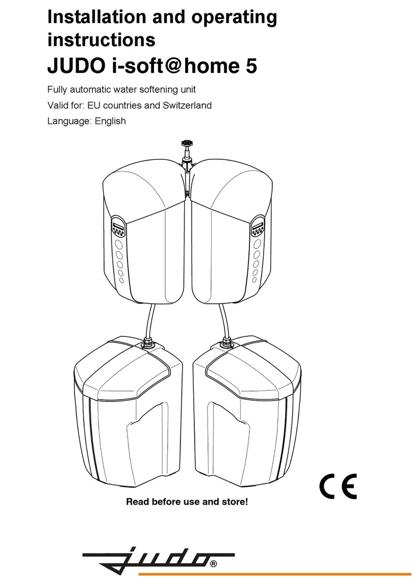
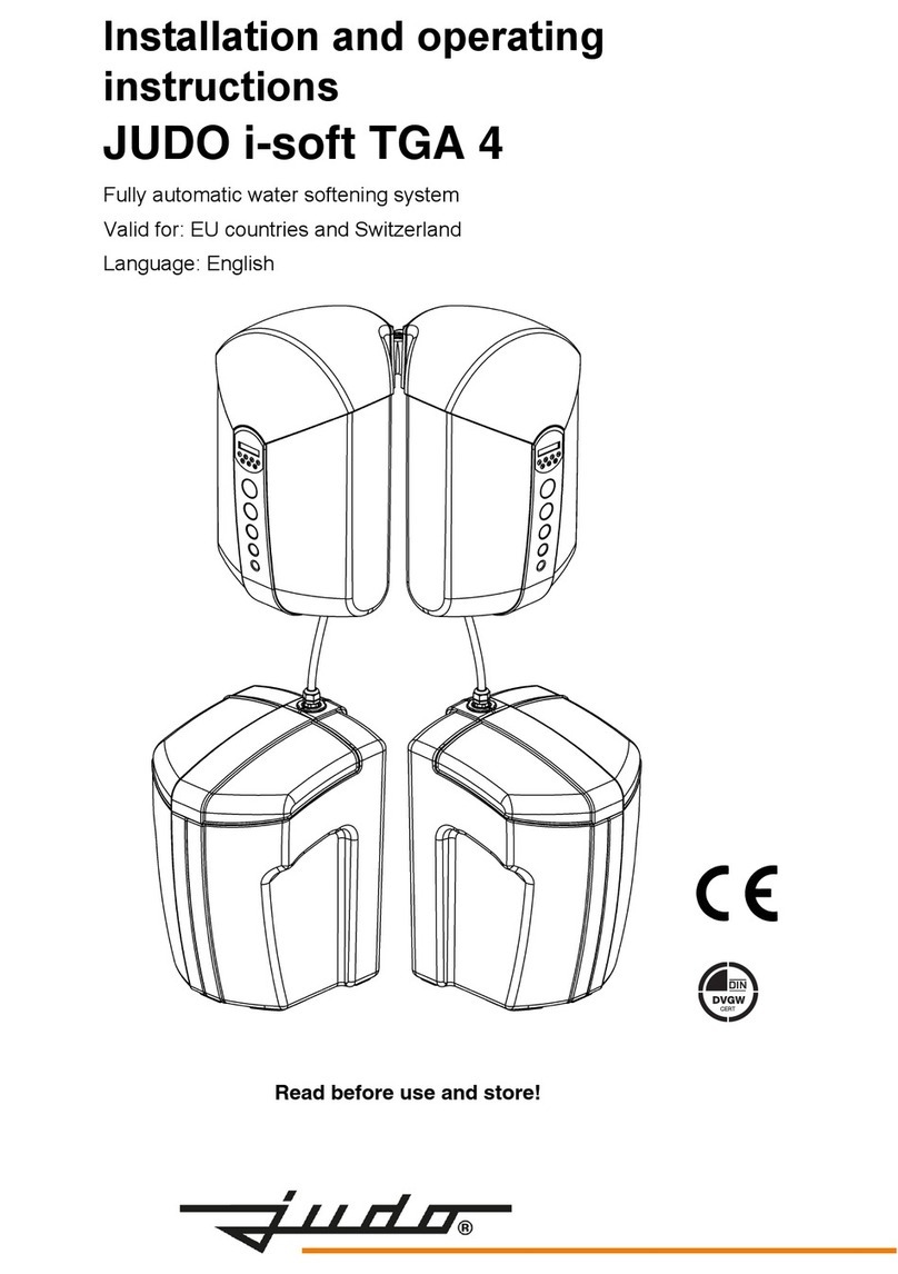
Installation and operating
instructions
JUDO i-soft
Fully automated water softener
Valid for: EU countries and Switzerland
Language: English
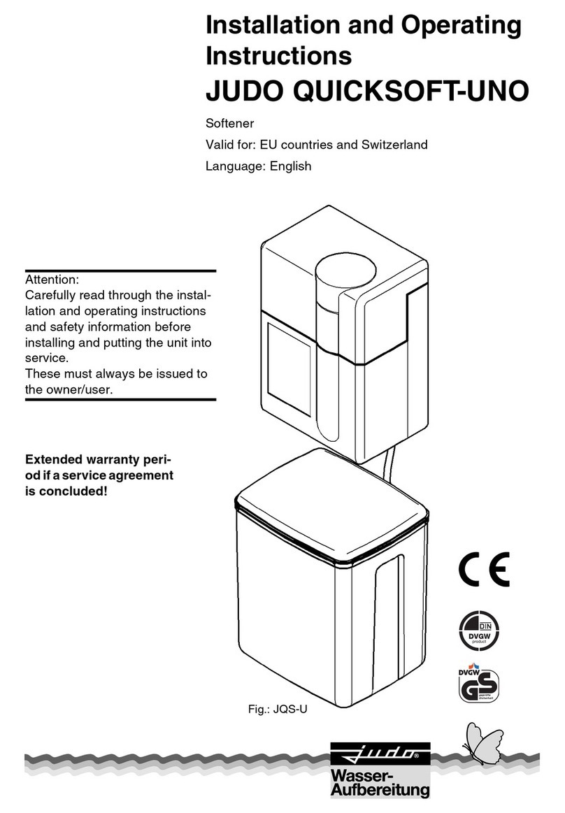
Fig.: i-soft

2 JUDO i-soft
Inquiries, orders, customer support
JUDO Wasseraufbereitung GmbH
P.O. Box 380
71351 Winnenden
Germany
e-mail: info@judo.eu
www.judo.eu
Address
JUDO Wasseraufbereitung GmbH
Hohreuschstraße 39-41
71364 Winnenden
Germany
Trademarks:
Trademarks used in this document are protected
and registered trademarks of the respective
holder.
© JUDO Wasseraufbereitung GmbH
D-71364 Winnenden
All rights reserved.
Reprints – even of extracts – is only permitted
with special approval.
Dear Customer,
thank you for the confidence you have
shown in us by purchasing this unit. With
this softener you have purchased a state
of the art unit.
This softener is suitable for use in cold
drinking water up to a maximum ambient
temperature of 30 °C (86° F).
Each unit is thoroughly checked before
delivery. Should difficulties occur,
please contact your regional customer
service (see back page).

JUDO i-soft 3

4 JUDO i-soft
About these operating instructions
Table of contents
1. About these operating
instructions........................................4
1.1 Symbols used..............................5
1.2 Safety information and dangers
due to non-compliance................5
1.3 Units used....................................5
2. Intended use ......................................6
2.1 Water pressure............................7
2.2 Notes on special dangers............7
3. Product information..........................8
3.1 Intended purpose.........................8
3.2 Mark of conformity.......................8
3.3 Materials used.............................8
4. Installation .........................................8
4.1 General........................................8
4.2 Mounting the softener without a
bypass valve..............................11
4.3 Mounting the bypass valve
(accessories).............................11
4.4 Mounting the softener to the
pre-assembled bypass valve.....12
4.5 Connecting the softener with the
salt container.............................13
4.6 Wastewater connection and
back-up overflow hose...............14
5. Operation .........................................15
5.1 Operational start........................15
5.2 Functional description of the
water softener............................19
5.3 Salt filling...................................19
5.4 Potential-free error message.....20
5.5 Integratingthewatersoftenerintoa
central building control system..21
5.6 Modifications / changes /
spare parts.................................21
5.7 Stoppages .................................21
5.8 Resetting to factory settings......22
5.9 Display message overview........22
6. Faults................................................23
7. Maintenance.....................................24
7.1 Cleaning ....................................24
8. Warranty and services....................24
8.1 Message
“Maintenance / service”.............24
9. Data sheet ........................................ 25
9.1 Type ..........................................25
9.2 Technical specifications ............25
9.3 Diagrams...................................26
9.4 Installation dimensions..............28
9.5 Scope of supply.........................28
9.6 Accessories...............................28
10. Positions i-soft ................................ 30
11. Customer support ........................... 32
1. About these operating
instructions
ATTENTION
(see chapter “Safety information and dan-
gers due to non-compliance”)
The instruction manual must be perma-
nently available at the place in which the
softener is in use.
This instruction manual is intended to make
it easier to familiarize yourself with the
softener and its possible intended uses.
The instruction manual contains important
information concerning the safe, correct and
economical running of this softener.
It contains fundamental information, which
must be observed during installation, opera-
tion and maintenance. Observance of this
information helps to avoid dangers, reduce
repair costs and increase the reliability and
service life of the softener.
The instruction manual must be read and
used by each person entrusted with carrying
out work on the softener, for example:
– installation
– operation
–maintenance
(servicing, inspection, repair)
Installation and maintenance may only be
carried out by personnel authorized by the
manufacturer, capable of fulfilling the
instructions as given in this manual under
consideration of all regulations covering

JUDO i-soft 5
About these operating instructions
plumbing, safety and operation of such units
valid in the country of use.
In addition to the safety regulations as given
in this manual all locally valid regulations
governing accident prevention, all regula-
tions governing health and safety in the
workplace must be observed at all times.
All persons involved in installing, operating
or maintaining this unit must read this
instruction manual before commencing on
any work on or with the unit.
Special attention must be paid addition-
ally to the safety notes embedded into
the main sections of this manual.
1.1 Symbols used
The safety notescontainedin this instruction
manual are labelled with the following
symbols:
Notes directly attached to the built-in roraty
flange or the softener, e.g.
– direction of flow (see fig. 1)
– unit labelling
– cleaning information
must always be observed and kept in a fully
legible condition.
1.2
Safety information and dangers
due to non-compliance
Failure to observe the general danger
symbols can result, for example, in the
following risks:
– failure of important functions of the
softener.
– danger to persons due to electrical and
mechanical effects.
– danger both to persons and the environ-
ment due to leaks.
Refrain from any unsafe methods of work.
Failure to comply with this instruction
manual and the safety information can not
only result in danger to persons but also
prove harmful to the environment and the
unit itself.
1.3 Units used
Varying from the International System of
Units (SI = System International), the follo-
wing units are used:
ATTENTION Notes on
existing
dangers
Warning, electrical voltage
Torques specified by the
manufacturer
Tips for use and other
information
Fig. 1: Built-in rotary flange
Units Conversion
°F °F = 9/5°C + 32
bar 1 bar = 105Pa = 0.1 N/mm²
= 14.5 psi
1" DN 25
°e °e = 0.142 mmol/l
alkaline earth ions

6 JUDO i-soft
Intended use
2. Intended use
Both installation and use of the softener are
subject to all rules and regulations
concerning such units and valid in the
country of use.
In addition to the safety regulations as given
in this manual all locally valid regulations
governing accident prevention, all regula-
tions governing health and safety in the
workplace must be observed at all times.
The water to be softened must conform
to the European drinking water regula-
tions!
Always contact the manufacturer/supplier
before using water of a different quality or
with additives!
This softener is suitable for use in cold
drinking water up to maximum ambient
temperature of 30 °C (86 °F).
It is produced to state of the art standards
and the safety regulations generally
accepted in Germany.
The softener may only be used as described
in the instruction manual. Any other or
further use is deemed not to be intended
use.
Additional dangers exist in case of non-
intended use and where the danger symbols
and safety information are not observed.
The manufacturer/supplier are not liable for
any losses or damage resulting from such
use. The risk is borne solely by the user.
Intended use also includes observing the
instruction manual.
The manufacturer/supplier must always be
consulted before using the softener outside
the use limitations given in the instruction
manual.
The softeners are only to be used in a tech-
nically perfect condition, for their intended
use, safely and in awarenessof the dangers
and with full observance of the instruction
manual!
Have any malfunctions corrected imme-
diately!
In order to be able to safely discharge the
wastewater in operation and in case of any
defect in the system, precise compliance
with the details given in the chapter
“Requirements for the place of installation”
is necessary!
ATTENTION
(see chapter on “Safety information and
dangers due to non-compliance”)
The regenerating salt used is removed from
the softener columns with the wastewater.
Therefore,it may not beused to water plants
or for similar purposes.
The range of use for DVGW-tested
softeners in Germany is specified in the
DIN 1988 standard, part 2, para. 8.3.2.
According to this standard, there are no
restrictions regarding the range of use for
these softeners. This usage specification
may vary in other countries. Please consult
regulations in country of use.
The capacity of the softener is designed so
that it can be used to partially soften all the
water for a detached or multiple use
building, as well as corresponding part water
quantities for hot water, swimming pools,
washing machines and dishwashers.

JUDO i-soft 7
Intended use
2.1 Water pressure
The water pressure must be between 2 bar
(29 psi) and 7 bar (101.5 psi).
The water pressure must not fallbelow 2 bar
(29 psi), as otherwise the function can be
impaired! If the softener is not regularly
regenerated, this can result in a pressure
loss and impairment of the softening function.
ATTENTION
(see chapter “Safety information and
dangers due to non-compliance”)
If the water pressure is over 7 bar (101.5
psi) a pressure reducer must be installed
upstream of the softener (see fig. 2). An
operating pressure of over 7 bar (101.5 psi)
can lead to malfunction and failure.
The optimum operating pressure for the
softener lies between 3 bar (43.5 psi) and
5 bar (72.5 psi). It works most economically
under these pressure conditions.
2.2 Notes on special dangers
2.2.1 Electrical equipment /
installations
Electrical devices / equipment, which are not
splash proof and which are located near the
softener can be damaged by water which
escapes from the softener during regenera-
tion or through improper use. If the electrical
devices / installations are connected to the
power supply, a short circuit can also occur.
In this case there is a risk of people suffering
an electric shock. Electrical devices / equip-
ment located near the softener must there-
fore be splash proof and comply with the
legal regulations for wet rooms (IP44).
ATTENTION
(see chapter “Safety information and dan-
gers due to non-compliance”)
Caution when touching the unit when the
cover is removed! The components in the
electrical circuit can get hot during opera-
tion. Furthermore, moving parts pose a
potential danger.
Potential-free output
Switching voltage................maximal 24 V
Current...................................maximal 1 A
(see chapter “Potential-free error message”)
Fig. 2: Pressure reducer upstream of the unit
For a water pressure of 5 bar
(72.5 psi) to 7 bar (101.5 psi) we
recommend installation of a pres-
sure reducer.
1
1 = Pressure reducer
There must not be any electrical
cables and devices underneath or in
the immediate vicinity of the softener!
The mains voltage is reduced to a
safe, extra-low voltage of 24 V in the
transformer, with which the system’s
electronics are operated. Never use
any other transformer.
Only use low voltage for remote
transmission of error messages via
the potential-free output!

8 JUDO i-soft
Product information
3. Product information
3.1 Intended purpose
This softener is suitable for use in cold
drinking water up to a maximum water
temperature of 30 °C (86 °F).
ATTENTION
(see chapter “Safety information and
dangers due to non-compliance”)
Please refer to the chapter “Intended Use”
for use restrictions.
This softener is used to protect the water
pipes and hot water heater against lime
scale.
Partially softened water protects appliances
and fittings and reduces consumption of
detergents and cleaning agents.
3.2 Mark of conformity
The units conform to the technical regula-
tions for drinking water installations in
accordance with DIN 1988. They are exa-
mined by the DVGW (German Association
for Gas and Water, registered society, tech-
nical scientific association) in accordance
with the requirements of DIN EN 14743 and
DIN 19636-100 for water softening systems
(cation exchangers) in drinking-water instal-
lations and are authorised to bear the
DIN DVGW mark. Regulations and authori-
zation requirements may vary in other coun-
tries,pleaseconsultregulations incountry of
use.
3.3 Materials used
The materials used are resistant to the
physical, chemical and corrosive loads to be
expected in the drinking water and fulfil the
requirements specified in Germany in the
DIN EN 14743 and DIN 19636-100 stand-
ards (“Softeners (cation exchangers) in
drinking water installations”). All materials
are hygienically and physiologically safe.
Plastics fulfil the official guideline of the
German Federal Environmental Agency.
Metallic materials fulfil the requirements in
Germany of the DIN 50930-6 standard
(Impact on the drinking water quality).
4. Installation
4.1 General
ATTENTION
(see chapter “Safety information and
dangers due to non-compliance”)
The unit may only be installed by skilled
personnel.
The chapter “Intended use” must always be
observed!
The pipes must be able to support the
softener safely.
Otherwise mechanical damage or fractures/
bursts can occur in the pipes. This can result
in major water damage. People close to the
softener are exposed to a health risk due to
the large quantities of water released.
Therefore, if necessary, the pipes must be
additionally fixed or supported.
Always observe the given dimensions and
spacings to ensure convenient operation
and servicing (see chapter “Installation
dimensions”).
A clearance of at least 300 mm(11.8 inch) is
required above the softener in order to be
able to
properly carry out all maintenance
and servi
cing work (see chapter “Modifica-
tions / changes / spare parts”).
Lime scale deposits inhibit water
flow and can therefore result in
increased energy consumption.
Fig. 3: DIN DVGW mark

JUDO i-soft 9
Installation
4.1.1 Requirements for the place of
installation
The room where the unit is installed must
be dry and frost-free!
Unauthorised persons must not have
access to the softener!
ATTENTION
(see chapter “Safety information and
dangers due to non-compliance”)
– The ambient temperature must not
exceed 30 °C (86 °F)!
– In order to be able to safely discharge
the wastewater (regeneration) in opera-
tion and in case of any defects that occur
in the system, precise compliance with
the details given in the “Installation”
chapter is necessary!
If the wastewater cannot be safely and
completely discharged, then this may
result in water damage to the house and
installations therein.
– If no bypass valve (JQX) is installed,
there must be a shut-off valve upstream
of the softener! This enables the water
supply to the softener to be interrupted
during installation, servicing/mainte-
nance, repairs and in case of malfunc-
tions.
– The unit can be installed in all standard
drinking water pipes.
– It is not permitted to install the softener
upstream of the water meter!
4.1.2 Installation position
ATTENTION
(see chapter “Safety information and
dangers due to non-compliance”)
Always install the softener in a vertical posi-
tion (± 5°)!
Failure to observe this can impair its function.
4.1.3 Power supply
ATTENTION
(see chapter “Safety information and
dangers due to non-compliance”)
The mains voltage may not be interrupted
(e. g. by light switches). If the power supply
is interrupted during regeneration,
– no regeneration takes place.
– no alarm is given in case of faults.
– water losses or even water damage can
occur.
4.1.4 Mounting the built-in rotary
flange
The built-in rotary flange is used as a
connecting element between the pipe and
the softener.
It is suitable for both horizontal and vertical
pipes.
The installation height depends on the pipe
layout. The minimum installation height from
the floor to the rotary flange is 52 cm (20.5
inch).
The built-in rotary flange must be
installed in flow direction which is
marked by a cast in arrow (see fig. 4).
Failure to comply with this means the
softener cannot work.
ATTENTION
(see chapter “Safety information and
dangers due to non-compliance”)
A power connection (230 V, 50 Hz),
which is permanently live, must be
available.
A splash proof socket is required for
the transformer, in accordance with
the legal regulations for wet rooms.

10 JUDO i-soft
Installation
The flange surface of the built-in rotary
flange must be in a vertical position! The
built-in rotary flange must be fitted so that
mechanical stresses cannot occur! Other-
wise mechanical damage can result in the
built-in rotary flange. Thiscan result in major
water damage.
Therefore, during installation, ensure that no
large forces act on the pipe, built-in rotary
flange and softener.
4.1.5 Mounting the wall support components
The wall support provides the device with safe support and prevents the device from
becoming entangled in tubing. When mounting the wall support (order no. 2201227), please
refer to the corresponding assembly instructions.
The console set (order no. 2201231) mainly serves to secure the unit, and ease the burden
on the tubing.
Fig. 4: Built-in rotary flange
Fig. 5: Wall support components
wall support
console set

JUDO i-soft 11
Installation
4.2 Mounting the softener without
a bypass valve
– Firstly flush the pipe with the newly
installed rotary flange (JQE).
– Then block off the water again (at the
main water tap or blocking valve)
and remove the assembly cover of the
built-in rotary flange.
The connection flange of the softener is
covered by a white protector cap. This pro-
tector cap is secured by two cylinder screws
M6x130 and two threaded bolts M6x137
with nuts.
Prior to removing the protector cap, the two
threaded bolts M6x137 with nuts have to be
removed and replaced with the provided
cylinder screws M6x130.
ATTENTION
Do not grasp into the connection flange
of the device after removing the white
protector cap (danger of high level pres-
sure)!
– Loosen all four cylinder screws M6x130,
but don’t remove them (bayonet fixture)!
– Remove the white protector cap.
The section of the profiled flange gasket
must point towards the built-in rotary flange.
Failure to observe this can lead to leaks and
water escaping.This can in turncause water
damage to the house and its installations.
– Lift up the softener and swivel it through
approx. 30° in an anti-clockwise direction.
– Position it on the built-in rotary flange so
that the screw heads pass through the
bayonet fixing drill holes (see fig. 7 I).
– Swivel the softener through approx. 30°
back in a clockwise direction.
– Tightly fasten the four cylinder screws
M6x130 (see fig. 7 II).
After assembling the softener unscrew the
wall support so far that it rests against the
softener casing and the softener hangs
vertically to the wall.
4.3 Mounting the bypass valve
(accessories)
When assembling a bypass valve between
the built-in rotary flange and and the softe-
ner an additional bypass piping becomes
superfluous to requirements.
– Firstly flush the pipe with the newly
installed rotary flange (JQE).
– Then block off the water again (at the
main water tap or block-off valve) and
remove the assembly cover of the built-
in rotary flange.
– Connect the bypass valve on the flange
side with the cast in letter “R” (pipe
flange) to the built-in rotary flange by
engaging the bayonet fitting (see fig. 8).
Fig. 6: Profiled flange gasket
profiled flange gasket
Select the torque (approx. 4 Nm) so
that the gasket closes and the
softener is not damaged or strained!
Fig. 7: Built-in rotary flange with bayonet fixture
III

12 JUDO i-soft
Installation
– Tightly fasten the four cylinder screws
M6x25.
The hand-wheel of the bypass valve can be
positioned anywhere above the unit or to the
side. Depending on conditions on site,
installation should be carried out ensuring
sufficient access to the hand-wheel.
4.4
Mounting the
softener
to the
pre-assembled bypass valve
The connection flange of the softener is
covered by a white protector cap. This pro-
tector cap is secured by two cylinder screws
M6x130 and two threaded bolts M6x137
with nuts.
Prior to removing the protector cap, the two
threaded bolts M6x137 with nuts have to be
removed and replaced with the provided
cylinder screws M6x130.
ATTENTION
Do not grasp into the connection flange
of the device after removing the white
protector cap (danger of high level pres-
sure)!
– Loosen all four cylinder screws M6x130,
but don’t remove them (bayonet fixture)!
– Remove the white protector cap.
The section of the profiled flange gasket
must point towards the bypass valve. Failure
to observe this can lead to leaks and water
escaping. This can in turn cause water
damage to the house and its installations.
– Lift up the softener and swivel it through
approx. 30° in an anti-clockwise direction.
– Position the softener on the flange of the
bypass valve marked with the cast in
letter “G” (unit flange) so that the screw
heads pass through the bayonet fixing
drill holes.
– Swivel the softener through approx. 30°
back in a clockwise direction.
– Tightly fasten the four cylinder screws
M6x130.
After assembling the softener unscrew the
wall support so far that it rests against the
softener casing and the softener hangs
vertically to the wall.
Select the torque (approx. 4 Nm) so
that the gasket closes!
Fig. 8: Bypass valve
pipe flange ("R")
unit flange ("G")
built-in rotary flange
hand-wheel
Select the torque (approx. 4 Nm) so
that the gasket closes and the
softener is not damaged or strained!

JUDO i-soft 13
Installation
4.5 Connecting the softener with the salt container
1Filling hose (blue)
2Suction hose (black)
3Electrode cable connector
(Avoid any and all contact with water before
connection!)
4Overflow hose
5Wall spacer
The salt container is assembled as
follows (see fig. 9):
1. Push the filling hose (1) (blue) through
the opening in the salt container and
slide it over the connecting piece.
2. Push the suction hose (2) (black)
through the union nut and gasket as far
as it will go and manually tighten it.
3. Push the connector (3a) of the electrode
cable into the cable housing (3b) as far
as it will go.
Place the salt container below the water
softener or next to it on the floor.
4. Slide the overflow hose (4) over the
connecting piece.
5. Screw the wall spacer (5) on approx.
30 mm (1.2 inch).
Fig. 9: Salt container assembly
23a 4
1
3b
5
When doing so, pay attention that
the white marks on the connector
(3a) and the cable housing (3b)
correspond (correct polarity)!
During assembly the connector
and the cable housing may not
come into contact with water!

14 JUDO i-soft
Installation
4.6 Wastewater connection and
back-up overflow hose
The hoses for the regeneration wastewater
and the back-up overflow must both be laid
up to the wastewater sewer without any
kinks. Ensure free discharge above the
wastewater channel or floor drain.
The waste water hosewith 11 mm (0.4 inch)
of outside diameters may not be shifted to a
position higher than the control actuator.
The tube length may amount to maximum
3 m (118 inch). Securely fix the loose end of
the hose to the pipe or similar with the adhe-
sive tape supplied.
The back-up overflow hose with a 19 mm
(0.7 inch) outer diameter must be laid with a
constant fall to the wastewater sewer and
free of kinks.
If the connection for the wastewater sewer is
higher than this, the salt container can be
installed correspondingly higher with the aid
of a wall bracket (see chapter “Accesso-
ries”).
ATTENTION
(see chapter “Safety information and
dangers due to non-compliance”)
An adequately dimensioned wastewater
connection (e. g. floor drain) to DIN 1986, or
local equivalent, must be available for the
wastewater and the back-up overflow hose.

JUDO i-soft 15
Operation
5. Operation
ATTENTION
(see chapter “Safety information and
dangers due to non-compliance”)
Always observe the chapter “Intended use”!
5.1 Operational start
(see fig. 20)
– Optional, to speed up the process: Fill
approx. 5 litres of water into the salt
container (6) until it just covers the inter-
mediate bottom.
– Fill 25-40 kg of regeneration salt into the
salt container (6). The regeneration salt
must comply with the requirements of
DIN EN 973, or local equivalent, and be
of food-grade quality.
We recommend: Broxo or Solvay salt,
or local equivalent, either in blocks or
tablets or in the form of coarse grains
sized 7 - 15 mm. When using other
regeneration salts, clean the salt
container (6) more often and replace the
suction strainer in shorter intervals.
– Remove the cover (7).
– Note down the installation date on the
label (see fig. 12).
– Open the water supply (main water tap
or block-off valve).
– Check if the bypass valve (if installed) is
set to “operation”.
ATTENTION
For safety reasons the softener must be
flushed and regenerated immediately for
venting
after the water
supply is opened.
Ventilation is very simple:
1. Flushing the water softener
– Open a water tap (if possible, near the
water softener) and adjust a volume flow
of approx. 500 l/h.
– After one minute of flushing (resin
container is vented), insert the mains
plug into the mains socket.
After connection to the mains, the electrics
will automatically perform a self-test and a
pre-installation for the regulation operation.
After successful completion, the display will
show the following:
Regulation of residual hardness is pre-confi-
gured to a value of 8 °e.
Please refer to chapter “Setting the residual
hardness” for more information.
2. Starting regeneration of the water
softener with the touch of a button
The water softener has to be in operating
mode. The display shows the operating
mode.
– For manual regeneration start, press the
<OK> key for at least 3 seconds.
Subsequently, the display shows “Rege-
neration”.
Regeneration will be completed after
approx. 20 minutes. Afterwards, the display
again indicates the operating mode.
During system operation, regulation of resi-
dual hardness to the preset value is auto-
matically regulated. To achieve this, approx.
10 litres of water must flow through the
softener.
Fig. 10: Operating mode display
Operating
res. hard. 8 °e

16 JUDO i-soft
Operation
5.1.1
Setting the residual hardness
The residual hardness default of the water
softener is set to 8 °e. To change the resid-
ual hardness setting, press the desired key
(see table) for 3 seconds (this can only be
done when in operating mode). The read-
justed residual hardness is shown in the
second line of the display.
The adjustment of the newly set residual
hardness is automatically performed during
system operation. For this purpose, approx.
10 litres of water must pass through the wa-
ter softener (with approx. 500 l/h flow rate).
Residual hardness can be checked using an
optional hardness measuring equipment
(see chapter “Accessories”).
The test water for checking water hardness
may be taken from the bypass valve or from
any water tap downstream of the water
softener.
Ensure that the readjusted mixed water is
supplied from the water softener to the tap-
ping point.
For a correct comparison of measured
values, the samples should be taken at nor-
mal flow rate (when the tap is fully open).
During sampling, no larger amount of water
may be taken from another tapping point.
5.1.2 Limitations for residual
hardness settings
Residual hardness can only be set to a
maximum of 10 °e.
The water softener control unit checks relia-
bility of the residual hardness settings.
At a maximum, residual hardness must be
about half the value of raw water hardness.
Higher residual hardness can not be
achieved using the blending valve.
If you try to enter higher values via the key-
pad, the display indicates the following:
After 5 seconds, the next possible setup
value is shown (e. g. 8 °e):
This is adopted as the setting value.
The softening increases the sodium concen-
tration in the mixed water, depending on the
raw water hardness and the mixed water
hardness set.
In Germany in accordance with the drinking
water regulations of Jan 1rst 2003 the limit
value for sodium in drinking water is 200 mg/
l. This does not apply to mineral and table
water. Their limit values are considerably
higher, some have values above 1000 mg of
sodium per litre. Values may vary in other
countries, please consult your local regula-
tions.
Fig. 11: Display and foil keypad
Key Residual hardness
11°e
22°e
44°e
66°e
88°e
10 10 °e
Display
Keypad
Input not
possible
M
ax. poss
ibl
e
res. hard. 8 °e

JUDO i-soft 17
Operation
If the calculated overall sodium concentra-
tion exceeds the values permitted by local
the drinking-water regulations, it can be
corrected by increasing residual hardness.
Based on raw water hardness and the resi-
dual water setting, the electronics unit
checks the sodium concentration resulting
from these values. The raw water sodium
concentration will not be considered in the
calculation performed by the electronics
unit. Upon exceeding a limit value stipulated
by local drinking-water regulations, the
display first indicates:
to be followed after 5 seconds with the
message:
After 5 seconds, the admissible minimum
value for residual hardness is shown on the
display. Then the display shows e. g.:
After another 5 seconds, the following comes
up:
By pressing the <OK> key, the admissible
minimum residual hardness value is set. If a
lower residual hardness value is required, it
can be adjusted by pressing keys 1 -10
despite the sodium threshold being excee-
ded.
In case the raw water shows an elevated
sodium concentration it might be necessary
to set residual hardness above 10 °e.
By pressing the <OK> key together with key
<8>, residual hardness can be increased in
steps of 2 °e. Please observe the limitations.
Calculating the sodium content
°e raw water hardness
(askthewaterworksormeasure
with a hardness test device)
- °e mixed water hardness
(measured value)
= °e difference of water hardness
x6.4 mg Na+/l x °e
exchange value for sodium ions
= mg/l increase in sodium content due
to softening
+ mg/l sodium already in the raw water
(ask the waterworks)
= mg/l total sodium content in mixed
water
Tab. 1: Calculating the sodium content
Example calculation of the sodium
content
25 °e raw water hardness
- 10 °e mixed water hardness
= 15 °e difference of water hardness
x 6.4
= 96 mg/l due to softening
+ 10 mg/l from waterworks
= 106 mg/l total
Tab. 2: Example calculation of the sodium content
Attention!
sodium limit val
see instruction
manual
min. possible
res. hard. 10 °e
Accept <OK>
or key 1-10

18 JUDO i-soft
Operation
5.1.3 Recalibrationofresidual
hardness
Due to the difference in the composition of
tap water, the set residual hardness often
cannot be reached. In this case, the regula-
tion of residual hardness can be adapted to
suit the water quality.
For example, if you have set a residual hard-
ness of 6 °e, but the residual hardnessactu-
ally measured 8 °e, the adjustment can be
carried out as follows:
Press key <6> (for desired residual hard-
ness) and shortly afterwards key <8>
(measured residual hardness). The display
shows:
From this information, the control unit deter-
mines the required correction value. The
correction value is shown on the display:
After 5 seconds, the operating mode display
comes up.
The correction can be reset (see chapter
„Resetting to factory setting “).
5.1.4 Country-specific setting
Nom. value 6 °e
Meas. value 8 °e
Correction value
-2 °e
Country DIP switch S5 Unit of hardness Language
Germany Contact 1 ON °dH German
France Contact 2 ON °TH French
Great Britain Contact 3 ON °e Englisch
USA/ Canada Contact 1+2 ON Grains per Gallon Englisch
Belgium Contact 1+3 ON °TH Flemish
Italy Contact 2+3 ON °TH Italian

JUDO i-soft 19
Operation
5.2 Functional description of the
water softener
5.2.1 Mode of operation
The filter container is filled with ion
exchanger resin in the form of small syn-
thetic resin pellets. The calcium ions that are
responsible for water hardness, are ex-
changed for sodium ions here. This makes
water soft. The ion exchanger resin, how-
ever, can only take up a certain quantity of
these hardening components. When the
ability of the resin to take on calcium ions is
exhausted depends on the hardness levels
and general quality of the incoming water
supply. The depletion time is logged by the
water counter, with regeneration being ini-
tiated automatically. In this process, diluted
brine (sodium chloride) is used to remove
the hardening components from the resin.
5.2.2 System concept
The water softener is designed as a parallel
system with regeneration taking place in two
phases. During regeneration, both filter con-
tainers alternate in supplying the system
with soft water. This way, the consumer is
ensured aconstant supply of softened water
even during the regeneration phase.
5.2.3 Regeneration
With a very short regeneration time of a
10 minute interval for each of the two filter
containers, extensive continuous water
removal is still possible.
A water meter is installed in the soft water
line of the system and precisely records the
generated softened water volume and thus
controls the triggering of regeneration. In
accordance with DIN EN 14743 and DIN
19636-100, regeneration is executed with
low amounts of salt. The system is regularly
disinfected to prevent contamination. The
tiny amount of chlorine required for this step
is produced from the drawn-in brine in an
electrolytic process during regeneration.
Regulations in other countries my vary.
Please check your local regulations for
details
5.2.4 Controlling the regeneration
Regeneration is automatically carried out
via wear-free ceramic disc valves. The
regeneration procedure is precisely defined
by the disc geometry, which ensuresthat the
procedure does not have to be re-started
after power failure.
5.2.5 Raw water monitoring
A sensor (i-guard) in the supply side of the
water softener continuously monitors the
raw water intake. This way, the system
knows the amount of water which will start a
regeneration. Programming of raw water
hardness is therefore unnecessary.
5.2.6 Automatic residual hardness
regulation (i-matic)
Depending on the raw water quality and
desired residual hardness, the internal
blending unit is automatically adjusted by
means of a servo motor.
5.2.7 Overflow valve
If the withdrawal of a very large amount of
water (e. g. flush valve) results in a loss of
pressure in the water softening system in
excess of 0.8 bar (11.6 psi), an overflow
valve integrated in the control head opens
up to permit untreated water to pass by the
water softener, thus limiting the loss of pres-
sure. In this process, residual hardness will
temporarily increase in the downstream
softener line.
5.3 Salt filling
The water softener operates automatically.
For each regeneration, approx. 200 g of salt
is used. The regeneration salt has to be
filled up regularly.

20 JUDO i-soft
Operation
5.3.1 Message “Verify salt level”
Usually, regeneration salt is filled up using
25 kg sacks. This amount of salt provides at
least 100 regenerations. After 100 regene-
rations, the display indicates:
After this message, fill up with 25 kg of
regeneration salt. Then press the <OK> key
briefly. This will reset the warning message.
If regeneration salt has already been filled
up before the display indicates it is neces-
sary to do so, the salt quantity regeneration
counter can be reset by pressing <OK>
together with key <1>. The display will then
show the following message:
After 5 seconds, the operating mode comes
up on the display.
5.3.2 Message in case of
insufficient salt
The salt concentration of the brine is
checked duringeach regeneration. If thesalt
container is not topped up in time and the
brine concentration is too low, the display
indicates:
After this message, fill with 25 kg of regener-
ation salt. Then press the <OK> key briefly.
This will reset the warning message.
If salt is only filled up after the salt storage is
completely used up, the brine level might
increase temporarily. In this case, the
suction procedure may take longer.
Our recommendation: Broxo or Solvay
salt, or local equivalent, eitherin blocks, tab-
lets or in the form of coarse grains sized 7 -
15 mm.
ATTENTION
(see chapter “Safety information and dan-
gers due to non-compliance”)
If the regeneration salt is used up or is not
topped up in time, the water softener
switches to economy operation.
In this case, the brine that is still available is
primarily used for disinfecting the ion
exchanger resin and the softening action is
reduced.
This way, the water softener stays in a
thoroughly hygienic condition even for
weeks after the regeneration salt was indi-
cated as being insufficient.
5.4 Potential-free error message
In the following cases a collective error
message can be transferred through the
potential-free relay:
– if there is an error message of the water
softener
– in case of power failure
– in case of insufficient salt
Verify
salt level
Salt reg. counter
reseted
Attention!
Salt deficit
This message might also come
up if the brining procedure cannot
be carried out properly during
regeneration e.g. if the waste
water hose has been installed too
high, if there is insufficient line
pressure or if the suction hose
has not been connected properly
to the salt/brine container.
Table of contents
Other Judo Water Dispenser manuals

Judo
Judo i-soft@home 5 User manual

Judo
Judo QUICKSOFT-UNO User manual

Judo
Judo QUICKSOFT MEGA User manual

Judo
Judo QUICKSOFT-P User manual

Judo
Judo QUICKSOFT MEGA 4 User manual

Judo
Judo QUICKSOFT-UNO User manual

Judo
Judo QUICKSOFT-DUO JQS-D User manual

Judo
Judo JPK 3 User manual

Judo
Judo QUICKSOFT MEGA 6 User manual

Judo
Judo i-soft TGA 4 User manual
Popular Water Dispenser manuals by other brands

Kenmore
Kenmore 625.348600 manual

Follett
Follett 12 Installation, operation and service manual

Soleus Air
Soleus Air WA1-02-21A instruction manual

Electrotemp Technologies
Electrotemp Technologies Estratto 8LCH-KK-SC-SSF user manual

Kenmore
Kenmore 625.38356 owner's manual

Crystal Mountain
Crystal Mountain GLACIER Service manual