EverFocus EverPlex 4BQ User manual

EverPlex 4BQ
USER'S MANUAL
Real time B/W quad processor
High resolution picture quality
4 Alarm input with buzzer

Notice
This manual is presented to the users of EverPlex 4BQ by EverFocus
Electronics Corp. With years of engineering researching, EverFocus has
spared no effort to provide the high quality products to the worldwide users.
For the policy of continual product improvement, EverFocus reserves the right
to make changes to the product specifications and documentation without
notice. All the components of the products, including accessories, components,
and outlook, are based on the agreements if each deals to satisfy all kinds of
users. Meanwhile, please be advised that every steps of operation must follow
the instruction of this manual to keep EverPlex 4BQ working under the best
condition. Please notice that EverFocus will not be charged any claims or
renewing cases resulted from inappropriate operation.

Table of Content
Safety Warning...........................................................................................................1
Introduction................................................................................................................2
Specification...............................................................................................................3
Chapter I Front Panel Keypads.....................................................................4
1. Full Screen.........................................................................................................4
2. Quad Display.....................................................................................................4
3. Sequential Seitching ..........................................................................................4
4. VCR Playback……….. .....................................................................................4
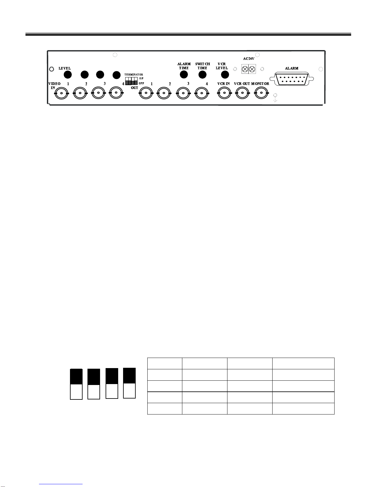
Chapter II Back Panel Function......................................................................5
1. BNC Connectors................................................................................................5
1.1 Video In.........................................................................................................5
1.2 Video Out......................................................................................................5
1.3 Monitor .........................................................................................................5
1.4 VCR out ........................................................................................................5
1.5 VCR In ......................................................................................................5
2. Level .........................................................................................................5
3. Terminator On/off..............................................................................................5
4. Alarm time.........................................................................................................6
5. Switch Time.......................................................................................................6
6. VCR Level.........................................................................................................6
7. Power .........................................................................................................6
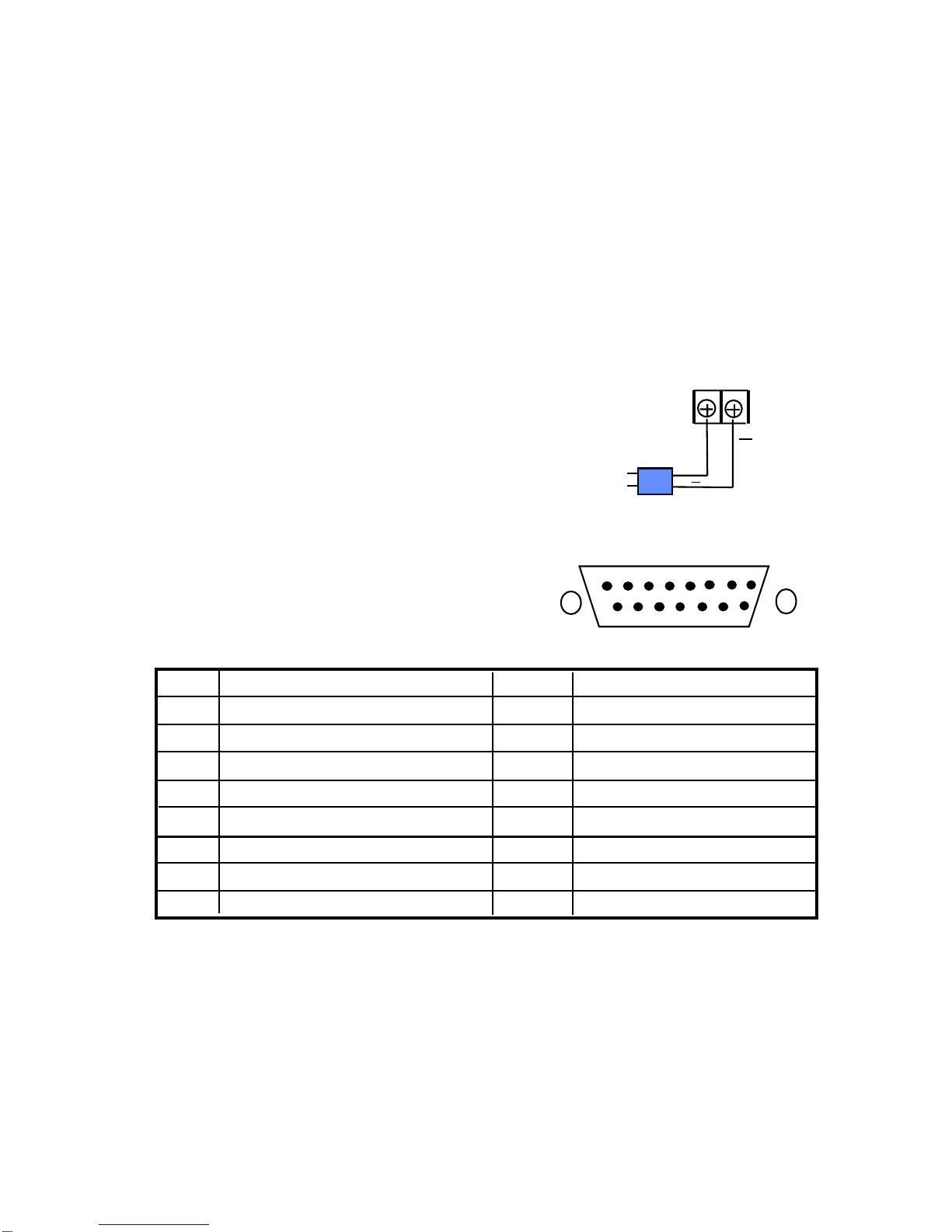
8. Alarm Connectors (DB-15) ...............................................................................6
8.1 Alarm out ......................................................................................................7
8.1.1 Normally Open Connection................................................................7
8.1.2 Normally Closed Connection..............................................................7
8.2 Alarm in ........................................................................................................8

1. To prevent fire or shock hazard, do not expose this equipment to the
environment of high humidity and dust. Do not use it in an unprotected
outdoor installation or any area classified as a wet area.
2. Installation environment: The temperature should be kept between 0oC ~
+50oC
3. For safety sake, do not disseminate the unit or put it on an unstable base.
4. Ventilation: Openings in the enclosure are provided for ventilation and to
ensure reliable operation of the unit and to protect it from overheating. These
openings must not be blocked or covered. This unit should not be placed in a
built-in installation unless proper ventilation is provided.
5. Cleanse: Unplug the unit from the outlet before cleansing. Do not use liquid
cleaners or aerosol cleaners. Use a damp cloth to clean it.
6. Overload: Do not overload outlets and extension cords as this may result in a
risk of fire or electric shock.
7. Power-cord Protection: Power-supply cords should be routed so that they are
not likely to be walked on or pinched by items placed upon or against them,
paying particular attention to cords at plugs, convenience receptacles, and the
point where they exit from the appliance.
8. Object and Liquid Entry: Never push objects of any kind into this unit through
openings as they may touch dangerous voltage points or short-out parts that
could result in a fire or electric shock. Never spill liquid of any kind on the
unit.
9. Service: Do not attempt to service this unit yourself as opening or removing
covers may expose you to dangerous voltage of other hazards. Refer all
servicing to qualified service personnel.
1Safety Warning

2
Introduction
This B/W Quad processor represents the best choice for 4 cameras monitoring
and recording. 4 channel auto sequential switching with real time quad display,
superior high resolution, and the most practical features in one convenient unit.
The most unbeatable B/W Quad processor for the security surveillance.
Connect up to 4 cameras with loop through
Real-time quad display
Option to watch full image or quadrant pictures
Superior high resolution:960 x 576 (CCIR) , 960 x 480 (EIA)
Independent brightness level adjustment for each channel and VCR output
Auto sequential switching for each camera and quad (Dwelling time: 1~10
seconds)
Alarm time setting (1-20 seconds)
4 alarm inputs with built-in buzzer
VCR playback function
Easy-handled desktop size
User-friendly front panel design
Low power consumption
Main Features:

3Specification
Video input: Up to 4 cameras inputs and 1 VCR input
Video output: 1 monitor output and 1 quad output for VCR
1Vp-p/75 ohm
Refresh Rate: 15~30 fields/sec.
VCR Playback: Yes
Alarm input: 4 alarm inputs and 1 alarm reset input
Buzzer: Yes
Alarm output: 2 Alarm Out (1 Normally Open, 1 Normally Closed)
Dimension: 239 x 166 x 55 mm
Power source: AC 24V
Power consumption: 5W max.
Operating temperature: 0°C to +50 °C

4
Chapter I Front Panel Keypads
1. Front Panel Keypads
Seq
1.1 Full Screen
Press any key of corresponding quadrant, the required channel will be displayed as full
screen on the monitor. Press to go back to quad display.
1.2 Quad Display
Press , the 4 camera input will be displayed in quad format on the main monitor.
1.3 Sequential Switching
Press Seq key to enter the auto sequential switching mode. It will display live quad and full
screen sequentially on the main monitor. Press any full screen key or quad display key to
exit Seq mode.
1.4 VCR Playback
Press key to play back the recorded video from VCR. Press any full screen key or quad
display key to exit Seq mode.

5Chapter II Back Panel Function
1. BNC Connectors
1.1 Video In
Connect camera video output to the corresponding video in connector by a 75 ohm
coaxial cable.
1.2 Video Out
Connect the other devices to these connectors. They are used to loop through
camera’s video to other devices.
1.3 Monitor
Connect this output port to the main monitor.
1.4 VCR Out
Connect this output port to the VIDEO IN of VCR. The quad video output is obtained
from this connector.
1.5 VCR In
Connect this input port to the VIDEO OUT of VCR.
2. Level
The 4 gain control regulators is used to adjust the brightness level of the video input.
3. Terminator On/Off
ON
1 2 3 4
Each camera should be terminated by 75 Ohms. This termination is normally
provided by having all switches of 1-4 on. If cameras are looped through to other
equipment which provides termination, then the switch sections of the corresponding
inputs should be turned off.
Terminator Camera Input OFF ON
1 1 Not Terminated 75 Ohm Termination
2 2 Not Terminated 75 Ohm Termination
3 3 Not Terminated 75 Ohm Termination
4 4 Not Terminated 75 Ohm Termination

6
4. Alarm Time
Adjust the alarm holding time from 1 to 20 seconds.
5. Switch Time
Adjust the auto sequential switching time from 1 to 10 seconds.
6. VCR Level
The gain control regulator is used to adjust the brightness level of the VCR output.
7. Power
Connect the AC 24V power source to the power input
terminals. The power supply connection is illustrated
as the right sketch.
AC24V
+
+
AC 24V Adapter
8. Alarm Connectors (DB-15)
PIN # NAME PIN # NAME
1 Alarm Out Common contact 9 Alarm Out Normally Open
2 Alarm Out Normally Closed 10
3 Alarm Reset 11
4 GROUND 12 ALARM IN 1
5 ALARM OUT 13 ALARM IN 2
6 14 ALARM IN 3
7 15 ALARM IN 4
8
1
8
9
15

7
8.1 Alarm out
There are two ways to do the alarm out connection:
8.1.1 Normally Open Connection (use pin # 1 and # 9)
82 1
15 9
COIL
4 Channel B/W Quad
Alarm out
RELAY
8.1.2 Normally Closed Connection (use pin # 1 and # 2)
82 1
15 9
COIL
Alarm out
RELAY
4 Channel B/W Quad

8
8.2 Alarm in
There are 4 alarm sensors in for 4 channels, all these alarm inputs are
Normally Open and shorted to ground means an alarm happens.
82 1
15 9
SENSOR 4
SENSOR 3
SENSOR 2
SENSOR 1
ALARM
CIRCUIT
There are four alarm inputs for each camera. Please connect the alarm input in the same
sequence as the cameras input.
When any alarm signal is input, this quad processor will do the following:
1. switch to the full screen display of the alarmed channel.
2. Light on the channel LED.
3. turn on the buzzer.
When 2 or more alarms occur from the cameras, it will switch to quad display.
When the alarm time is over, it will go back to the normal condition that alarm
occurred before.

EverFocus Electronics Corp.
Head Office:
10F-6, No.79 Sec. 1 Shin-Tai Wu Road,
Hsi-Chi, Taipei, Taiwan
TEL: 886-2-26982334
FAX: 886-2-26982380
USA Office:
145 Vista Ave. Suite 108
Pasadena, CA. 91107
USA
TEL: 1-626-844-8888
FAX: 1-626-844-8838
Toll free: 1-888-383-6287 or
1-888-EV-FOCUS
Hong Kong Office:
Room 0, 10/F., Block 3, Camelpaint Building,
60, Hoi Yuen Road, Kwun Tong, Kowloon
Hong Kong
TEL: 852-2758-9871
FAX: 852-2758-9056
European Office:
Fasanenweg 3, D-46446 Emmerich
Germany
TEL: 49-2822-9394-0
FAX: 49-2822-939495
P/N : M4BQG00100
This manual suits for next models
1
Table of contents
Other EverFocus Media Converter manuals

EverFocus
EverFocus EMX32 User manual

EverFocus
EverFocus EHA-SRX User manual

EverFocus
EverFocus EVS200AW-W User manual

EverFocus
EverFocus EP4CQ FHD User manual

EverFocus
EverFocus EMX32 User manual

EverFocus
EverFocus EVS200A User manual

EverFocus
EverFocus EMX32 User manual

EverFocus
EverFocus EVS410 User manual

EverFocus
EverFocus EHA-CRX User manual