Everidge PrepRite PVS27-6-1 Maintenance manual

1
Tabletop Vacuum Sealing Machine
Operation and Care and
Maintenance Manual
For
PVS27-6-1
PVS32-8-1
PVS32G-8-1
PVS42-12-1
PVS42G-12-2
PVS42GP-12-1
PVS52-25-1
PVS52-25-2
PVS52G-25-2
This appliance is for commercial use only

2
To avoid electrical shock, this appliance MUST be adequately grounded in accordance
with local electrical codes or, in the absence of local codes, with the current edition of
the national Electrical Code ANSI/ NFPA no. 70. In Canada, all electrical connections
are to be made in accordance with CSA C22.1, Canadian Electrical Code Part 1 or local
codes.
Warning!
This appliance is intended for use in commercial establishments where all operators are
familiar with the purpose, limitations, and associated hazards of this appliance.
Operating instructions and warnings must be read and understood by all operators and
users.
1. This appliance must be installed on a stable and level surface.
2. DO NOT install this appliance in any area where it may be affected by any adverse
conditions such as steam, grease, dripping water, high temperatures, etc.
3. DO NOT store or use any flammable liquids or allow flammable vapors in the vicinity
of this appliance or any other appliance.
4. This appliance must be kept free and clear of any combustible materials.
5. This appliance must be kept free and clear of any obstructions blocking access for
maintenance or service.
The sealing bar may reach high temperatures during and after the usage process.
It is recommended to watch out and avoid direct contact until the cooling process
is over.
This machine is designed to be only used indoors

3
These appliances are heavier than they look and should be moved with proper
equipment and personnel.
To reduce the risk of electric shock and injury to persons, unplug from the power
supply before servicing.
This appliance must service by qualified service personnel. Failure to properly
maintain and service to this appliance can and will cause injury or even death.
This appliance has parts that can cause pinching and injury, please ensure that fingers
are kept away from these areas and proper attire is worn.

4
CHAPTER 1
Operation and Care Manual
The operation and care manual is a document
issued by the manufacturing company and is an
integral part of the machine. This document is
adequately identified for easy tracing and/or
subsequent references.
All rights relating to the reproduction and
disclosure of the information contained in this
handbook and the documentation quoted and/or
attached are reserved. This handbook contains
the information necessary for the customer and
assigned personnel, to ensure the correct
installation, use and maintenance of the
appliance allowing it to be used safely.
Safety precautions and
Manufacturer’s liabilities.
Every operations related to the intended use of
this appliance and its overall life cycle has been
carefully and thoroughly analysed by the
manufacturing company during the design
phase, construction phase and the writing of the
operation and care manual.
It is nevertheless understood that experience,
proper training and “common sense” of the
personnel operating this appliance are of the
utmost importance. It is the responsibility of the
operator to observe all safety precautions as
outlined in this manual and to operate this
appliance accordingly.
The non-observance of the safety precautions or
specific warnings indicated in this manual, the
use of this appliance by unauthorized personnel,
violation of all safety standards regarding the
design, construction, and intended use of the
machine, will relieve the manufacturer from all
liability in the case of damage to personnel or
property.
The manufacturing company is therefore in no
way responsible for the non-observance on the
part of the user of the safety precautions listed
in this manual.
Regulatory references
The following manual CONFORMS TO
ANSI/UL Std. 963 –CERT. TO CAN/CSA
Std.C22.2 No. 68 –CONFORMS TO NSF 169
Disposal of this appliance after its
useful life.
Electric and electronic appliances contain
dangerous substances that may have potentially
harmful effects for people and the environment.
It is recommended to dispose of it properly, DO
NOT DISPOSE OF ELECTRICAL OR
ELECTRONIC EQUIPMENT WITH OTHER
MUNICIPAL WASTE.
CHAPTER 2
How to use the Operation and
Care Manual
This document is an integral part of the machine.
Preserve a copy of this operation manual for the
entire working life of the appliance even if
transferred or sold. Additional copies can be
obtained from the manufacturer.
To maintain the operation and care manual in
good condition:
1. Use the operation and care manual carefully
so as to not to damage its contents. In
particular, do not leave the operation and
care manual around after use and return it to
its proper place immediately after
consultation.
2. Do not remove, rip out or rewrite parts of the
operation and care manual. Any changes to
this manual are to be issued by the
manufacturer.
3. Keep the operation and care manual in a safe
place, away from environmental elements
which could damage it.

5
CHAPTER 3
WARRANTY
PrepRite Inc. warrants to the original
purchaser only that any original part that is
found to be defective in material or
workmanship will, at ThermalRite’s option,
subject to provisions hereinafter stated, be
replaced with anew or rebuilt part. For all
other original parts, twelve (12) months from
the date of shipment of appliance. The labor
warranty period is twelve (12) months from
the shipping date. PrepRite will bear
normal labor charges performed during
standard business hours, excluding
overtime, holiday rates or any additional
fees. To be valid, a warranty claim must be
filed during the applicable warranty period.
This warranty is not transferable.
1. All machine components normally
subject to wear and are considered
consumables are not included in the
warranty: Teflon sealing bars, rubber
gaskets , chamber opening pistons,
sealing gaskets ,air filters , oil filters ,
oil changes, pump blades.
2. If the vacuum pump of an appliance
is replaced under warranty because of
aspiration problems, the
manufacturer has the right to inspect
whether any foreign bodies have
been aspirated (liquids, solids,
sauces, etc.). If this is the case, the
repair (part and labor) will not be
covered, since the problem is not due
to manufacturing defects, but to
customer negligence during use.
3. Possible conditions causing electronic
controls to fail include incorrect
electrical supply, environmental
elements, storms, lightning, water
damage, could cause damages which
cannot be attributed to the
manufacturing company and to the
manufacture of the product itself.
4. During the warranty period, for any
defect in workmanship and material,
all parts and labor will be covered. All
warranty claims must be submitted to
and conform by all statements and
policies of the OneSolutionSupport
service.
5. During the warranty period, we will
pay, not to exceed, one (1) hour
travel and fifty (50) miles travel. All
warranty service will be performed by
an authorized service center certified
by the manufacturer. All parts
replaced under warranty must be
returned to the manufacturer for
inspection before any warranty is
paid.
6. Any components considered defective
(pump, electronic control, etc.) and is
determined to be caused by misuse or
abuse during the warranty period
will not be considered under
warranty. The end user will be
responsible for any repairs or parts for
repairs.
7. Equipment modified in any manner
from original model, substitution of
parts other than factory authorized
parts, removal of any parts including
legs, or addition of any parts.
8. Any losses or damage resulting from
malfunction, including loss of product,
food product, revenue, or
consequential or incidental damages
of any kind.
9. Equipment damage caused by
accident, shipping, improper
installation or alteration.
10.This warranty is exclusive and is in
lieu of all other warranties, express or
implied, including the implied
warranties of merchantability and
fitness for a particular purpose. In no
event shall PrepRite be liable for
loss of use, loss of revenue or profit,
or loss of product, or for any indirect,
special, incidental, or consequential
damages. No person except an officer
of PrepRite Inc. is authorized to
modify this warranty or to incur on
behalf of PrepRite any other
obligation or liability in connection
with PrepRite equipment.

6
End User obligations
The end user must immediately inform the
manufacturer of any safety system defect and/or
any malfunction he or she is aware of.
It is strictly forbidden for the end user and/or any
third parties (excluding duly authorized service
personnel of the manufacturer) to make
modifications of any kind to the appliance, its
functions or to this technical publication. In case
of malfunctions or defects due to the non-
observance of the above, the manufacturing
company cannot be held responsible for the
consequences.
CHAPTER 4
GENERAL SAFETY PRECAUTIONS
1. Never touch the metal parts of the machine
with wet or damp hands;
2. Do not pull on the cord to disconnect the plug
from the current outlet.
3. Unqualified or untrained personnel are not
allowed to use the machine without
supervision.
4. Electrical safety of the machine is ensured by
a properly grounded electrical circuit, which
consists of a grounded cord and cord cap and
a correct electrical outlet.
5. The use of an extension cord is not allowed
and may result in injury or death.
6. In the event of damage to the cord, the end
user of the appliance must not attempt to
replace the part. This must be performed by
a qualified service personnel.
7. Always switch off and disconnect the
appliance from the power supply before
beginning any general cleaning or
maintenance operation.
8. Clean appliance coating, panels and controls
using soft and dry cloths, or cloths slightly
soaked in mild detergent solution.
CHAPTER 5
INSTALLATION
Carefully remove the appliance from the carton
or crate. Note: Do not discard the carton and
other packaging material until you have
inspected the unit for hidden damage and tested
it for proper operation.
Location
To ensure proper operation of this appliance and
its components, this appliance must be installed
on a stable and level surface, away from high
humidity items and excessive heat producing
equipment.
DO NOT store or use any flammable liquids
or allow flammable vapors in the vicinity of
this appliance or any other appliance.
DO NOT install this appliance in any area
where it may be affected by any adverse
conditions such as steam, grease, dripping
water, high temperatures, etc.
Disconnect the appliance from power
before performing any service or
maintenance operation which may require
parts.
Before connecting the vacuum packaging
machine, make sure that the voltage
listed on the UL data plate corresponds
with the voltage supplied to the
appliance.
7
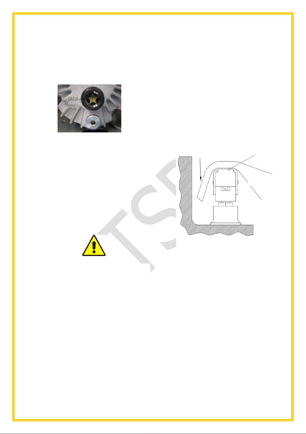
Controls and inspections
Before starting the appliance, check the oil level
through the sight glass located on the
motor/pump.
(Fig. 5.1). In order to access the pump, unscrew
the back panel of the appliance and remove it.
(Fig. 5.1.) Pump oil level indicators
After checking the oil level and ensuring it is level
with the maximum oil level indicator, reinstall the
back panel and secure it with the screws you
removed. Connect the plug to the proper outlet.
If it is not the correct outlet, the outlet must be
replaced with the correct one by a qualified
electrician, as well as ensuring the fuse or
breaker is the correct current capacity for the
draw of the appliance. Do not use adapters,
multiple outlets and/or extension cords.
Do not plug in multiple appliances on the same
outlet that may exceed current capacity of the
outlet.
This appliance must be grounded properly.
If the ground prong is broken, do not use
the appliance until it has been repaired or
serious injury or death may occur.
CHAPTER 6
USING THE VACUUM SEALER
Vacuum packaging
1. Plug in the grounded plug to the correct
outlet.
2. First turn on the main power switch on the
front of the appliance. Next press the
ON/OFF button on the control and the LCD
display should light up.
3. Set the vacuum time (or percentage)
required, the sealing time and the gas
injection time (if the appliance is equipped
with this option.).
4. Position the bag (or bags) with product in
the chamber, the polyethylene shelves can
be used inside the vacuum chamber to level
the product with the sealing bar and position
the bag opening flat on the sealing bar. The
polyethylene shelves can be removed
depending on necessity. (Fig. 6.1).
5. Lower the clear bell-lid and press firmly on it
until it remains closed, thus permitting the
sealing cycle to begin.
6. The different cycle phases are automatic and
after a pre-set amount of time the clear bell-
lid opens thus enabling the product to be
removed and subsequent cycles to begin.
(Fig. 6.1) Correct bag placement in chamber
Vacuum-packaging with inert gas
injection OPTIONAL (ref. table 1)
1. Set the sealing cycle with inert gas injection
on the control panel by pre-selecting the
relative time.
2. Connect the hose coming from the gas
cylinder to the hose connection positioned
on the side/rear of the vacuum sealing
appliance by means of the relevant clamp,
then set the gas cylinder gauge at a
pressure value of 1 ATA.
3. Position the bag containing the product
inside the vacuum chamber, fitting the gas
distribution nozzle inside the bag opening
(Fig. 6.2); make sure that there are no folds
obstructing the gas flow.
Open end of bag
Sealing bag
Cross Section of Chamber
Sealing
Bar

8
(Fig. 6.2) Positioning of the bag with gas
option active.
Vacuum packaging of liquid or
semiliquid products
By using the vacuum sealing appliance of the
correct size, it is possible to vacuum package
liquid or semi-liquid products (soups, sauces,
etc.) thus increasing their shelf life, while
keeping the freshness and taste unaltered.
When doing so, never fill bags up more than
50% of capacity, making sure that the bag
opening is higher than the sealing bar (thus
removing the internal shelves)
1. Vacuum cycles are set as described in the
chapter Vacuum packaging.
2. The SOFT-VACUUM option allows the
packaging of liquid products.
3. All the vacuum packages can be stored in a
freezer or cooler.
Cleaning the appliance
Before cleaning the appliance,
disconnect the power.
During normal usage of the appliance, no
particular cleaning operation of the chamber
machine is required. After the end of each
sealing operation, the chamber should be wiped
out with a damp cloth. Should it be needed (i.e.
bags inner product pours out of the bag), it is
recommended to use a damp cloth and mild
detergent, rinsing thoroughly.
Gas Distribution
Nozzle
Sealing Bag
Cross Section Of Chamber
Sealing
Bar

9
Table 1. EXAMPLES OF PACKAGING WITH INERT GAS INJECTION OPTION
PRODUCT
OXYGEN
% (O2)
CARBON DIOXYDE
% (CO2)
NITROGEN %
(N2)
Sliced salami
-
20
80
Roast meat
80
20
-
Biscuits and oven products
-
100
100
Coffee
-
100
100
Fresh meat
70/80
30/20
-/-
Dehydrated meat and spices
-
-
100
Minced meat
-
-
100
Chocolate
-
100
-
Fresh cheese / Mozzarella
-/-
20/-
80/100
Mature cheese / Cream / Butter /Margarine
-
-
100
Fresh salad / parsley
-
50
50
Yogurt / Puff pastry
-
100
-
Powdered milk
-
30
70
Baking powder
-
100
100
Apples
2
1
97
Sliced bacon
-
35
65
Sandwich loaf / Bread
-
100
-
French toast / Toasted bread
-
80
20
Pasta
-
-
100
Fresh pasta / tortellini / Lasagne
-
70/100
30
Potatoes / French fries / Snacks
-
0
100
Anchovies, sardines…
-
60
40
Fish
30
40
30
Pizza
-
30
70
Poultry
-
75
25
Tomatoes
4
4
92
Pre-cooked food
-
80
20
Sausages
-
20
80
Escalopes
70
20
10
Fruit juices
-
-
100
Wine / Oil
-
-
100
For the packaging of food with the inert gas injection option, make sure to use food
certified gases, not industrial gases.

10
CHAPTER 7
OPERATION
7.1 Control and LCD Display
Description.
To start a sealing cycle, push the main power
switch on (1). Next push the ON/OFF on the
display board (3). Next push the SET button (4)
to enter the program mode, vacuum, seal or gas
option, by using the +or –(5) to select which
mode you wish to use, push SET (4) to select
the program and +or –(5) to increase or
decrease the programs parameters. The cycle
starts when the clear chamber bell-lid is closed,
which will then activate the vacuum pump. VAC
will appear on the display together with the
countdown (in seconds) of vacuum time down to
0 (zero). Should the gas option be activated,
GAS will appear during the cycle, as it will be
injected inside the chamber. Next, sealing will
start as the SEAL appears on the display. At the
end of this process, the cooling of the sealing bar
starts, indicated by the COOLING on the
display. Finally, OPENING will appear on the
display and the clear chamber bell-lid will open
automatically.
NOTE: Should there be a need to interrupt the
cycle for any reason, press the ON/OFF button
(3) for 3 seconds. The appliance will
automatically allow air to enter the chamber and
allow the lid open.
During the normal vacuum cycle, press the
button PUMP GASTRO (6) for 3 seconds to
start heating the sealing bar for manual sealing.
7.1.1 Control and LCD Display 110V
1. Main Power Switch O-I
2. LCD display
3. ON/OFF: to switch on the Control and LCD
display.
4. SET: to enter the program mode (vacuum,
sealing and gas).
5. + or -: to select the desired program and to
increase or decrease the programs
parameters.
6. PUMP GASTRO: to activate the functions of
vacuum in GN trays, pump cleaning and
manual sealing.
7. Vacuum gauge
8. Printer (OPTIONAL)
9. Indicator Lite: indicates power supplied to
the printer and that the printer paper needs
replacing.
10. Button to scroll the printer paper.
7.1.2 Control and LCD Display
Descriptions (double sealing bar)
1. Main Power Switch
2. LCD Display
3. ON/OFF: to switch on the control and LCD
display.
4. Set: to enter the program mode (vacuum,
sealing and gas).
5. + or -: to select the desired program and to
increase or decrease the programs
parameters.
6. PUMP GASTRO: to activate the functions of
vacuum in GN trays, pump cleaning and
manual sealing.
7. Vacuum Gauge.
8. Printer (OPTONAL)).
9. Indicator Lite: indicates power supplied to
the printer and that the printer paper needs
replacing.
10. Button to scroll the printer paper
11. Sealing bar selector knob ( 1 or 2 bars)

11
7.1.3 User setting menu
To enter the user setting mode, first turn on the
main power switch and then push and hold both
the ON/OFF button and the SET button for 5
seconds. The display will show the following;
1. Language Setting (Lang)
Use +or –buttons to choose the desired
language: English, Italian, Spanish, German
and French.
Press the SET button to confirm the
selection and move to the next option.
2. Vacuum Mode Setting (Vac Type)
It is possible to select the percentage of
vacuum desired within the chamber or
length of time. By using the + or –buttons
to make the selection.
0: time in seconds
1: vacuum percentage
Press the SET button to confirm the
selection and move to the next option.
3. Display Setting (Display)
It is possible to set the display mode
(PRINTER OPTION). By using the +or –
buttons to make the selection.
0: fixed: hour/date
1: intermittent: hour/date
Press the SET button to confirm the
selection and move to the next option.
4. Time/Date Setting
It is possible to set time and date by using
the buttons + or –. Press the SET button,
to move the cursor to the next segment.
Time is set in 24h format and date is
DD/MM/YY i.e. 07th September 2016
appears as 07/09/16.
Press the SET button to confirm the
selection and move to the next option.
5. User Name Setting
It is possible to insert the user name by
following method:
Press + or –buttons to choose
characters, then press SET to move to the
next segment. By pressing the SET button,
it is possible to pass over the empty
positions and then confirm the set
parameters to close this menu. Afterward
the user’s name will appear.
7.1.4_Program setting
Switch the machine on by pressing the button
ON/OFF. The following will appear in the
screen:
The number 1indicates which program is being
used. By pushing the + or –buttons it is possible
to change to another program (20 programs).
1. Vacuum time setting
By pressing the SET button for 5 seconds in
each program, the following will appear:
By using the + or –buttons it is possible to
increase or decrease the seconds (between
0 and 50) of vacuum.
By pressing the SET button it will confirm
the selection and move to the next option.
2. Vacuum Percentage Setting
(VACUUM MODE OPTION)
By pressing the SET button for 5 seconds in
each program, the following will appear:
By using the + or –buttons it is possible to
increase or decrease the percentage (between 0
and 99) of vacuum.
By pressing the SET button it will confirm the
selection and move to the next option.
3. Intermittent Pump Setting
(Liquids and Creams)
SOFT VACUUM OPTION)
This option allows the pump to run
intermittently when vacuuming liquids and
creamy products.
By pressing the + or –buttons it is possible to
set the type of vacuum the pump will deliver.
When this cycle is selected, the cycle will
consist of 4 seconds of vacuum and 7 second
--- Program 1
Vacuum 30
Vacuum 99%
Vacuum Type 1

12
pause, until the time set has elapsed. When set
to 0, the pump will run continuously for the
time set.
Vacuum Type 0: standard vacuum.
Vacuum Type 1: soft vacuum with
intermittent pump activated.
By pressing the SET button it will confirm
the selection and move to the next option.
2. Sealing Time Setting
By pressing the SET button, the following
will appear:
By using the + or –buttons it is possible to
increase or decrease the time of sealing
(tenths of seconds, between 0 and 4
seconds).
By pressing the SET button it will confirm
the selection and move to the next option.
3. Gas flush setting
(GAS OPTION)
By pressing the SET button, the following
will appear:
By using the + or –buttons it is possible to
increase or decrease the time of gas
injection (tenths of seconds, between 0 and
9.9 seconds).
By pressing the button SET it will confirm
the selection and move to the next option.
Do not set time of gas flush longer than
vacuum time, otherwise the lid open
prematurely.
Make sure that the gas pressure
entering the chamber is not higher
than 14 -21 PSI or (1 –1.5 bars)
4. Printer Label Settings
(PRINTER OPTION)
By pressing the SET button, the following
will appear:
By using the buttons + or –it is possible to
set the first number, indicating the number
of product labels to be printed (between 1
and 9). NOTE: Setting this number to 0, will
cause the printer to not print any labels.
By pressing the SET button the cursor will
move to the second number, indicating the
number of days the product can be held
(between 1 and 183). By pressing the SET
button it will confirm the selection and move
to the next option.
5. Product Name and Ingredients
Setting.
By pressing the SET button, there will be an
empty line on the display:
By using the +or -buttons, it is possible
to insert a text of up to 16 lines with 16
characters each allowing the printing on
the labels (i.e. food name, ingredients…).
If there are no further options, the display
will show the number of the program
modified. This means that all parameters
are properly set.
7.2 MANUAL SEALING
While running a normal processing cycle, push
and hold the PUMP GASTRO for 3 seconds you
can start the sealing process before the end of
the cycle.
Sealing 2.0
2.0
Gas 0.0
Stamp 3/ 1

13
CHAPTER 8
MAINTENANCE AND SERVICE
Pump heating
If the ambient temperature is below 60 degrees
F, it is advisable to pre-heat the pump in the
morning in order to liquefy the oil before it
circulates throughout the machine.
When the chamber lid is open press and hold the
PUMP GASTRO button for 3 seconds and let the
pump work for about 15 to 20 seconds, and after
that, press PUMP GASTRO button to stop the
pump.
Do not allow the pump to run continuously
for more than 30 seconds or damage will
occur, as the pump is not designed for
continuous operation.
Pump Cleaning Cycle Warning
When the appliance has run 10,000 cycles, the
display will show a warning as follows;
This shows that it's necessary to do the pump
service.
Scheduled pump cleaning cycle
Every 10,000 cycles the pump oil requires
cleaning. To start the pump cleaning cycle, push
the PUMP GASTRO button and at the same time,
lower the clear chamber bell-lid. The display will
show the following:
During this cycle, which lasts approximately 10
minutes, the pump will work intermittently.
NOTE: To end the cleaning cycle at any time,
push the ON/OFF button for 5 seconds. Once the
cleaning cycle is complete, the screen will revert
back to showing the number of programs in use.
The pump maintenance is not strictly
linked to the 10,000 cycles, but more
dependent on the product used (i.e. flour,
breading, liquids, the oil check must be
done monthly). Also, for heavy usage of
the appliance, pump cleaning must be
done every 6 months.
Internal components
Access to the appliances internal components
must be performed by a qualified service
technician, authorized by the manufacturer. In
the case of unauthorized service, doing so will
be at he/she own risk and the manufacturer
cannot be held liable for possible damage or
injury.
To reach any electrical components, it is
neccesary to remove the appliances
casing which are held in place by screws.
Before any service is performed, please
disconnect the appliance from power and
check with an appropriate meter to verify
it is safe to service.
Inner chamber maintenance and
cleaning
Because food product is being sealed, it is
important that the inner chamber be cleaned
after every use.
1. Wipe off the sealing bar(s), (Fig 8.1) with a
damp cloth and mild detergent daily,
making sure to rinse well.
(Fig 8.1) Sealing bar within the chamber
OIL
Pump Cleaning

14
2. Wipe off the silicone sealing bar gasket on
the bell-lid (Fig 8.2) every day with a damp
cloth and mild detergent.
(Fig 8.2) Silicone Sealing Bar Gasket on the
bell-lid
3. Replacement of the Silicon Sealing Bar
Gasket on the Bell-Lid (Fig 8.2).
Inspect the silicone sealing bar gasket for
wear. If it is worn, it will cause the clear
chamber bell-lid to pop open on its own,
affecting the vacuum sealing of the product
and it must be replaced. To replace it, pull it
from the gasket retainer and make sure the
retainer is clean of debris. Install the new one
by pressing in place. Close lid and test for a
seal.
4. Replacement of the Clear Chamber
Bell-Lid Gasket.
5. Replacement of Teflon Sealing Bar
The sealing bar needs to be replaced by a
qualified service technician.
Image 8.3. Sealing bar teflon
The silicone gaskets and the Teflon
sealing bar should be replaced every 200
working hours, for maximum efficiency.
The check of pump, filters and electro
valves must be done every 2000 working
hours by authorized personnel only
(Fig 8.3) Clear Chamber Bell-Lid Gasket
Remove the gasket by carefully pulling out the
gasket from the clear chamber bell-lid groove.
Ensure the gasket groove is clean and free of
debris and press a new one in place. Close lid
and test for a seal.

15
CHAPTER 9
PROBLEMS SOLVING
AFTER SWITCHING ON THE MAIN
POWER SWITCH, THE SWITCH DOES
NOT LIGHT UP
1. Check outlet and make sure there is
power.
2. Check breaker or fuse to make sure it
is not blown.
3. Check to make sure the appliance is
plugged in.
4. Check appliance in another known
good outlet.
5. Call service.
AFTER SWITCHING ON THE MAIN
POWER SWITCH, THE CONTROL WILL
NOT POWER UP.
1. Make sure the main power switch lights
up.
2. If main power switch lights up but the
control will not power up, call service.
THE MAIN SWITCH AND CONTROL
POWER UP, BUT APPLIANCE WILL NOT
START WHEN THE SEALING BAG IS
PLACED IN THE CHAMBER.
1. Make sure there is a program selected.
2. Make sure the clear chamber bell-lid is
firmly pushed closed.
3. The micro-switch is either defective or
out of adjustment and you need to call
service.
THE MACHINE STOPS UNEXPECTEDLY
WHILE IT IS RUNNING
1. Make sure you have power, the main
power switch is on and the control is lit
up.
2. Make sure the clear chamber bell-lid is
still pressed down.
3. Call service.
THE MACHINE WORKS PROPERLY BUT
THE BAG IS NOT SEALED OR IS NOT
SEALED CORRECTLY AT LID OPENING
1. Unplug appliance from power
2. Lift the Teflon sealing bar up to ensure the
2 cables are firmly attached.
3. Verify that the distance between the
Teflon sealing bar and the silicone sealing
bar gasket is at least .125 inches (4-
5mm).
4. Verify that the Teflon sealing bar is dry
and there are no creases in the surface.
5. Verify that sealing bar gasket is not worn
or damaged.
6. Verify that the sealing time is long enough
for a proper seal.
7. Verify that you have the correct bags.
THE MACHINE DOES NOT ATTAIN THE
OPTIMUM VACUUM
1. With the control on and a program selected,
close the clear chamber bell-lid to start a
cycle. Allow the pump to produce a vacuum
of at least 70/cm HG. If the pump will not
achieved that vacuum, then there is an
issue with the pump, blocked, worn,
damaged.
2. Watch the needle on the gauge and ensure
it stays at that vacuum. If it starts dropping
there is a leak.
3. Check the clear chamber bell-lid silicone
seal and if damaged, replace it.
4. Check the bad to make sure it is flat on the
sealing bar and there are no wrinkles.
5. Verify that the distance between the
Teflon sealing bar and the silicone sealing
bar gasket is at least .125 inches (4-5mm).
6. Verify that you have the correct amount of
vacuum time or percentage for the product
you are sealing.
7. Verify that you have the correct pressure if
using the Gas Flush.
DO NOT LIFT THE LID ON OR RAISE A
LITTLE
1. Verify the proper operation of the clear
chamber bell-lid pistons.
2. Call service.

16
CHAPTER 10
NAME PLATE AND TECHNICAL
DETAILS
CONFIGURATION AND
CONSUMPTION
Image 8.5. Name plate example

17
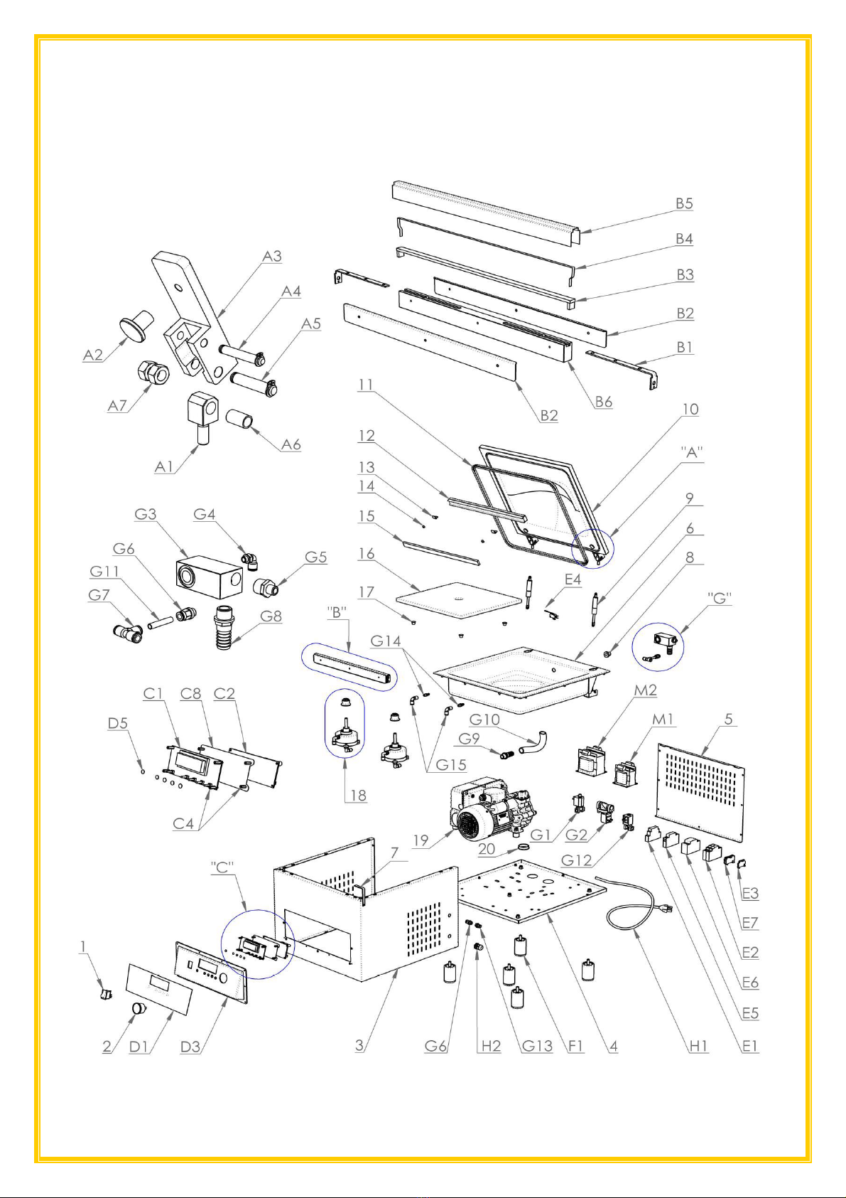
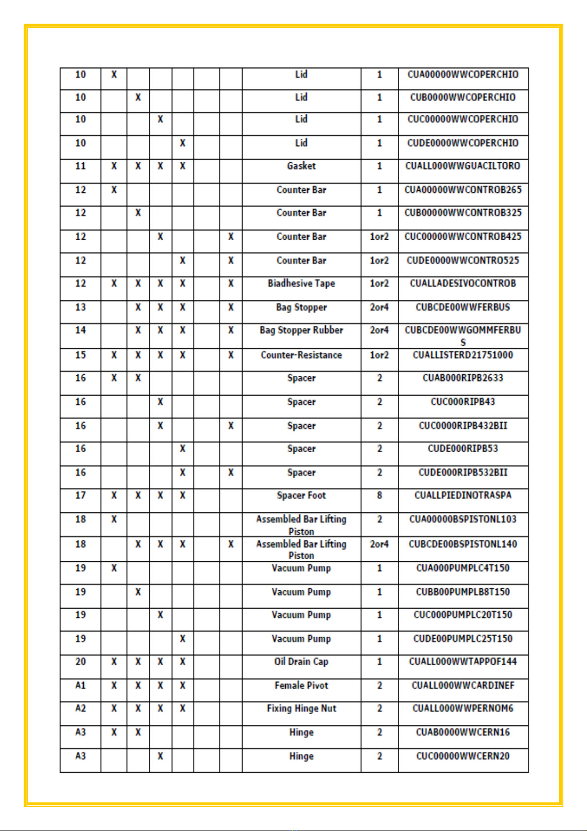
CHAPTER 11
18
EXPLODED VIEWS AND PART

19
LISTS.
20
This manual suits for next models
8
Table of contents


