Everlasting LoStagionatore STG ALL 700 INOX S ADV Instructions for use

Instruction and maintenance manualInstruction and maintenance manual
Rev.11-08
ALL-IN-ONEALL-IN-ONE
EVERTOUCHEVERTOUCH
LoStagionatore
SINCE 1956

Chapter 1 GENERAL RULES AND WARNINGS
1.1 Tests and warranty
1.2 Introduction
1.3 Product description
1.4 General safety regulations
1.5 Client’s responsibilities
1.6 Service requests
1.7 Instructions for spare parts orders
Chapter 2 SPECIFICATIONS
2.1 Dimensions
2.2 Product configurations
2.3 Power output and absorbed power
2.4 Noise level
2.5 Materials and refrigerants
Chapter 3 INSTALLATION
3.1 Transport and handling
3.2 Positioning
3.3 Wiring and electrical connection
3.4 Set-up operations
3.5 Reinstallation
3.6 Dismantling and disposal
Chapter 4 OPERATION
4.1 Applications and intended use
4.2 Safety and accident prevention
4.3 Safety data plates and guards
4.4 Operating limits
Chapter 5 ORDINARY AND PLANNED MAINTENANCE
5.1 Basic safety regulations
5.2 Cleaning operations
5.3 Periodic checks
5.4 Precautionary measures after long disuse
5.5 Preventive maintenance
Chapter 6 EXTRAORDINARY MAINTENANCE AND REPAIRS
Chapter 7 DIAGNOSTICS
Chapter 8 LO STAGIONATORE DESCRIPTION
Chapter 9 OPERATION
9.1 Installation
9.2 First Start-up
9.3 Locked Home Screen
9.4 Unlocked home Screen
Chapter 10 RECIPES
10.1 Recipe Screen
10.2 Start of Existing Recipe
10.3 Creation of New Recipe
10.4 Change and following Saving of Existing Recipe
10.5 Deleting of a Recipe
10.6 Running Recipe
INDEX
Pag. 01
Pag. 01
Pag. 01
Pag. 02
Pag. 02
Pag. 02
Pag. 02
Pag. 03
Pag. 03
Pag. 03
Pag. 03
Pag. 03
Pag. 03
Pag. 03
Pag. 04
Pag. 04
Pag. 04
Pag. 05
Pag. 05
Pag. 06
Pag. 06
Pag. 06
Pag. 06
Pag. 07
Pag. 07
Pag. 07
Pag. 08
Pag. 08
Pag. 08
Pag. 09
Pag. 09
Pag. 09
Pag. 09
Pag. 10
Pag. 11
Pag. 13
Pag. 13
Pag. 13
Pag. 13
Pag. 16
Pag. 19
Pag. 20
Pag. 29
Pag. 30
Pag. 32
Pag. 34
Pag. 35

Chapter 11 SHORTCUTS
11.1 Start_stop
11.2 Defrost
11.3 Air exchange
11.4 Rotation (optional)
11.5 Alarms
11.6 Probes
11.7 Sterilization (optional)
Chapter 12 SETUP
12.1 Date and time
12.2 Language
12.3 Connections
12.3.1 Transfers
12.3.2 Info
12.3.3 Firmware Update
12.3.4 Reboot
12.4 Parameters
Capitolo 13 SERVICE
13.1 Password access to the parameters menu
13.2 Seasoning Parameters
13.3 Alarm diagnostics
13.4 Replacement of U.V. Lamp
Pag. 39
Pag. 39
Pag. 40
Pag. 41
Pag. 41
Pag. 42
Pag. 44
Pag. 46
Pag. 47
Pag. 48
Pag. 48
Pag. 49
Pag. 49
Pag. 51
Pag. 51
Pag. 51
Pag. 51
Pag. 53
Pag. 53
Pag. 54
Pag. 56
Pag. 57

1
STAGIONATORE
Section 1: GENERAL INSTRUCTIONS
1.1 TESTING AND GUARANTEE
The appliance is tested in our works in compliance with established regulations and then shipped
ready for use.
The guarantee is valid for a full 12 months from the date of delivery of the appliance and it covers
the repair or replacement of any defective parts, with the exception of electrical and electronic
components.
Manifest defects or differences with respect to the client’s order must be communicated to the ma-
nufacturer within ve days from the receipt of the goods or they will not be covered by the guaran-
tee terms.
Any hidden or other defects must be communicated to the manufacturer within ve days from the
time that they are discovered and, in any event, within the maximum guarantee term of 12 months.
The purchaser shall be entitled only to request repair or replacement of the goods. The purchaser
is not entitled to claim compensation for direct or indirect damages of any whatsoever nature. In
any case, the right of reparation or replacement of materials will have to be exercised within the
warranty maximum time limit of 12 months from delivery date.
Repairs or replacement of defective materials will be carried out at the manufacturer’s works;
material returned to the manufacturer must be shipped carriage paid and will be returned to the
purchaser carriage forward.
1.2 INTRODUCTION
This manual has been prepared with the scope of supplying all the instructions required for the
correct use of the appliance and to maintain it in optimal condition. It also contains important user
safety information.
The following professional roles are explained in order to dene the responsibilities of each:
Installer: a qualied technician who positions the appliance and places it in service it in accordan-
ce with the instructions in this manual.
User: the person who, after reading this manual carefully, operates the appliance in accordance
with the intended use specied in this manual.
Users’ responsibilities:
- to ensure that food products are conserved at suitable temperatures and not exceeding the per-
mitted period of time
- to be aware of the regulations governing the conservation of food and to observe any whatsoever
hygiene indications that may be applicable.
The user is obliged to read the manual attentively and refer to the information in the manual at all
times.
Particular attention must be paid to the contents of heading 1.5 General Safety Warnings.
Routine Maintenance Technician: qualied technician able to perform routine maintenance of
the appliance by following the instructions in this manual (see section 5).
Special Maintenance Technician: qualied technician, authorized by the manufacturer to perform
extraordinary maintenance of the appliance (see section 6).

2
STAGIONATORE
The symbol appears at certain points in the manual to draw the reader’s attention to important
safety information.
The manufacturer declines any whatsoever responsibility in the case of improper use of the ap-
pliance deviating from the reasonably construed intended use, and for all operations carried out
that are not in compliance with the instructions laid down in the manual.
This manual must be conserved in a place that is accessible and known to all operators (installer,
user, routine maintenance technician, special maintenance technician).
This manual must not be reproduced or divulged, in whole or in part, using any whatsoever means
or in any whatsoever form.
1.3 PRODUCT DESCRIPTION
The appliance comprises a modular single body with panelling in various materials and insulation
in expanded polyurethane foam, density 42 kg/cu.m.The appliance instruments are located on the
front panel which closes the front of the motor unit, inside which the condenser unit and electrical
wiring can be housed. The refrigerator interior is tted with suitable supports for wire shelves (grids)
and/or other accessories. The doors are tted with an automatic return device and magnetic seal
elements. During the design and construction stage all measures have been adopted to implement
total safety including radiused interior corners, funnel-shaped base panel to convey condensate to
exterior, no rough surfaces, xed guards protecting moving or potentially dangerous parts.
1.4 GENERAL SAFETY REGULATIONS
Read this manual carefully and follow the prescriptions contained herein.
The user assumes full responsibility in the case of operations carried out without observing the
instructions in the manual.
Primary general safety regulations:
- do not touch the unit with wet hands and/or feet
- do not use the appliance with bare feet
- do not insert screwdrivers or other pointed objects between guards or moving parts of the appliance
- do not pull the power cord to disconnect the appliance from the electrical mains
- make sure that the appliance is not used by children or unsuitably qualied persons
- before performing any cleaning or maintenance on the appliance disconnect it from the electrical
mains by switching of
the main switch and extracting the plug
- in the case of faults or malfunctions, switch off the appliance and do not attempt to repair it
yourself. All service and repair operations must be performed exclusively by suitably qualied au-
thorized technicians.
1.5 CLIENT’S RESPONSIBILITIES
The customer is required to:
- execute the electrical and hydraulic connection of the appliance
- prepare the place of installation
- provide consumable materials for cleaning
- perform routine maintenance
- Provide adequate protection for pipes and cables external to the appliance.
In the case of power failures or malfunctions do not open the doors and drawers in order to main-
tain uniform temperature inside the unit. If the problem persists for more than a few hours, move
the food contents to a more suitable place.

3
STAGIONATORE
1.6 CLIENT SERVICE REQUESTS
For all technical problems and any requests for technical service, refer exclusively to your local dealer.
1.7 ORDERING SPARE PARTS
Spare parts orders must be made by consulting the relative spare parts catalogue which gives the
correct description of the part, the part reference code and the serial number of your appliance.
Consult your dealer.
Section 2: SPECIFICATIONS
2.1 DIMENSIONS
The overall dimensions of the units having cardboard, wooden crate and wooden box packing are
reported in TABLE 1.
2.2 PRODUCT CONFIGURATION
The appliance is designed solely for the preservation of food products (see heading 4.1).
The products must be stored in observance of the load limits shown in the table and in gure 1 in
order to ensure efcient air circulation inside the appliance (g.1).
PL
H
Type Load limits mm
Model L H P
700-1500 530 1500 650
g.1 Model Kg
700 S 100
700 C / F 150C / 100F
1500 S 200
1500 C / F 300C / 200F
2.3 POWER OUTPUT AND ABSORBED POWER
Technical data for power output and absorbed power are in the enclosed TABLE 1.
2.4 NOISE LEVEL
The noise level of the appliance is below 70 dB (A).
2.5 MATERIALS AND REFRIGERANTS
Materials in contact or potentially in contact with food products are in compliance with the relevant
directives. The appliance is designed and built so that food contact parts can be cleaned before
each use. The refrigerants utilized (R404A,) comply with established regulations, see TABLE 1.

4
STAGIONATORE
Section 3: INSTALLATION
3.1 TRANSPORT AND HANDLING
The appliance must be transported and handled exclusively in a vertical position, in observan-
ce of the instructions printed on the packing.
This precaution is necessary to avoid contamination of the refrigerant circuit with compressor lube oil
with resulting valve and heat exchanger coil failure and problems starting the electric motor.
The manufacturer accepts no responsibility for problems due to transport executed in conditions
other than those specied above.
The accessories supplied with the appliance (runners, wire shelves, basins, trays) are supplied in
separate packs shipped inside or separately from the unit.
The appliance is secured to a wooden base by means of plastic ties (g.2) and wrapped in
polyethylene or packed in a carton, cage or crate.
Refer to heading 3.6 for information on correct disposal of packing material.
The appliance must be handled using a fork lift truck or a pallet truck with suitable forks (fork
length at least equal to 2/3 length of unit).
Sizes and masses of packed units are reported in TABLE 1
Maximum permissible stacking and the position of the centre of gravity are shown on the
information label on the packing.
3.2 POSITIONING
Incorrect positioning can cause damage to the appliance and generate hazardous conditions for
personnel. The installer must therefore observe the following general regulations:
- make sure you maintain a minimum of 3 cm from the walls
- the room must be well ventilated
- keep well away from sources of heat
- avoid direct sunlight
Specic positioning procedures
- remove packing material (polyethylene, cardboard box, crate, cage)
Polyethylene is potentially dangerous to children
- remove accessories from inside the unit.
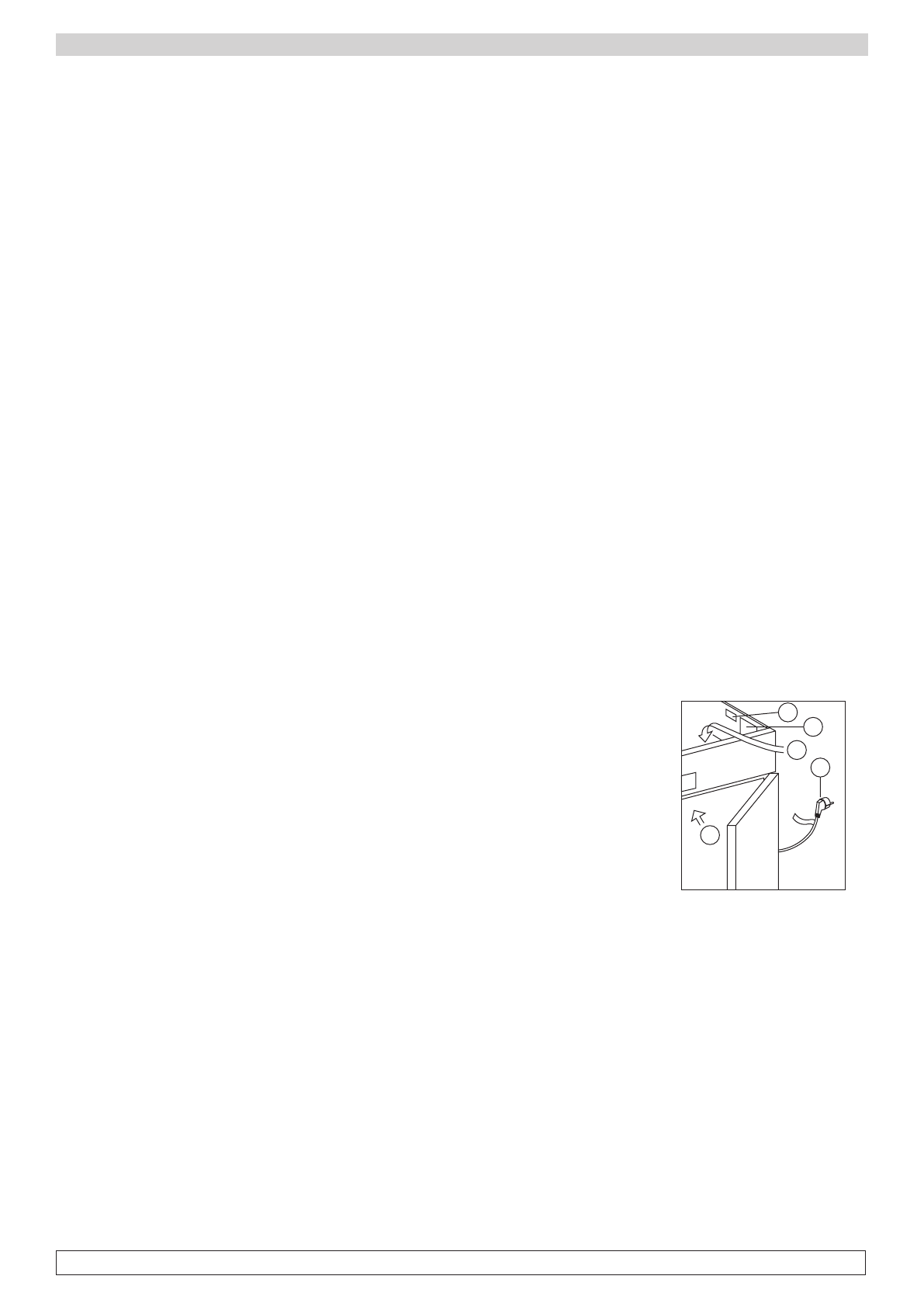
Removing the wooden base: tilt the unit sideways and cut the plastic ties (g.2) lift and remove the
base.
fig.2 fig.3 fig.4
use gloves when handling wooden packing materials and the wooden base to protect the han-
ds from splinters

5
STAGIONATORE
- position the appliance with the help of a spirit level. Adjust the leveling feet on the metal base of
the unit if necessary (g.3)
- remove the protective PVC lm from the external surfaces of the unit
- position the shelf runners in the holes in the uprights (g.4)
- insert the food shelves in the runners
- insert the condensate collection tray in the relevant runners located beneath the unit
3.3 WIRING AND ELECTRIC / WATER CONNECTION
The electrical plant and electrical hook-up operations must be
performed by a qualied electrician
For safety reasons adhere to the following indications:
- check that the electrical plant is suitably sized for the absor-
bed power of the unit
- if the electrical socket and the plug on the appliance power
cord are incompatible, change the plug with a suitable compo-
nent, ensuring the replacement part is of the approved type
- do not use reductions or multi-way adapters (g.5)
It is important to connect the appliance correctly to an efcient earth system executed in com-
pliance with the relevant legislation.
Connection to the water supply
network:
All the Seasonig cabinets need to
be connected to the water supply
network to absolve the humidity
functions.The connection
to the water supply network
must be execute according to
manufacturer’s instructions and
to professional qualied personal.
The ¾ thumb connection to the
water supply network is placed in
the engine compartment, at 200
cm high from the ground. This
cabinet need to be exclusively
connected to cold water, not
distilled and demineralized. The
working pressure needs to be
between 0,1 to 0,3 MPA.
It is advisable to install a tap to
stop the water ow in case of
maintenance.
If water is a little bit tough is
recommended to install a water
softener. Any possible solid
particles, sands for example, can
be removed installing a mechanic lter that it must be periodically checked and clean.
3.4 SET-UP OPERATIONS
To avoid errors and accidents, perform a series of checks for possible damage sustained du-
ring transport, installation and hook-up operations before starting up the unit.
fig.5

6
STAGIONATORE
Preliminary Checks
-check the condition of the power cord (no cuts or chafng)
-check that the feet, door hinges and shelf supports are stable
-check the condition of internal and external components (pipelines, heat exchanger elements,
fans, electrical components, etc.); check also that all parts are rmly xed into position
-check that the door seals and drawers are not damaged (broken or scratched) and that the doors
close and are sealed properly
The user must also observe the following instructions to obtain the best operation from the ap-
pliance:
Indications for Optimal Duty
- do not block the motor compartment air vents
- make sure doors are kept closed
- keep the defrost water drain outlet clear
- limit the frequency and duration of opening; each time the door is opened the internal temperatu-
re will alter
- perform routine maintenance regularly (see section 5).
3.5 RE-INSTALLATION
Observe the following procedure:
- switch off the appliance from the main switch
- disconnect the power cord from the electrical outlet
- handle the appliance in accordance with the instructions in heading 3.1
- follow the instructions in headings 3.2 and 3.3 for positioning and hook-ups in the new location
3.6 SCRAPPING AND DISPOSAL
Scrapping and disposal of the appliance must be carried out in full observance of established legi-
slation in your country.
Section 4: OPERATION
4.1 APPLICATIONS AND INTENDED USE
4.1.1 Intended Use and Permitted Use
The appliance is designed and built for refrigerating, preserving and storing food products on com-
mercial premises.
4.1.2 Improper and Unauthorized Use
1) treatment of products that require constant monitoring with indications in the case of temperatu-
re changes or interruption of refrigeration. For example:
- medicinal products
- blood and plasma
- thermo-sensitive chemical reactants
2) use in places subject to explosive atmosphere
7
STAGIONATORE
All uses except authorized uses of the appliance shall be construed as “improper use” for which
the manufacturer declines all responsibility.
4.2 SAFETY AND ACCIDENT PREVENTION
The appliance embodies various features designed to assure the safety and protect the health of
the user. The following list describes the protections adopted against mechanical risks:
- stability: the appliance is designed and built so that even with the shelves fully extracted in the
intended conditions of operation it will remain stable so that it can be used with no risk of tipping,
falling or sudden movement
- surfaces, edges, corners: accessible parts of the appliance have no sharp corners, sharp ed-
ges or rough surfaces that could cause injury
- moving parts: moving parts of the unit are designed, built and congured to avoid risk. Moving
parts are protected by xed guards to prevent accidental contact that could result in injury
Measures adopted for protection against additional risks:
- electrical power: the appliance is designed, built and tted out with the aim of preventing
the risk of electric shock in compliance with established safety legislation
- noise: the appliance is designed and built to reduce risks related to the emission of airborne
noise to a minimum
4.3 SAFETY DATAPLATES AND GUARDS
It is strictly forbidden (g.6):
- to tamper with or remove the evaporator cover that protects the user from the risk of cutting on
the heat exchanger ns
- to remove the dataplate xed to the inside edge of the motor housing
showing technical specications (1) and earth connection warning (2)
- to remove the dataplates on the evaporator unit cover near the elec-
trical wiring inside the motor housing which warn the user to disconnect
electrical power before working on appliance (3)
- to remove the dataplate xed inside the motor compartment indicating
earthing (4)
- to remove the data tag xed to the power cord showing the type of po-
wer supply (5)
The manufacturer declines all responsibility for safety of the appliance if
the above recommendations are not observed.
4.4 OPERATING LIMITS
The appliance is designed and built to work in ambient temperatures Max. 38°C. If the ambient
conditions are different it will not be possible to achieve the performance levels specied by the
manufacturer.
The standard power supply must be 230V +/- 10% 50Hz.
1
2
3
4
5
fig.6

8
STAGIONATORE
Section 5: ROUTINE AND PROGRAMMED MAINTENANCE
The information in this section regards the user, or other non-specialized personnel, and the routi-
ne maintenance technician.
5.1 BASIC SAFETY REGULATIONS
We summarize the safety regulations already shown in heading 1.5 to ensure that the user or
maintenance technician can perform the work in conditions of total safety:
- do not touch the unit with wet hands and/or feet
- do not use the appliance with bare feet
- do not insert screwdrivers or other pointed objects between guards or moving parts of the appliance
- do not pull the power cord to disconnect the appliance from the electrical mains
- before performing any cleaning or maintenance on the appliance disconnect it from the electrical
mains by switching of the main switch and extracting the plug
5.1.1 Prohibited: Removal of Guards and Safety Devices
It is strictly forbidden to remove guards or safety devices when performing routine maintenance
work. The manufacturer disclaims all liability that may arise if this regulation is not observed.
5.1.2 Indications on Emergency Measures in Case of Fire
- disconnect the appliance from the electrical power socket or switch off the master switch on the
electrical mains line
- do not use water to douse res
- use Co2 extinguishers
5.2 CLEANING THE REFRIGERATOR
The unit is designed to preserve food products so it is important to keep it clean for reasons of
hygiene and health. The appliance is thoroughly cleaned in our factory before delivery. We recom-
mend, however, that you clean the interior of the appliance before use. Before cleaning the ap-
pliance make sure the power cord is disconnected.
5.2.1 Cleaning the Interior and Exterior of the Appliance
- cleaning products: water and non-abrasive neutral detergent. DO NOT USE SOLVENT OR THINNERS
- cleaning method: use a cloth or sponge soaked in a suitable cleaning product to clean the interior
and exterior parts of the cabinet
- sanitation: do not use substances that could alter the taste and smell of stored food
- rinsing: use a cloth or sponge soaked un clean water. DO NOT USE WATER JETS
- frequency: once a week or at different intervals in accordance with the type of food product con-
served.
5.2.2 Cleaning the Condenser
The condenser will work less efciently if it is obstructed with
foreign material so it must be cleaned once a month. Before
cleaning the condenser switch off the appliance, disconnect the
power cord and proceed as follows:
Top-mounted unit
:-for units with xed upper front panel, use
a safe step ladder for direct access to the condenser located at
the top of the appliance. Use an air jet or a dry brush and,
A
L
C
O
O
L
fig.7

9
STAGIONATORE
working with up and down movements (g.7), remove any dust or uff that has deposited on the
heat exchanger ns. In case of greasy deposits, use a brush soaked in benzene or alcohol. For
units with overturning upper front panel, unscrew the xing screw and turn the upper panel on the
top hinges. Proceed then with the cleaning as for the models with xed upper panel. Start the ap-
pliance after cleaning.
During this operation use the following personal safety measures: safety glasses, respirator
mask, chemical resistant gloves (benzine - alcohol).
5.3 PERIODIC CHECKS
The following areas of the appliance or component assemblies require periodic checking:
- condition and efciency of the door sealing elements
- condition of hinges and correct xing of the doors
- condition of electrical cables and electrical parts
5.4 PRECAUTIONARY MEASURES FOR PROLONGED DISUSE
If the appliance is to remain unused for more than 15 days proceed as follows:
- switch off the appliance and disconnect it from the electrical supply
- clean the interior of the cabinet, shelves, trays, runners and supports, paying special attention to
critical areas such as articulations and magnetic sealing strips in accordance with the indications
in heading 5.2.
- leave doors slightly open to prevent accumulation of residual humidity
5.5 PREVENTIVE MAINTENANCE
5.5.1 Start-up after Prolonged Disuse
Before starting the appliance after prolonged disuse perform preventive maintenance. Clean the
unit thoroughly as described in heading 5.2.
5.5.2 Checking Warning and Control Devices
Check the correct running of the controls according to what is reported in the“Instruction and
Maintenance Manual” enclosed. We recommend you to take out a service or maintenance con-
tract with your dealer covering:
- cleaning of the condenser
- keeping a check on the refrigerant charge
- checking complete cycle operation
- electrical safety
Section 6: SPECIAL MAINTENANCE AND REPAIRS
All maintenance work not described in the previous sections must be considered “Special Mainte-
nance”.
Special maintenance interventions and repairs are to be performed exclusively by specialized
technicians authorized by the manufacturer.
The manufacturer declines all liability in the case of work performed by the user or unauthorized
persons, or if non-original spare parts are tted to the appliance.
10
STAGIONATORE
Section 7: DIAGNOSTIC
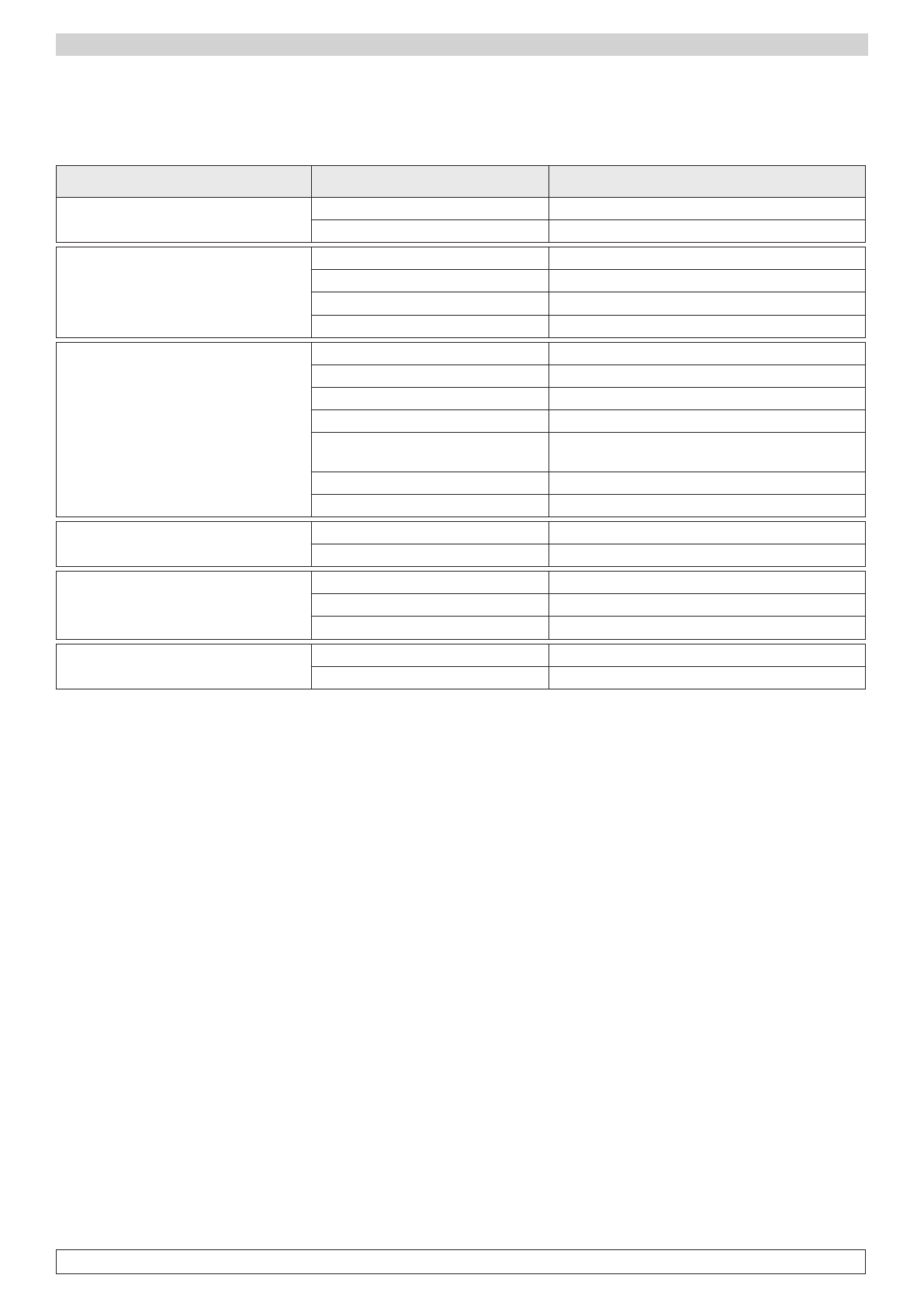
In case these problems arise, please follow the instructions stated in the following chart:
PROBLEM POSSIBLE CAUSE SOLUTION
Appliance does not switch on power failure check plug, socket, fuses, electrical line
other contact technical service
Refrigeration unit does not start set temperature has been reached set new temperature
defrosting cycle is in progress
wait for cycle to end, then switch off and on again
control panel breakdown contact technical service
other contact technical service
Refrigeration unit runs constantly,
but does not reach set temperature
room is too hot provide better ventilation
condenser is dirty clean the condenser
refrigerant needs to be recharged contact technical service
condensing fan is not running contact technical service
inefficient door seals check seals / how goods are placed inside the
cabinet
evaporator is coated with ide manual defrosting
other contact technical service
Refrigeration unit dos not stop at
set temperature
control panel breakdown contact technical service
temperature probe breakdown contact technical service
Ice block on the evaporator
improper use see section 3.4
defrost resistance breakdown contact technical service
defrost probe breakdown contact technical service
Water or ice deposits in the drip tray obstructed drain clean the drain and the drain outlet
refrigerated counter is not levelled check levelling

11
STAGIONATORE
Section 8: SEASONING CABINET
Seasoning cabinet has been designed to recreate the necessary and optimal temperature and hu-
midity conditions to season salami, cheese or meat, regardless of external weather conditions.
For instance, seasoning salami consists in giving a product a set time for resting in suitable climate
conditions, so that it can reach the best outcome in terms of organoleptic qualities, aroma and taste
in the shortest time possible.
Products must be hanged on special supports placed inside the Seasoning cabinet, so that air can
flow freely and that salami are not touching one the other.
It is also advisable to season products having the same size and type, to ensure the best result.
The Seasoning cycle can be divided into 3 main steps:
1) STEWING/DRIPPING
It lasts just a few hours: the diffusion of the aroma inside the meat is facilitated, therefore activating
the natural fermentation process and the loss of water due to gravity.
2) DRYING
It takes about six days. During this phase, the product loses a huge quantity of water. Such loss
should be as uniform as possible, alternating work and rest phases, in order to keep the gut elastic
and therefore let the water contained inside the meat reach the external part of the salami.
3) SEASONING
The duration of this phase depends on the type of product. The right regulation of humidity helps
proliferating a natural enzymatic phenomena called “good mould”, favouring the complete maturation
of the product, and capable of guaranteeing its storage and healthiness.
The EVERtouch controller manages temperature and humidity in seasoning and storage environments.
It is equipped with a 7’’ TFT display with capacitive touch screen combined with a highly-advanced
software and an extremely user-friendly interface.
As a whole, the system allows for controlling the following features: temperature (hot / cold) and
humidity (humidification / dehumidification), defrosting (electric), recoveries, dripping, air exchange
either programmed or automatic, activation of internal air recirculation for destratification and product
oxygenation.

12
STAGIONATORE
Main features:
- 7’’TFT display with high resolution (800x480 WVGA), LED backlighting and capacitive touch screen.
- Devices: USB 2.0.
- Acoustic signals.
- High quality design and icons.
- Touch screen interface with gestures, for an even more intuitive control.
- Clock and calendar (RTC).
- Multilingual.
- Software updating from USB.
- Alarm history combined with popup warning messages.
- Advanced HACCP function with detailed memory of temperature / humidity alarms triggered.
- 150 completely customizable programs can be stored on the device.
- Possibility of exporting and importing programs and parameters on USB.
- Automatic management of 20 phases for each program.
- Manual or automatic functioning with execution of the selected program.
- Diagram of the program in execution with possibility of displaying its progression (completed
phases, phases in progress and phases yet to be executed) and of representing the set values and
all remaining times.
- Temperature adjustment range: -2°C/+30°C; humidity adjustment range: 0-100 R.H.%.
- Possibility of excluding heat and humidity for managing cell-only storage with the activation of defrost cycles.
- CANBUS connection.

13
STAGIONATORE
Chapter 9: Installation and first startup
9.1 Installation
Before starting the refrigerating cabinet, it is necessary to check that all connections have been
carried out as per chapter 3.3.
9.2 First start
Once the refrigerating cabinet is connected to the power supply, the machine will begin the startup.
The display will show the uploading screen of the system software for some seconds, and then the
splash screen (fig. 8) will be displayed.
fig.8
When started, Lo Stagionatore is in STOP condition with Refrigerator as loaded recipe.
9.3 Locked Home Screen
Locked Home Screen (fig.9) is a mere visualization screen that allows increasing the safety of the
current process and avoiding accidental parameter/setting changes
fig.9

14
STAGIONATORE
ATTENTION: to change LANGUAGE or DATE and TIME, refer to paragraphs 12.1 - 12.2
It can be divided into 4 areas:
- AREA 1: The current date and time are displayed; to change the visualization format see paragraph 12.4
The name of the currently running recipe is displayed on the right.
- AREA 2: The main information about the running recipe is displayed in this area:
TEMPERATURE: The internal temperature of Lo Stagionatore is displayed in big type in the rectangle
on the left. In the underlying rectangle, Set T indicates the set-up temperature in the current phase
of the recipe.
HUMIDITY: The internal relative humidity of Lo Stagionatore is displayed in big type in the rectangle
on the right. In the underlying rectangle, Set RH indicates the set-up humidity in the current phase
of the recipe.
TIME: In the middle of AREA 2, a circular crown composed of various wedges highlights the time
progress status of the running phase. With the passing of time, the wedges become green, and when
all the wedges are highlighted, the recipe phase is completed and next phase starts. In numerical
terms, the value displayed in the middle of the crown represents the remaining time to the end of the
running phase and it can be stated in Day, Hours, Minutes.
The number of the running phase (each recipe can be composed of different phases), its name and
the remaining time to phase change are displayed inside the crown.
fig.10
The example (fig.10) indicates that the first phase ( Dry-Aging 1) of the two total phases composing
the recipe is running, and that 1 day is left to the beginning of phase 2.

15
STAGIONATORE
- AREA 3: The icons related to the statuses of the digital outputs of Lo Stagionatore are displayed:
1- Air Exchange
2 - Recovery
3 - Humidification
4 - Cooling
5 - Lighting
6 - Alarm
7 - Ventilation
8 - Warming
9 - Defrost
10 - Sterilization
11 - Cold Cuts Rotation
The output status can either be ACTIVE if it is green-coloured or NOT ACTIVE if it is white-coloured.
The last two icons on the right (sterilization and rotation) can be grey-coloured if the purchased Lo
Stagionatore model does not respectively include the germicide UV Lamp and the Cold Cuts Whirligig
rotation system.
- AREA 4: > slide to unlock
Sliding on the writing allows the unlocking of the device to access the Unlocked Home Screen

16
STAGIONATORE
9.4 Unlocked Home Screen
fig.12
The Unlocked Home Screen is an active screen, i.e. has clickable keys, unlike the Locked Home
Screen.
It can be divided in 4 areas (fig.12):
- AREA 1: It displays the current date and time; to change the visualization format see paragraph 12.1.
The name of the currently running recipe is displayed on the right.
- AREA 2: The main information about the running recipe is displayed in this area:
TEMPERATURE: The internal temperature of Lo Stagionatore is displayed in big type in the rectangle
on the left. In the underlying rectangle, Set T indicates the set temperature in the current phase of
the recipe.
HUMIDITY: The internal relative humidity of Lo Stagionatore is displayed in big type in the rectangle
on the right. In the underlying rectangle, Set RH indicates the set humidity in the current phase of
the recipe.

17
STAGIONATORE
Unlike the Locked Home Screen, the SET T and SET RH keys are clickable and allow for a quick
change of temperature and relative humidity Set Points of the running phase.
Click on the keys until fully green-coloured. (fig.13)
fig.13
The upper box will respectively display the TEMPERATURE and HUMIDITY Set Points of the running
phase; to change the values, click on the + or - keys and confirm by clicking on the SET T or ST RH
keys until fully green-coloured. (fig.14)
fig.14
The abovementioned change procedure only affects the running recipes, and it does not overwrite
the corresponding recipe that is saved in the archive.
TIME: In the middle of AREA 2, a circular crown composed of various wedges highlights the time
progress status of the running phase. With the passing of time, the wedges become green, and when
all the wedges are highlighted, the recipe phase is completed and next phase starts.
This manual suits for next models
7
Table of contents
Other Everlasting Refrigerator manuals

Everlasting
Everlasting CHOCOLATE GREEN User manual

Everlasting
Everlasting MULTILAB User manual

Everlasting
Everlasting PROFESSIONAL TRAY 05 P User manual

Everlasting
Everlasting STAGIONATOR Instructions for use

Everlasting
Everlasting BAKING CAB FL Series User manual

Everlasting
Everlasting Pastry BN 1 Installation instructions

Everlasting
Everlasting LoStagionatore MEAT Series User manual

Everlasting
Everlasting BCE2020 User manual

Everlasting
Everlasting 700 INOX Instructions for use

Everlasting
Everlasting TNV Series User manual


