EverWave Filtration EVW-AZR-4RO User manual

EverWave Filtration Azure 4-Stage RO System
Model EVW-AZR-4RO
Package Contents
(Pictures not to scale)
(A). Four-Stage RO System Head
(B). Twist-Lock Cartridges
(B1) PP Sediment Cartridge: EVW-QR-SED (RED)
(B2) Block Carbon Cartridge: EVW-QR-BLOC (WHITE)
(B3) RO Cartridge: EVW-QR-RO (GREEN)
(B4) Coconut Carbon Cartridge: EVW-QR-COCO
(BLUE)
(C). Installation Kit
(C1) Faucet with Compression Nut
(C2) Faucet Assembly
(C3) Faucet Mounting Bracket
(C4) Insert + Ferrule for Faucet
(C5) 1/4” Tubing – 5 ft. x4
a. White (INLET)
b. Blue (OUTLET)
c. Yellow (TANK)
d. Red (DRAIN)
(C6) Kitchen Faucet Adapter Valves (use one)
a. John Guest PASVPP1 (3/8”)
b. Hydranti Adapter Valve (1/2”)
(C7) Drain Clamp Assembly
(C8) Tank Adapter Valve
(C9) Clips for Tubing Connections
(C10) 3.2 Gallon Water Storage Tank
Tools and Materials
•Adjustable Wrench
•Tape Measure
•Teflon Tape
•Safety Glasses
•Masking Tape
•Newspaper or Towels
•Bucket or Pan
•1/8” Drill Bit
•Center Punch
•Drill with 1/4” & 9/16”, or 5/8” Drill Bits
•7/8” to 1” Philips Screw – (2) –OPTIONAL
•Philips Screwdriver –OPTIONAL
Stage 1: PP Sediment Cartridge: EVW-QR-SED (RED)
Stage 2: Block Carbon Cartridge: EVW-QR-BLOC (WHITE)
Stage 3: RO Cartridge: EVW-QR-RO (GREEN)
Stage 4: Coconut Carbon Cartridge: EVW-QR-COCO (BLUE)

Installation Instructions
Please read all instructions and precautions prior to installation and use.
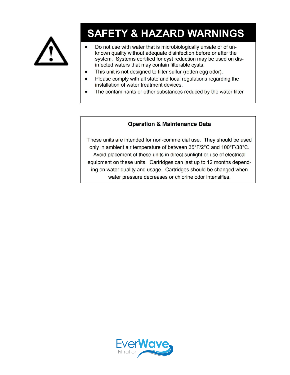
Precautions
•This filter is for cold water use only. Hot water will damage filter cartridges.
•After prolonged periods of non-use (i.e., vacation), including when first installed, it is recommended the
filter system be flushed thoroughly (let water run for 30 minutes before using).
•These cartridges have a limited service life. Changes in taste, odor, and/or water flow indicate the filter
cartridges should be replaced.
Before You Begin
•Install according to local plumbing codes.
•Try to locate a solid surface under or beside your sink. System operates best when mounted.
•Locate the cold water pipe under your sink. Rigid pipes may require cutting in order to make adequate
space to install the Feed Water Valve (C8).
•Ensure you have all appropriate fasteners and adapters to fit your plumbing.
•Visit www.EverWaveFiltration.com for tips and installation videos!
EverWave Filtration
EverWaveFiltration.com

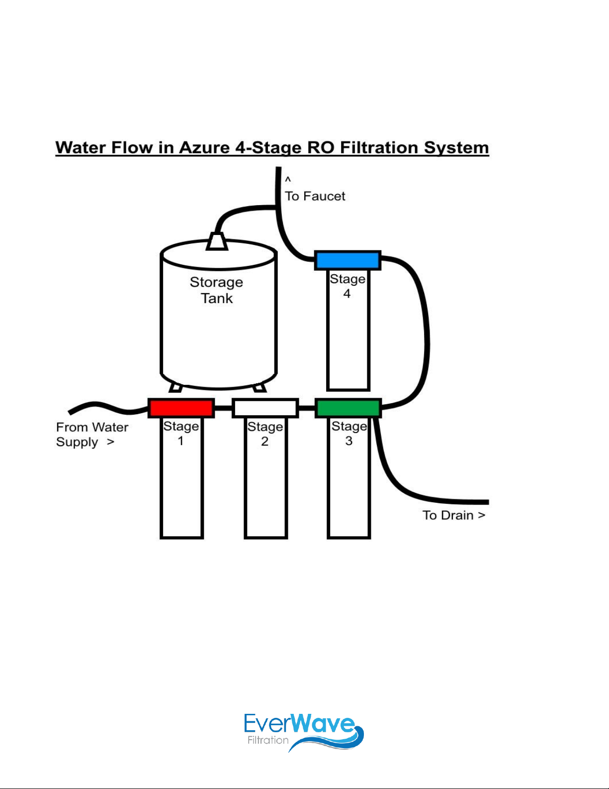
Step 1
Connect Tubing to System Head
Note: This system is packaged with colored plastic inserts in each of the inlets/outlets. These colors
correspond with the tubing that should be connected to each inlet/outlet. The following diagram shows how to
connect and disconnect tubing in this system.

Step 2
Attach Tank Adapter Valve to Water Storage Tank
1. Wrap sealing tape (not included) around the male threads on top of the tank. Circle the threads 3 full
times to ensure full coverage.
2. Screw tank adapter valve (C8) onto the water storage tank (C10). Screw until hand tight then use
wrench to make another ½ turn. Do not overtighten.
Step 3
Mount Auxiliary Faucet
Note: This faucet is designed to fit a 9/16” hole. Most standard sinks come with 1-3/8” or 1-1/2” diameter water
sprayer holes that can be used to mount this faucet. If the pre-drilled holes cannot be used or are not in the
desired position, a new hole must be drilled using either a 9/16” or 5/8” drill bit. The faucet should be positioned
securely on a flat surface with adequate space for proper function.
If you need to drill a hole, start from step (1). If you will be using a pre-drilled hole, skip to step (5). If using the
mounting bracket (C3), use 3 screws to mount the bracket to a solid surface, then skip to step (5).
1. Line sink with newspaper or towel to prevent parts and materials from falling down the drain.
2. To help prevent scratching the sink surface or countertop, apply masking tape around the area that will
be drilled.
3. Mark the drill hole using a center punch or
pencil.
4. Make a pilot hole using the 1/4” drill bit. Use
the 9/16” or 5/8” drill bit to drill the final hole.
Drill through the sink or countertop completely
and smooth rough edges with a file.
5. The first rubber gasket fits right into the base
of the faucet. Slide it into place, then guide the
faucet stem into the hole on your
counter/mounting bracket.
6. Under the counter, slide the hard plastic
washer, the small rubber washer, and the
metal gripping washer onto the stem in that
order. Tighten it all with the securing nut.
Step 4
Install the Kitchen Faucet Adapter Valve
Note: This kit includes two adapter valve options: one with 3/8” NPT connections (C6a) and one with 1/2” NPT
connections (C6b). Depending on your undersink configuration, you may need to use a different valve.
Method A (Stop Valve and Sink Supply Line can be Disconnected)
1. Locate the cold water shut-off valve under the sink. Turn off the cold water supply.
2. Turn on the kitchen faucet to release pressure and allow water to completely drain from the line.
3. Disconnect the cold water line from the 3/8” threaded stop valve under sink.
4. Holding the kitchen faucet adapter (C6a) in an upright position, screw onto the stop valve connection.
5. Screw the water supply hose, which leads to the sink, onto the open threaded end of the kitchen faucet
adapter valve. Tighten using an adjustable wrench.

Method B (Stop Valve and Sink Supply Line are Permanently Connected)
1. Locate the cold water shut-off valve under the sink. Turn off the cold water supply.
2. Turn on the kitchen faucet to release pressure and allow water to completely drain from the line.
3. Disconnect the cold water supply hose from the 1/2” threaded stem on the bottom of the kitchen faucet.
4. Holding the kitchen faucet adapter valve (C6b) in an upright position, screw onto the threaded faucet
stem.
5. Using the nut that was previously connecting the cold water line to the kitchen faucet, screw the cold
water supply line to the male threads of the adapter valve. Tighten using an adjustable wrench.
Step 5
Mount the System Head (Optional)
Note: Before mounting, be sure you have completed Step 1 correctly. Connecting tubes will be very difficult
after mounting.
1. Select an easily accessible area under the sink to mount the filter system.
2. Note: Mount system to a solid cabinet wall or wall stud. If this is not an option, use toggle bolts or
hollow-wall anchor bolts (not included) to secure the system to the surface.
3. Note: Allow a minimum clearance of 4”-6” below the filter cartridges to allow ample space for cartridge
changes. The filter system must be mounted in a vertical position.
4. Use the back panel as your mounting template, marking the holes for the mounting screws on the wall
surface.
5. Drill pilot holes for the mounting screws using a 1/8” drill bit. Insert mounting screws into the wall with a
Philips screwdriver, leaving approximately 3/8” of each mounting screw exposed.
6. Position the system head on the eyes of the bracket.
Step 6
Install White Tubing for Untreated Water from White Inlet to Kitchen Faucet Adapter Valve
Note: White tubing (C5a) should already be installed in the white inlet on the system head. Do not move
forward until ensuring you have completed Step 1 correctly.
1. Determine the length of white tubing necessary to connect the inlet to the kitchen faucet adapter,
making sure to allow enough tubing to prevent kinking in the line.
2. Cut the tubing squarely on the end not already connected to the system head. Use a tubing cutter to
ensure a square cut.
3. Without bending or crimping the tubing, wet the free end of the tubing with water and push it into the
kitchen faucet adapter approximately 5/8” until it stops. Secure connection with one of the included
clips.
Step 7
Install Yellow Tubing for Water Storage from Yellow Inlet to Tank Adapter Valve
Note: Yellow tubing (C5c) should already be installed in the yellow outlet on the system head. Do not move
forward until ensuring you have completed Step 1 correctly.
1. Screw the tank adapter valve (C8) onto the tank using thread tape to make a watertight seal. Hand
tighten the valve then twist with an adjustable wrench until tight.
2. Determine the length of yellow tubing necessary to connect the outlet to the tank adapter valve, making
sure to allow enough tubing to prevent kinking in the line.
3. Cut the tubing squarely on the end not already connected to the system head. Use a tubing cutter to
ensure square cut.

4. Without bending or crimping the tubing, wet the free end of the tubing with water and push it into the
tank adapter valve approximately 5/8” until it stops. Secure connection with one of the included clips.
Step 8
Install Blue Tubing for Treated Water from Blue Outlet to Faucet
Note: Blue tubing (C5b) should already be installed in the blue outlet on the system head. Do not move forward
until ensuring you have completed Step 1 correctly.
1. Determine the length of blue tubing necessary to connect the outlet
to the threaded faucet stem, making sure to allow enough tubing to
prevent kinking in the line.
2. Cut the tubing squarely on the end not already connected to the
system head. Use a tubing cutter to ensure a square cut.
3. Gently slide the compression nut along the tubing. Press the plastic
ferrule into the blue tubing fully. The plastic compression sleeve
goes over the tubing, between the compression nut and faucet
stem.
4. Firmly push the tubing into the end of the threaded faucet stem,
hand-tightening the plastic compression nut onto the threads.
Tighten approximately ½ turn with an adjustable wrench.
Step 9
Install Drain Clamp Assembly and Red Drain Tubing
Note: Red tubing (C5d) should already be installed in the red drain outlet on the system head. Do not move
forward until ensuring you have completed Step 1 correctly.
1. Screw 1/4” hole into drain pipe under sink. Install clamp on side of pipe, as opposed to under pipe. This
ensures drain water flows properly and does not leak.
2. Determine the length of red tubing necessary to connect the outlet to the threaded drain clamp stem,
making sure to allow enough tubing to prevent kinking in the line.
3. Cut the tubing squarely on the end not already connected to the system head. Use a tubing cutter to
ensure a square cut.
4. Assemble drain clamp with tubing as shown in the “Drain Clamp Assembly” illustration below.
5. Hand-tighten the plastic compression nut and then give it a 1/2 turn with an adjustable wrench
Step 10
Install Twist-Lock Filters
Note: When viewing the system from the front, cartridge B1 (RED) should be positioned on the far left, followed
by cartridges B2 (WHITE), B3 (GREEN), and B4 (BLUE) from right to left. The furthest right cartridge should be
B4, the blue coconut carbon post filter.
1. Hold cartridge under the appropriate part of the head with the label facing left.
2. Lift each cartridge straight up into the system head until the two extended flanges on top of cartridge
are fully engaged into the system head.
3. Turn the cartridge counter-clockwise until it stops.
4. Repeat 1-3 for each cartridge.
Step 11
Test the Filter System for Proper Operation
1. Turn on the cold water shut-off valve under the sink.
2. Turn on the new faucet for filtered water. Allow the water to run for approximately 30 minutes in order
for the filter system to flush out any air and carbon fines (fine black powder from each cartridge).
3. Check for any leaks between the system head assembly and filters, on kitchen faucet adapter valve
connection, around all fittings, and on faucet/tubing connection.
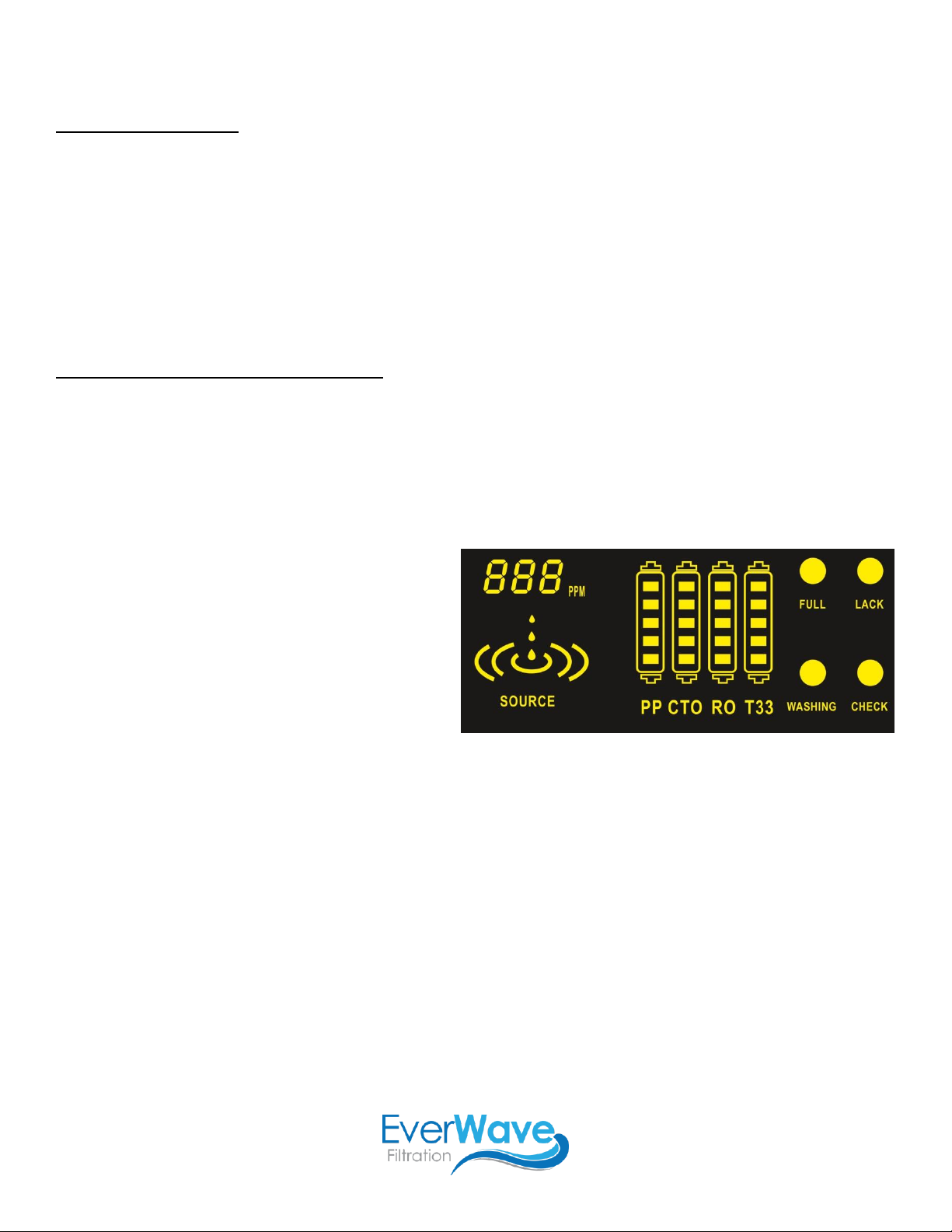
LED Display and Control Panel
•When you power on the system, the LED
display power light will turn on, a chirping
sound will play once, the screen will flash
once, and the system will auto-flush for 60
seconds. During the flush, the WASHING
icon will be flashing.
•After the system is done washing, the
system will be in a water-producing state,
with the SOURCE icon showing. This icon
means that water is being treated. When the
pressure tank is full, the SOURCE icon will turn off and the FULL icon will turn on.
•If there is a shortage of water to the device or water pressure is insufficient, the LACK icon will shine
long and bring and a buzzer will sound ten (10) times.
•When the system has produced water for 2 hours total, with no flush during that working time, it will
auto-flush for 30 seconds.
•If the system is working (producing filtered water) for 6 hours, or if a leak is detected, the machine will
automatically stop producing water. In this situation, the CHECK icon will flash and the buzzer will
sound.
•The LED display will also remind you when it is time to replace filters. The first (B1) and second (B2)
filters will last for 270 running hours, the third (B3) filter will last for 1620 hours, and the fourth (B4) filter
will last for 540 hours (all times are estimates based on averages). Each filter is shown on the display
with five (5) bars. These bars will all be full when filters are first installed. As filters are used, the bars
will empty. When the filter is completely used up, its respective icon will flash on and off. After replacing
the filter, you will need to press the RESET button to reset the filter detection timing.
•Filter Reset: To reset timing for the correct filter upon replacement, shortly press the RESET button
(less than 3 seconds). Now the RESET button will have a select function. Continue to shortly press the
RESET button until the correct filter is selected (icon will be flashing). Once you are selecting the
correct filter, long press the RESET button (over 3 seconds) until you hear a beep sound, which means

the selected filter has been reset. The filter’s icon will show with five full bars. To exit filter reset
function, short press the RESET button again after 5 seconds.
•Flushing System: Press the FLUSH button and you will hear a beeping sound once and flush will
begin. To stop flushing, press the FLUSH button again. If you press the FLUSH button while the system
is in a water-producing or full state, it will cause the RO membrane to be flushed for 120 seconds.
Troubleshooting
Cartridge Replacement
1. Turn off the cold water shut-off valve to the filter system.
2. Place a bucket or pan under the filter system to catch any water drips.
3. Turn each cartridge clockwise until it releases. Gently pull each cartridge down to remove from the
system head. Discard the used cartridges.
4. Repeat Step 9.
5. Turn on the cold water shut-off valve and the faucet for filtered water. Check for leaks. If there are
leaks, see Step 10.
6. To flush out any air and carbon fines (fine black powder), flush water through the faucet for filtered
water for approximately 30 minutes.