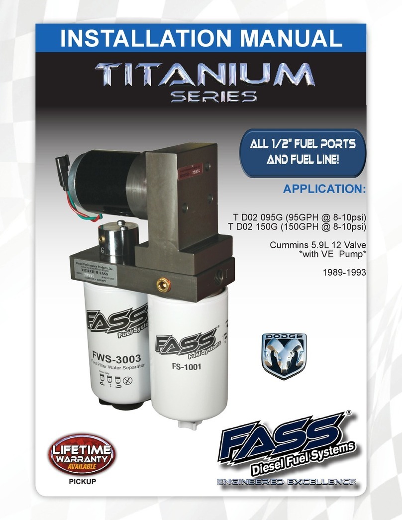
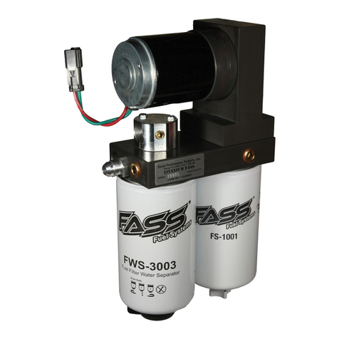
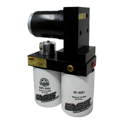
Fass HEAVY DUTY Series User manual

Part Number:
HD 150G
Application:
MBE 4000
Accessory:
FLK-S04
Revised 10-2-10

Dear Valued Customer,
“Made in the USA” is not just a slogan at FASS; it‟s what we live by! FASS is not only as-
sembled in the USA but 98%+ of the FASS product is manufactured in the USA, helping to employ
Americans and strengthen America. At FASS, we scrutinize our suppliers and demand the highest
quality American-made components. However, this does come at a price, which is one of the main
reasons FASS products are more expensive than the competition. Remember price does not dictate
quality but quality does dictate price! Here at FASS, we believe it‟s worth the commitment and will
continue this practice to support America! Our competition is doing exactly the opposite by using
foreign-made components.
Building extremely “High-Quality” fuel products is our business. We concentrate all of our
efforts in this arena. No one else is as specialized as FASS in what we do! This is one of the ingredi-
ents to insure you are running with the “Highest-Quality” fuel system in the world! We have imple-
mented very rigorous testing procedures to provide the “Highest Quality” we have become known
for. Not only is our product superior, but customer satisfaction is #1 at FASS. It is our goal to pro-
vide the best service possible. Our confidence is evident in the products we make as each product is
backed by an industry leading warranty!
Our R & D department, in conjunction with our Dealer Support department, is continually
searching for ways to improve quality, expand our product line, and provide superb support to our
network of dealers so our customers‟ needs and expectations will be exceeded.
To help insure you receive the proper system and customer support at the local level, FASS
has a VIP and Authorized Dealer network representing FASS products. This is one reason you must
purchase through a dealer to comply with our warranty policies. If you do not, there is no warranty!
We recommend you go to www.fassride.com, click “Find A Dealer”, put in their ZIP code, select the
type of dealer, and see if the company you purchased from is listed. If they are not, put their phone
number in the field below the ZIP code field to see if they are listed. Below these two fields is a list
of “Terminated/Unauthorized” dealers. You may want to review this list. If the company is not
listed or is on the “Terminated/Unauthorized” list, we suggest you return the product immediately to
that dealer and call FASS. We‟ll recommend you to the nearest dealer.
VERY IMPORTANT:Make sure to fill out your product registration form and return the
original form to FASS Fuel Systems within 30 days of purchase accompanied with a copy of the pur-
chase receipt. Complying with these guidelines will qualify you for the Extended Warranty!

STEPS TO CUSTOMER SATISFACTION
We expect every FASS System to exceed your expectation. Customer satisfaction, your satisfac-
tion, is the all-important ingredient for success to our business, as it is in any other.
Normally, technical issues can be resolved by your dealer‟s service department, as they can usu-
ally inspect the situation physically. If you‟re not satisfied with the dealership‟s response you can either
email or call FASS.
Your Name, address and daytime phone number
Model and Serial Number (Not Motor Number)
Example: Model –HD Series Serial: 00125966
Vin Number of Vehicle
Date of purchase
Nature of Problem
Call customer service; to better assist you please gather the following information before calling:
Model and Serial Number (Not Motor Number)
Example: Model –HD Series Serial: 00125966
Vin Number of Vehicle
Date of purchase
Nature of Problem

Heavy Duty Series
150 GPH / Approximately 16 PSI
This kit should not be used if your application is a “Unit Injected Mechanical Engine”. Refer to our kits with
the “UIM” label in the model number. A fuel pressure gauge is highly recommended to identify fuel filter life
and to prevent engine damage!
Machining Port Only
„H‟
Fuel Heater Port
“E”
To Engines
„T‟
Tank Fuel
Inlet Port
„R‟
Fuel Return to Tank
Machining Port Only
Serial Number Location
„H‟
Fuel Heater Port
„G‟
Gauge Port
Recommended 0-30psi

Installation Step 1: Mount Fuel System
Step 2: Return Fuel Line
Step 3: Fuel Supply Line
Step 4: Separate Return/Supply Fuel
Step 5: Install Electrical Harness
Step 6: Check Installation
Fuel System
Suggested Location:
In place of the primary fuel filter.
Factory Fuel Pump
Clean Fuel -
Removed Air, Dirt &
Water
Fuel Introduced to System
Returned Fuel
Suggested locations

Contents of Fuel Line Kit
(Bought as an Accessory) :
FLK-S04
FL-1004S x 15‟
13/32 Steel Braided Fuel Line
FL-1001G x 5‟
3/8 Rubber Fuel Line
8-212 x 5
8-250 x 2
10-298 x 4
3/8 x 1/2 (mpt x male Flare)
BF-1016
8-211 x 3
10-260 x 2
1/4 x 1/2 (fpt x mpt)
10-299
8-260 x 2
1/4 x 3/8 (fpt x mpt)
10-296 x 2
1/4 x 1/2 (mpt x male Flare)
PL-1006

Step 1:
Mounting the FASS
a. Remove frame mounted primary fuel and/or water separator.
Note: The photo‟s in this manual are from a sample of applications and are to be
used for a guideline as your specific application may be different. The text is accu-
rate and the photo again is to “ONLY” be used for a guideline.
Use thread tape or pipe sealant on “ALL” male pipe threads, do not use on male
flared fittings.
b. “ONLY” if a 90° fitting is to be used (as seen in this photo) follow these
steps:
1. Remove upside down “T” Block pump assembly by removing the 4
bolts holding it to the FASS filter base. Pay attention to the o-rings
(2) and ball(1).
2. Remove the fuel manifold and assemble 90° fitting directing it in the
correct direction.
3. Reassemble fuel manifold then pump assembly to FASS filter base
making sure all o-rings & the ball are seated in their proper place.
Attach BR-2001 to back of system using the washers and 1/4” bolts. Use
2 shortest on the system base.
c.
Position system where it will be mounted. Mark the (4) mounting points
of which prior holes may be used. Drill these marked locations with a
13/32 bit.
d.
e. Assemble to frame using the (4) - 3/8” bolts & flange nuts placing the RS-
1001 between the frame and bracket.
Apply motor oil to o-rings located on filters. Attach to system and torque
appropriately
f.

a. Locate extra ports in the fuel tanks, if there are no extra ports review the last
page of this manual. Install the 10-296 into each tank, it maybe necessary to
use a 8-260 or 10-260 to adapt fitting to tank.
b. Install 8-211(90°) or 8-212 (straight) into fuel line, part # FL-1004S using the
following procedures: recall on this procedure when necessary.
Assemble fuel line into female end (reverse threads), then apply a modest
amount of oil to the interior lining.
Secure female end in vise.
Oil male end of 8-211 and assemble into female end.
The male portion should tighten all the was as seen, be it a 90° or straight.
Step 2:
Return Fuel Line System
The fuel line being made will resemble:
From “T” to each fuel tank with 1-
straight fitting & 1-90° fitting on
each line. These lines must be the
exact length on both sides.
Return line from FASS with
straight ends to cross member
where the line will “T” off.
Assembled “T”
Assembled “T”

f. Detach the FASS return, cut this line as marked. Now assemble 8-211 into
the open end of the fuel line.
g. Connect fuel line, in discussion, to return port of the FASS and to the 10-298
of the “T” assemble, the “T” assemble with the Push-Lok fitting.
c.
Step 2: CONT.
Return Fuel Line System
Assemble the 1st “T” using (1) - 8 - 250, (2) –10-298 & (1) - 10-299 as
seen in the photo.
i. Assemble an 8-211 into an end of the open fuel line & attach to 10-298 of the
“T” assemble being covered.
d. Assemble the 2nd “T” using (1) - 8 - 250, (2) –10-298 & (1) - PL - 1001 as
seen in the photo.
e. Attach the line completed in step b to the return port of the FASS, labeled
with an “R”, route to a location where the “T” can be secured later. Measure
& mark this line as it will connect to the side fittings of the “T”. This junction
will be used later to return fuel from the engine back to the fuel tank.
h. Connect fuel line in discussion to return port of the FASS and to the 10-298
of the “T” assemble, the “T” assemble with the Push-Lok fitting.

Step 2: cont.
Return Fuel Line System
k. Cut the fuel line and assemble a 8-212 in the opposite end of the line con-
necting to the “R” port of the FASS.
l. Assemble an 8-212 into one end of the remaining fuel line. Route this
fuel line from straight fitting of the “T” to the return port in the fuel tank,
mark & cut. Caution: Route the side with the exhaust first as it will be
necessary to travel below the frame to avoid the exhaust, each side has to
be the exact same length. Later it will install as seen.
m. Cut the remaining fuel line to the “Exact” same length line as the line in
step f.
n. Assemble (1) of each 8-211 & 8-212 into each line addressed in steps f &
g.
p. Properly torque all connections and secure the fuel line & “T”.
o. In the same manner as previously covered route and loosely connect the
assembled fuel lines discussed in this section to the appropriate points of
connection including the “T”.
j. Route to the center of the nearest cross member aligned with the ports in the
fuel tank being used for return fuel. Measure & mark this line as it will con-
nect to the 90° fitting of the “T” in this location.

Step 3:
Fuel Supply Line
a. Attach the fuel supply line from the fuel tank to the FASS using a 10 - 273L
or one of the fitting from the filter housing removed in step 1.
b. Attach the fuel supply line from the FASS to the engine pump using a 10 -
273L or one of the fitting from the filter housing removed in step 1.
Step 4:
Separate return/supply fuel
a. From this location removed the banjo with 2 inlet lines & cut factory line
from bottom left hand side of the cooling plate.
Caution: There are 2 banjo washers per banjo bolts, be careful not to
loose.
e. Refer to step “A”, trace the fuel line from the banjo with 2 inlets to the rear
connecting point of the engine. This is the engine return banjo fitting, remove
this fitting, keeping track of the 2 banjo washers, separate the banjo and fuel
line.
d. Remove black engine cover located on drivers side.
b. Route FL-1001G from the cooling plate to the inlet side of the factory fuel
pump (discussed in previous step), measure and cut.
c. Apply oil to the push lok portion of the BF-1016, attach measured fuel line.
Attached open end of this fuel line, apply oil, to the exposed barb fitting of
the cooling plate.

Step 4:
Separate return/supply fuel
h. Secure fuel line and re-install engine cover.
g. Route this push lok fuel line to the area discussed in Step 2 d. Drill a 1” hole
through the engine cover to gain access to this “T”. Isolate the fuel line from
rubbing the engine cover by wrapping a piece of fuel line around the fuel line
and secure with zip ties. Apply oil to push lok fitting and attach.
f. Attach FL-1001G fuel line to this banjo fitting and re-install.

Step 5:
Installing Electrical Harness
Connect male end of WH-1001 to female connector on FASS system.
a.
Connect red wire to ignition or to the hot side of the fuse.
c.
Route the WH-1001 through a 7/16” hole in the fire wall to a power
source in the cab. Which is hot only when the key is in the ignition posi-
tion, a good source is the ignition switch or the fuel panel.
b.
Step 6:
Review Installation & Secure
a. Bolts and fasteners properly tightened?
b. Electrical harness and fuel lines secured and properly tightened?
c. Has the system been primed, refer to owners manual?
d. Check for leaks.
e. Start the engine
f. Recheck all fluid and filter connections for leaks
g. Product registration filled out and ready to be mailed or faxed.
Connect green wire to a solid clean ground, corrosion will cause issues
down the road.
d.

3 Ways of Producing Extra Ports
Most Preferred & Easiest
a. Drill and tap a 3/8”fpt in the thicker band of aluminum as seen.
b. If possible install the fuel tank vent in this port and connect the FASS return to
the vent port, for cosmetic‟s.
Not Recommended
a. Stand a 1/2” “T” on end in the place of original engine (May cause back return.
b. Route engine return to side entry and FASS return pressure to engine) in the top
of “T”.
3. Weld a Bunn
a. Fire Hazard, must be accomplished by a professional.
FASS Return
Engine Return
Fuel Tank

This manual suits for next models
1
Table of contents
Other Fass Water Filtration System manuals
Popular Water Filtration System manuals by other brands

Pentair
Pentair Posi-Chlor-15 owner's manual

SISTEM AIR
SISTEM AIR AUTO Jet TURBIX Technical manual

Clean Water Systems
Clean Water Systems 7500-REV4 installation guide

whisker
whisker Litter-Robot 4 installation guide

Katadyn
Katadyn BeFree user guide

Davey
Davey STERIFLO SF1000S mkII Installation and operating instructions

Oerlikon
Oerlikon ARS 16-25 operating instructions

PREMIER TECH
PREMIER TECH REWATEC Maxi Plus Assembly instructions and mounting guide

A.O. Smith
A.O. Smith AO-US-200 owner's manual

Sartorius stedim
Sartorius stedim 16307 Directions for use

AQUAPHOR
AQUAPHOR APRO WH 1000 LPH manual

Amaircare
Amaircare ET Annual Filter manual