Fluval 106 User manual
USER MANUAL
GUIDE DE L’UTILISATION
MANUAL DE INSTRUCCIONES
206
106
406
306
Ver.: 26/11-NA

1
2
3
4
5
6
9
8
7
10
11
1
2
3
4
5
6
8
9
7
10
11
C
A
C
A
D
B
B
206106
1
2
3
4
5
6
8
9
7
10
11 11
1
2
3
4
5
6
8
9
7
10
B
C
A
D
B
C
C
A
D
406306
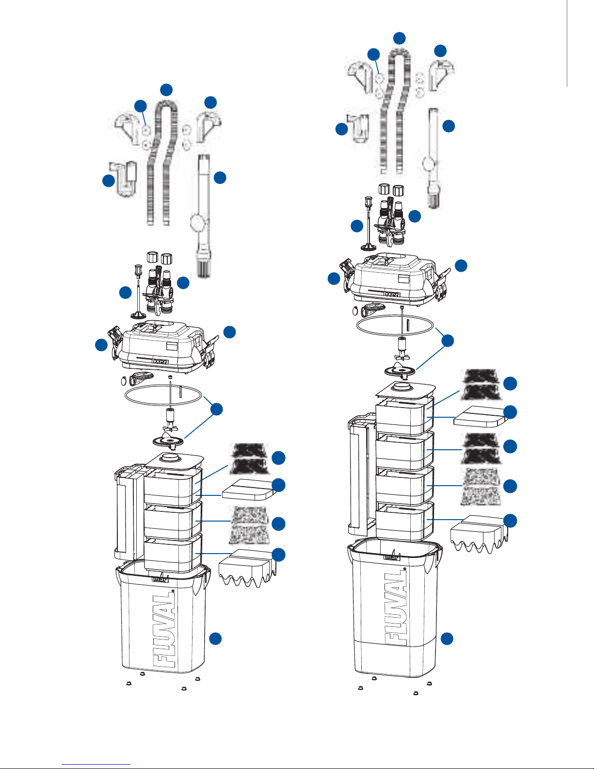
PRODUCT PARTS
1Hosing
2Rim connector assemblies (2)
3Suction cups (4)
4Intake assembly with suction cup
5Output nozzle assembly
6AquaStop valve
7Canister cover/pump housing
8Instant-prime handle (attached)
9Lift-lock clamps (attached)
10 Impeller cover and cover gasket
11 Filter canister (media baskets inside)
Refer to diagram on inside front cover.
MEDIA CONFIGURATION
MEDIA FLUVAL 106 FLUVAL 206 FLUVAL 306 FLUVAL 406
A Fluval BIOMAX 1122
B Fluval Water Polishing Pad 1122
C Fluval Carbon 112
D Fluval Bio-Foam -122
Instructions in English . . . . . . . . . . . . . . . . . . . . . .EN-1
Instructions in French . . . . . . . . . . . . . . . . . . . . . . .FR-1
Instructions in Spanish . . . . . . . . . . . . . . . . . . . . . .ES-1
CONTENTS
Refer to diagram on inside front cover. Note sequence the media was packed in, this is the recommended media placement.
FLUVAL CANISTER FILTER
EN-1 ES-22
Fluval 106 Fluval 206
Fluval 306 Fluval 406
OL
M
NJ
K
I
P
H
R
B
T
X
G
U
V
F
CD
S
A
OL
M
NJ
K
P
H
R
B
T
X
G
U
V
F
C
D
S
A
I
OL
M
NJ
K
P
H
R
B
T
X
G
U
V
F
C
D
S
A
I
OL
M
NJ
K
P
H
R
T
X
G
U
V
F
C
D
S
A
I
B
Consulte las descripciones
en la página anterior.

IMPORTA T SAFETY I STRUCTIO S
WAR I G - To guard against injury, basic safety precautions
should be observed including the following:
1.
READ & FOLLOW ALL
SAFETY INSTRUCTIONS
and all the important notices on the appliance be ore using. Failure to
do so may result in the loss o ish li e and/or damage to the appliance.
2. DANGER – To avoid possible electric shock, special care should be
taken since water is employed in the use o aquarium equipment.
For each o the ollowing situations, do not attempt repairs yoursel ,
return the appliance to an authorized service acility or service or
discard the appliance.
A. I the appliance alls into the water, DON’T reach or it!
First unplug it and then retrieve it. I electrical components o the
appliance get wet, unplug the appliance immediately.
B. Care ully examine the appliance a ter installation. It should not be
plugged i there is water on parts not intended to be wet.
C. Do not operate any appliance i it has a damaged cord or plug, or
i it is mal unctioning or it is dropped or damaged in any manner.
The power cord o this appliance cannot be replaced. I the cord is
damaged, the appliance should be discarded. Never cut the cord.
D. To avoid the possibility o the appliance plug or receptacle getting
wet, position the appliance to one side o a wall mounted
receptacle. To prevent water rom dripping onto the receptacle
or plug, a “drip loop” (see photo) should be arranged by the user
in the cord connecting appliance
to a receptacle. The “drip loop”
is that part o the cord below the
level o the receptacle or the
connector, to prevent water
travelling along the cord and
coming in contact with the
receptacle. I the plug or receptacle does get wet, DON’T unplug
the cord. Disconnect the use or circuit breaker that supplies power
to the appliance. Then unplug and examine or presence o water
in receptacle.
3. WARNING – Close supervision is necessary when any appliance is used
by or near children. This appliance is not intended or use by persons
(including children) with reduced physical, sensory or mental capabilities,
or lack o experience and knowledge, unless they have been given
supervision or instruction concerning use o the appliance by a person
responsible or their sa ety.
Children should be supervised to ensure that they do not play with
the appliance.
4. To avoid injury, do not touch moving parts or hot parts.
5. CAUTION – Always unplug or disconnect all appliances in the aquarium
rom electricity supply be ore placing hands in water, be ore putting
on or taking o parts and while the equipment is being installed,
maintained or handled.
Grasp the plug and pull to disconnect. Never yank cord to pull plug
rom outlet.
Always unplug an appliance rom an outlet when not in use.
6. This appliance is not a submersible aquarium ilter-pump. It is intended
or use in ornamental household aquariums. It may be used with resh or
salt water. Maximum water temperature 35° C.
Do not use this appliance or other than intended use (i.e.: do not use
in swimming pools, bathrooms, etc.). The use o attachments not
recommended or sold by the appliance manu acturer may cause an
unsa e condition and will invalidate your warranty.
Do not use this appliance:
a. In swimming pools or other situations where people are immersed;
b. With in lammable or drinkable liquids;
7. This is a HOUSEHOLD APPLIANCE INTENDED FOR DOMESTIC USE and it is
suitable or INDOOR use only. Do not install or store this appliance where
it will be exposed to the weather or temperatures below reezing.
8. Make sure that this appliance is securely installed be ore operating it and
that the electrical connection is in accordance with the data on the rating
label. Do not allow pump to run dry.
9. I an extension cord is necessary, a cord with proper rating should be used.
A cord rated or less amperes or watts than the appliance rating may
overheat. Care should be taken to arrange the cord so that it will not be
tripped over or pulled. The connection should be carried out by a quali ied
electrical installer.
10.
SAVETHESEINSTRUCTIONS
or uture re erence.
EN-2

EN-4
IMPORTANT
To ensure optimal and proper functioning of your
06 series Fluval External Filter, regular maintenance is required.
Failure to do so may result in the failure of the filter
and will invalidate your warranty. Additionally, regular cleaning
and maintenance will greatly reduce or completely
prevent faults and reduction in performance.
Please refer to the maintenance schedule below.
MAINTENANCE FREQUENCY
COMPONENTS MONTHLY EVERY 3 MONTHS EVERY 6 MONTHS YEARLY
Magnetic Impeller & Impeller Well Insert 1,4,7 Check & Clean
Ceramic Shaft 4Check & Clean Replace
Intake Stem/Strainer/Hosing 3Check & Clean
Ribbed Hosing Check & Clean
Primer Assembly with Primer Cover Clean & Lubricate
Gasket 2, 5 Check & Clean Clean & Lubricate Replace
AquaStop O-ring Gaskets Clean & Lubricate
Foams in the foam screen 6Check & Clean Replace
Bio-Foam 6Clean Replace
Polishing Pad 6Replace
Carbon 6Replace
BIOMAX 6Rinse Replace Half Quantity
1. Ensure Impeller Cover is fitted right way up when replacing.
2. Wet the seal ring with water before replacing. Do NOT use petroleum jelly based products.
3. Pipes will gradually block with protein slime and waste.
4. Yearly replacement ensures optimal performance.
5. The rubber seal will perish over time and will lead to leaking of canister if not replaced.
6. Refer to Fluval 06 Media instructions. Media needs replacing at dierent frequencies.
Only ever change 50% at a time.
7. Impeller and Impeller Well Insert will wear out over time. Replace as necessary.
EN-3
The Fluval 06 Series
filters oer several state of the art features to ensure
reliable operation and trouble-free maintenance.
Media is packed into filter baskets at the factory in the
recommended positions for basic filtration in order to
save you time and eliminate guesswork. The instant prime
system assures startup ease. Plus, to make maintenance
quicker, the AquaStop valve creates an air - and watertight
seal so you can disconnect hosing without breaking the
vacuum that will be necessary to resume operation without
priming. For added convenience, media baskets are
self-contained and interchangeable so that media
can be rinsed or replaced in each one, independently
of the others.
The intake assembly siphons aquarium water and
suspended debris in through its clog-proof strainer.
Water flows down through the foam screen frame,
which traps large particulate matter. The filter’s new more
powerful and silent pump then draws the water up from
the base of the unit through the media baskets for the
customized stages of mechanical, chemical, biological
and fine mechanical filtration that have been designed
through media choices and placement. Filter media
removes both waste particles and liquid impurities and can
also be actively treated to change the water’s chemical
characteristics. As water flows, it brings oxygen into the
system, feeding beneficial bacteria and breaking down
nitrogenous wastes. After passing through all baskets,
purified water enters the impeller well to be pumped back
into the output hosing. As the output nozzle disburses the
water, it creates currents that help break down wastes.
All for a continuous flow of pure water, custom treated
for a healthy, thriving aquarium environment.
Fluval MultiStage Filters
oer advanced pumping technology and a versatile
combination of mechanical, biological and chemical
filtering capabilities. This versatility enables you to
customize your aquarium environment to meet the
specialized needs of your unique collection of fish and
aquatic plants. Your filter comes with prepacked filter
media that will work well for most basic aquarium setups.
However, you have the option of selecting dierent media,
or alternative configurations of media, if you wish. Because
you have so much flexibility in selecting and positioning
media, you are able to control water characteristics with far
greater precision than with traditional filters.
In addition, Fluval 06 Series Filters provide more volume
than would be possible with round canisters of the same
outer dimensions. Increased volume means a greater
mass of filter material and a larger filtration area. Fluval
Filters multiply this advantage by directing water into
complex flow paths for greatly increased contact with
filtration media. The result? Maximum eciency, reduced
maintenance requirements, and the reliable flow of pure,
properly conditioned aquarium water.
Fluval Filters are designed and engineered for dependable
performance and ease of use. Features like click-on
rim connector assemblies for hosing and one-step lift-
lock clamps on the canister make setup and routine
maintenance quick and convenient. Plus, Fluval’s
proprietary AquaStop valve lets you disconnect, then
reconnect, the hosing without compromising the system’s
vacuum seal. This means you can stop the filter, then
restart it instantly—without priming—for quicker, easier,
more convenient maintenance.
The superior performance and capability of this filter is
backed by Fluval’s well-earned reputation for the best in
fish and aquarium care, and your assurance of the most
up-to-date and reliable research in aqua-care science.
For complete understanding of your Fluval Multi-Stage
Canister Filter and enjoyment of all its capabilities, please
read and follow these instructions for proper installation,
maintenance, and use. Failure to do so may result in loss
of fish life and/or damage to the filter.
SAVE THESE INSTRUCTIONS
FOR FUTURE REFERENCE.
INTRODUCTION
SYSTEM OVERVIEW

EN-6EN-5
AquaStop Valve
Fluval’s exclusive AquaStop valve o ers unparalleled convenience and ease o use. It creates
an air- and watertight seal that allows you to disconnect the hosing without breaking the
vacuum that keeps air out o the line. This means you can open the ilter cover or routine
maintenance and then start the system up again, with no need or priming. To stop the low o
water—instantly and completely—simply li t the AquaStop valve lever all the way up. During
iltration, you can also use the AquaStop valve lever to regulate water low, without harming
the motor or its components.
Motor
The Fluval motor is hermetically sealed to ensure reliable operation. It requires no coolant and can be placed in a closed cabinet
(where air low is restricted)
with no adverse impact on its per ormance or operating li espan. There are no moving parts, except or
the impeller.
Foam Screen Frame
The oam screen rame is vertically oriented and can be removed without having to remove the
ilter media baskets. Containing two thick layers o replaceable oam blocks to provide a highly
e icient initial stage o mechanical iltration. The large sur ace area o the oam captures
particulate waste, which will be either be broken down or held. This prevents clogging o
biological and chemical media and enhances overall ilter e ectiveness.
Intake Strainer
The intake strainer has a clog-proo , wide-mouth design to ensure steady rapid siphoning.
Output ozzle
The output nozzle delivers a continuous low o puri ied water. By dispensing water in a
strong, wide low it creates an agitation e ect that helps break down wastes and keeps
them in suspension until they can be siphoned away by the intake strainer. The more solids
that are kept a loat, the ewer settle, or cleaner, healthier aquarium sur aces.
F UVA STATE-OF-THE-ART TECHNO OGY F UVA STATE-OF-THE-ART TECHNO OGY
Media Baskets
Our system o interchangeable media baskets is the key to Fluval’s lexible iltration system.
Multiple modules allow a wide range o ilter media options or maximum versatility.
Use the basic iltration media included, or customize iltration by using your own combination
o media in each basket. Create the con iguration that’s just right or your system.
This unparalleled level o lexibility allows you to per ect your own aquatic environment.
Instant-Prime System – New and Improved
No need or manual siphoning. A simple pumping motion o the
Sel -Primer initiates water low.
Lift-lock Clamps
Securely lock cover in place. Easy to open.
Rim Connector Assemblies
The innovative rim connector assemblies slide on and snap together instantly or extra-quick
setup. They hold the intake and output hosing securely in place.

EN-8EN-7
PUMPING POWER
Flow Rates
Fluval 06 series ilters are available in our di erent models to accommodate aquariums o various sizes, rom the smallest
home tank to the largest commercial setup. They o er an outstanding array o ilter choices or the hobbyist and
pro essional aquarist alike.
The key to e ective iltration is water circulation. The more water iltered per hour, the cleaner the aquarium will remain. In
addition, water circulation is necessary to continually replenish the supply o oxygen in your aquarium. The aster a ilter
can “turn over” an aquarium’s contents
(completely iltering the entire volume o water in the tank),
the cleaner and more
highly oxygenated the water will be. Turnover rates are determined by a ilter’s volume and its low rates.
Filter Area
The greater the ilter media volume, the greater the mechanical e iciency and biological activity that will occur in the
iltration process. Fluval 06 Series ilters have been designed to maximize canister volume in all our models and to
accommodate multiple ilter media options, while at the same time increasing the pathways through the canister to give
water more contact time with the media.
Pumping Power
The more power ul the motor, the aster it can work and the more water it can pump. Each model in the Fluval 06 Series ilters is
powered by a motor engineered or top per ormance, complete reliability, and maximum e iciency with minimum noise.
Capacity Engineered: Flow Rates, Filter Areas & Power
Model recommendations to provide ideal iltration or aquarium tanks o various sizes:
F UVA AQUARIUM PUMP MECHANICA BIO OGICA FI TRATION FI TER MAX. WATER
FI TER CAPACITY OUTPUT AREA VO UME VO UME CIRCU ATION* CO UMN
MODE HEIGHT
U.S.
U.S. /Hr Sq. mm2U.S. U.S. U.S. /Hr Ft. m
Gal. Gal. Yds. Qt. Qt. Gal.
106 25 100 145 550 30,666 36,800 1.44 1.37 3.36 3.2 95 360 4.75 1.45
206 40 200 206 780 46,666 56,000 2.10 2.0 4.84 4.6 121 460 4.75 1.45
306 70 300 303 1150 46,666 56,000 3.26 3.1 6.94 6.6 206 780 5.75 1.75
406 100 400 383 1450 63,583 76,300 4.42 4.2 8.94 8.5 245 930 7.38 2.25
*Flow rates were measured with intake and output hoses that were the same length
Filter pump electrical wattages
F UVA 120 V/60 HZ230-240 V/50 HZ
FI TER E ECTRICA E ECTRICA
MODE SUPP Y SUPP Y
106 10 W 10 W
206 10 W 10 W
306 16 W 15 W
406 23 W 20 W
I STALLATIO A D USE
IMPORTA T: Read all instructions before beginning.
• For best results, top o water in aquarium be ore beginning setup.
• Allow 30-45 minutes or setup and installation.
• Tools required: Utility kni e.
(N
Noottee:: For an unusually shallow aquarium, the intake tube may need to be cut;
this requires a hacksaw.)
DO OT PLUG I FILTER U TIL SETUP IS COMPLETE A D U IT IS FILLED WITH WATER.
1. Unpack and identify all parts
Use the diagram on the inside ront cover as a guide.
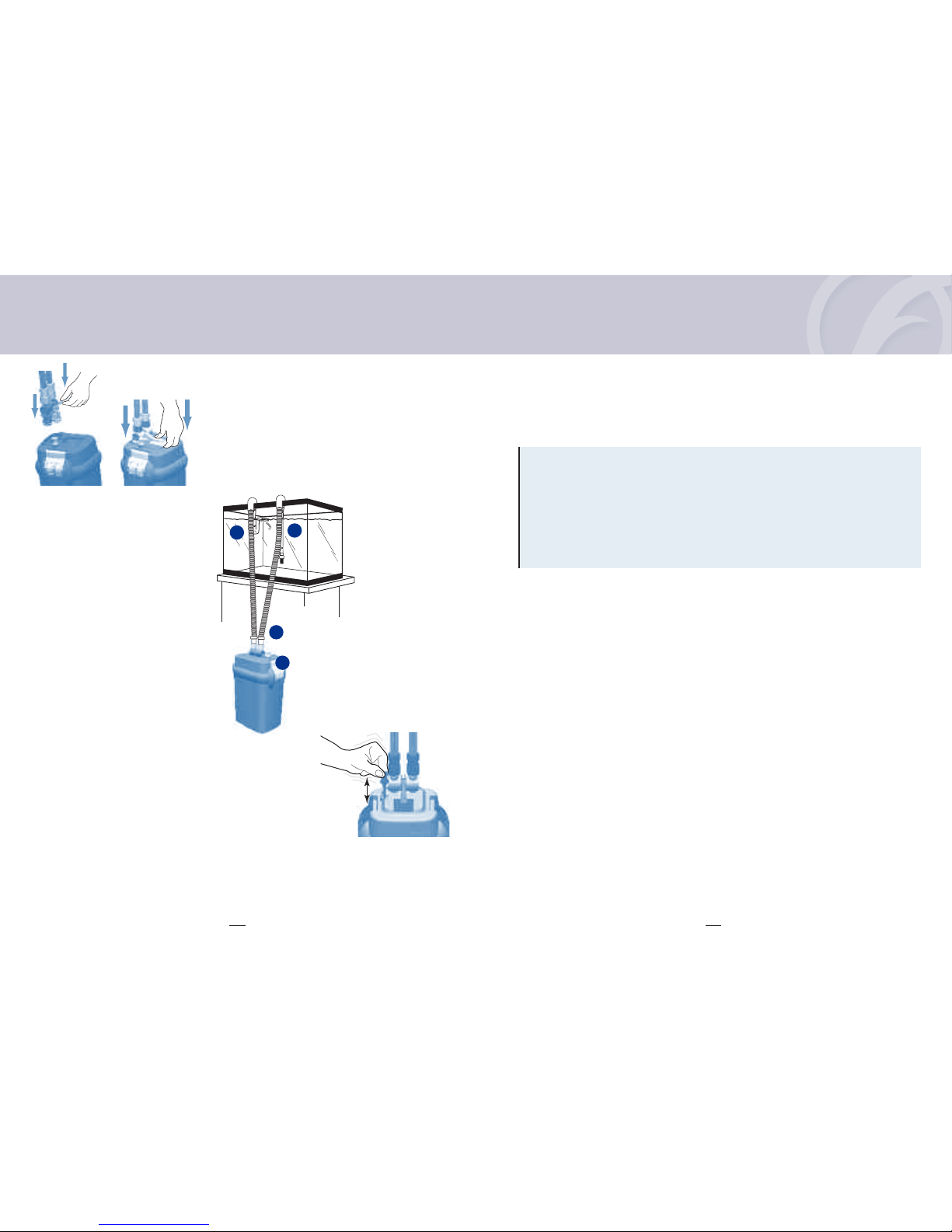
2. Prepare the aquarium
1. Decide on ilter placement. Remember, this is a gravity- ed system. For it to work properly, all the Installation
Requirements below must be adhered to.
Installation Requirements
• The canister base must never be more than 4.5 t. (1.4 m) below the water level.
• Hosing must ollow a straight path rom the ilter to the aquarium rim, with
no loops and very little slack.
• The water level should never be more than 7 in. (17.5 cm) below your
aquarium rim.
• The ilter must ALWAYS be positioned below the aquarium.
• Intake tube should not be positioned in close proximity to an air source.
2. Place the two rim connector assemblies over the back top edge o the aquarium.
Place one just above the spot where you want to position the intake tube;
place the other just above the spot where you want to position the output nozzle.
Be sure the longer section o each connector is on the outside o the aquarium.
Attach suction cups to the outside and inside section o each connector.
IMPORTA T: Be sure to position the intake tube away rom any air source—
an air stone, an aeration device, or the output valve. Air entering the intake
strainer will diminish ilter e iciency.
MAX 7 in.
(17.5 cm)
MAX 4.5 ft.
(1.4 m)

EN-10EN-9
INSTA ATION AND USE
4. Clip the suction cup onto the intake assembly near the strainer and
place the assembly in the tank, making sure the strainer is at least
3 in. (7.5 cm) rom the bottom.
(I the tube is too long or the height o
your aquarium, remove the strainer rom the intake assembly, cut the
tube with a hacksaw, and then replace the strainer.)
Once the intake
assembly is properly positioned, lock it in place by pressing the suction
cups against the glass.
5. Position the top hal o the rim connector assembly over the hosing
and push down until it “clicks” to lock the hosing in place.
4. Prepare output connections
1. The remaining length o hosing will be used or output.
Attach the hosing to the output connector (OUT) on the right side o the
AquaStop valve.
a. Push the actory- inished end o the hosing onto the valve; push it all the way,
as ar as it will go.
b. Turn the lock nut counter clockwise until it is as tight as you can make it
without orcing.
2. Measure and cut the hosing. Again, you will need a length o hosing that
reaches com ortably rom the ilter canister to inside the aquarium.
a. Stretch out the hosing so it rests over the “output” rim connector
assembly.
b. At a spot about 4 in. (10 cm) beyond the aquarium rim, use a utility
kni e to cut the hose. Do not cut the hose too short.
Remember, you can always cut it shorter during inal installation,
i necessary.
IMPORTANT: Remember, to maintain a watertight seal,
the connection point between the hosing and the output nozzle
should be kept below the water line.
"Click
to lock"
INSTA ATION AND USE
3. Prepare intake connections
1. Insert the AquaStop valve into the intake and output connectors
on the cover, and push down on the locking lever to lock it in place.
a. Position the ilter below the aquarium where it will sit while operating.
b. Attach hosing to the intake connector (IN) on the AquaStop valve;
the input connector will be on your le t.
c. Push one end o the hosing onto the valve; push it all the way,
as ar as it will go.
d. Turn the lock nut counter clockwise until it is as tight as you can make it
without orcing.
2. Measure and cut the hosing. You will need a length o hosing that reaches
com ortably rom the ilter canister to inside the aquarium.
a. Stretch out the hosing up to the top o the aquarium so it rests over the “intake”
rim connector assembly.
b. At a spot about 4 in. (10 cm) beyond the aquarium rim, use a utility kni e to cut
the hosing. Do not cut the hosing too short.
IMPORTANT: You will want the hosing to be long enough so that its connection
point with the intake assembly is always about 3 in. (7.5 cm) below the water line.
Remember, you can always cut hosing shorter during inal installation, i necessary.
3. Push the cut end o this “intake” hosing into the rubber connector on the
intake tube. Push the hosing in by at least 1 in. (2.5 cm) without twisting it.
IMPORTANT:
• Hosing must ollow a straight path with no kinks or loops and very
little slack.
• I the hosing is too long, the ilter will not work properly.
• The actory- inished end o the hosing must connect to the
AquaStop valve.
• To ensure a watertight seal, the cut end o the hosing, which connects
to the intake assembly, must be kept under water.
IN OUT
OUTIN

EN-12EN-11
INSTA ATION AND USE
3. Push the cut end o this “output” hosing into the rubber connector
at the top o the output nozzle assembly.
Push the hosing in by at least 1 in. (2.5 cm) without twisting it.
4. Place the output nozzle in the tank about 0.8 in. (2 cm) below the
water line; then push the top hal o the rim connector assembly down
until it “clicks” to lock the hosing in place.
5. Prepare the Filter
First disconnect AquaStop rom ilter and bring the ilter to a sink making sure there are no soaps or chemicals
which could contaminate the ilter.
IMPORTANT: The Bio-Foam, BIOMAX, ine pads and carbon ilter media supplied with your Fluval ilter have been
deliberately placed in Upper, Mid, and Lower level baskets to indicate their recommended placement or optimal basic
iltration. Be sure to note this positioning and place media in baskets at the same levels as you prepare the ilter or use.
1. Remove the oam screen rame, media cover, and media baskets rom the ilter
canister. The small white styro oam square must be discarded. As you remove Carbon
and BIOMAX rom baskets, note which levels they were packed in. Then remove
their outer wrappers; do not remove carbon rom porous bag(s).
2. Rinse baskets and media materials under running tap water to remove any dust,
and place media in baskets. Or, i you pre er, select other media o your own choosing.
(See “Fluval Advanced Filtration” or more in ormation.)
3. Place rinsed and illed media baskets back in canister, and put the media cover back
on top basket.
IMPORTANT: Make certain that each kind o media is positioned at the same level it
was packaged in, unless you are deliberately choosing a di erent iltration plan than the
recommended basic setup. Never over ill baskets. I baskets or cover are out o position,
cover may not close properly.
4. Rinse both sides o the oam screen rame under tap water be ore initial use to remove
any possible contaminants, and slide it back into position in the canister, lat end down.
I the screen does not seem to it properly, be sure it is not upside down.
"Click
to lock"
INSTA ATION AND USE
5. Complete canister cover assembly:
a. Lay the canister cover on a lat sur ace with its topside
down. Remove the lubricated rubber gasket rom
its plastic bag. To seal the cover opening properly,
the gasket must be moist but it need not be wet.
Care ully it the gasket into the channel around the
base o the cover.
b. Slide the impeller cover tab into the tab receptacle on
the rim o the impeller chamber. Push down the opposite side o the impeller cover making sure the impeller
starts to seat itsel in the center o the impeller cover. Continue to push down until the retailing tab “clicks” and
locks into position.
6. Place the cover on the canister. Be sure to position it properly.
There is only one orientation possible. Make certain that the
MSF logo on the cover and canister is aligned and that the
power cord its into the notch on the rim o the canister.
7. Lock the cover in place. Push the double tabs o the li t-lock
clamps under the rim; then press the upper tabs irmly against
the cover.
DO OT FILL CA ISTER WITH WATER
8. Place the unit in its inal position.
IMPORTANT REMINDERS:
• This is a gravity- ed system. For it to work properly, the ilter must be positioned vertically below the aquarium.
• The distance between the bottom o the canister and the maximum water level must not exceed 4.5 t. (1.4 m).
• Hosing must ollow a straight path rom the ilter to the aquarium rim, with no loops and very little slack.
• I hosing is too long, ilter will not work properly.
• The water level should never be more than 7 in. (17.5 cm) below your aquarium rim.
• NEVER install the ilter above the water level.
Rubber
Gasket
EN-14EN-13
INSTA ATION AND USE
9. Insert the AquaStop valve into the intake and output connectors
on the cover, and push down on the locking lever to lock it in place.
10. Open the AquaStop valve by pushing the valve lever all the way
down.
(The valves must be ully open be ore the unit is turned
on or primed.)
6. Start the filter
1. Check your installation.
a. Be sure li t-lock clamps are securely closed.
b. Make certain that the AquaStop valve is
ully open and pushed all the way down.
c. Check to see that the intake assembly
and output nozzle are both ully submersed
in water.
2. Pump the instant-prime handle by pulling it up and pushing it down,
several times, until you hear water being drawn into the unit.
Return the instant-prime handle to the down position. As water lows
through the intake hosing, it will ill the canister, pushing air out o its way.
Air will be expelled through the output nozzle, causing the water in the
aquarium to bubble. To expel all the air in the system as quickly as possible,
the AquaStop valve must be ully open.
Be sure the lever is all the way down.
cc
b
a
INSTA ATION AND USE
3. Once the bubbling in the tank stops, you’ll know the air is out o the system, and the canister is ull; plug the power
cord into an electrical outlet.
THE PUMP WILL START IMMEDIATELY.
Water should low rom the output nozzle continuously. I it does not, check your installation to be sure o the ollowing:
• No kinks or loops in the hosing.
• The base o the canister is not more than 4.5 t. (1.4 m) below the water level.
• The water is not more than 7 in. (17.5 cm) below the aquarium rim.
• The intake assembly is securely attached to the aquarium wall.
• No air is bubbling into the water at points where the intake assembly and the output nozzle connect to the hosing.
• No water is escaping rom the hosing at the AquaStop valve connection points.
• The canister cover is securely closed.
• Both levers on the AquaStop valve are both pushed all the way down.
Continue pumping the instant-prime handle until the unit starts to run on its own.
IMPORTA T: To prevent damage:
• Never plug the ilter in unless the canister is completely ull o water.
Adjusting Water Flow
Once the ilter is operating continuously, you can use the top lever on the AquaStop to regulate the water low.
To reduce the water low, li t the lever up to hal way, but no higher. This can be done once the unit is ully operational,
and will not harm the motor. However, never run the ilter with the lever up (closed) more than hal way.
Air in the Filter
Some air will become trapped in the canister as it ills; air may also be released by new media.
Eventually, the ilter will expel all air pockets. I you notice excessive bursts o bubbling over an extended period o time, check
all hosing and connections or air leaks. Also, make sure there is no air source
(such as an airstone or aeration device)
near the
intake strainer.

EN-16EN-15
FLUVAL ADVA CED FILTRATIO
The Fluval stack of media baskets
The stack o media baskets in the Fluval 06 series ilters
enables you to employ all three types o iltration in
whatever con iguration or sequence you determine is best
to meet the needs o your aquarium environment.
Filtration always begins with a mechanical stage o waste
particle removal as water lows through various oam
screens, and continues with subsequent biological and
chemical stages as it lows up through the media in
the baskets.
Because you can use the media o your choosing at each
level, you will able to design a system that provides
additional mechanical, biological and chemical iltration
i you wish.
For detailed in ormation, as well as general guidelines or
media selection please visit www. luvalaquarium.com
General Guideline
Location can determine unction: For example, BIOMAX
can act primarily as a screen or debris or act more as an
environment or growth o bene icial bacteria, depending
on where it is placed in the iltration sequence.
Proper preparation is key: Some materials, such as
Ammonia Remover, require thorough rinsing so that their
inest particles do not clog other modules or discharge into
the aquarium. For best results and the protection o your
ish, always read and ollow the preparation instructions
or the media you are using.
Use mechanical ilter media in the irst stage o iltration:
This helps ensure that the water will be as ree o debris
as possible when it lows through biological and/or
chemical ilters, which require clear water or maximum
e ectiveness.
To achieve maximum e ectiveness, Fluval 06 o ers three
types o mechanical iltration: the white oam traps the
larger particles, the black oam traps smaller particles and
the polishing pad removes the micro-particulate.
Protect chemical media rom debris: Chemical iltering
media modi ies the chemical characteristics o the water
by absorbing toxic compounds (eg, medicines, odors and
organic contaminants). The iltration e ectiveness o Fluval
activated carbon, or example, is provided by its huge
sur ace and contact with water (up to 1000 m2/g).
There ore it is necessary to prevent the chemical ilter
media rom clogging by macro and micro-particulate.
Placing chemical ilter media at the last stage o iltration
will allow it to work best.
Lower level basket
Media that continues the mechanical
capture o small particles should be
placed in the lowest media basket, to
puri y water and/or remove particles
be ore they can clog delicate pores
o biological or chemical substrates.
The Bio-Foam is ideal to remove small
dirt particles that are not retained by
the Foam Screen Frame. In addition,
this oam provides a large sur ace to
accommodate bacteria colonies,
providing an ideal environment or
proli eration o bene icial bacteria and
increasing the biological action o
Fluval BIOMAX.
Mid Level Basket(s)
The mid level basket is a good place to
begin the biological reduction process.
A lot o media types provide both
mechanical iltration and biological
treatment, creating an excellent
environment or bene icial bacteria
to proli erate. With the primary
mechanical puri ication o
the water stream occurring in the
Foam Screen Frame and the lower
basket, it is typical to load biological
media as BIOMAX into the mid level
basket.
Upper level basket
This basket receives the clearest
water, making it the ideal place
or dedicated chemical media.
Placed here, Carbon, or example,
e iciently removes discolorations,
medications and solubilized wastes
that a mechanical screen cannot.
To increase the action o chemical
ilter media and to prevent clogging
rom micro-particulate, it is suggested
to use a Polishing pad just prior to the
chemical media. The ine iltration
and chemical materials require more
requent maintenance than biological
materials and their placement at
the top makes it easier to wash
and/or replace without a ecting
the biological media.
F UVA ADVANCED FI TRATION

EN-18EN-17
MAI TE A CE
WAR I G: ALWAYS DISCO ECT ALL APPLIA CES I THE AQUARIUM FROM THE
ELECTRICAL SUPPLY BEFORE PLACI G HA DS I THE WATER, BEFORE PUTTI G
O OR TAKI G OFF PARTS, A D WHE EVER THE FILTER EQUIPME T IS BEI G
I STALLED, MAI TAI ED OR HA DLED.
Media Care
Filter Media must be periodically replaced or cleaned in accordance with instructions on individual packages. Actual li e
span o any type o media will vary based on usage and the speci ic characteristics o each aquarium. To remove and
replace media, ollow the instructions below.
IMPORTA T: Never replace all media at the same time. Stagger ilter media changes so that some older media remains
in use. This ensures re-seeding o bene icial bacteria, so that colonies discarded with old media will be replaced by vigorous
new ones. To enhance bacterial action, use Nutra in Cycle Biological Aquarium Supplement each time you change the media.
All rubber parts, cover gasket, primer stem, AquaStop Valve and seal rings should be periodically lubricated.
1. Drain the filter
1. Close the AquaStop valve by li ting the lever all the way up. This seals o the input and output hosing connections
to maintain the vacuum that is necessary in order to restart the ilter without priming.
2. Unplug the power cord.
3. Li t the locking lever to release the AquaStop valve.
It is not necessary to remove the hosing rom the AquaStop valve unless the hosing, the AquaStop valve or both
require cleaning.
(Periodic cleaning is recommended to ensure optimal water low. A good time to do this is during
a major water change. To clean, rinse under running tap water; i necessary use an appropriate Fluval Cleaning brush.)
4. Hold the unit by the canister, not the cover, and move it to an appropriate lat sur ace near a sink or other drain.
(Be sure to keep it upright to avoid spills.)
5. Release the li t-lock clamps; then push down on clamps to li t the cover/pump housing o the canister and set it aside.
6. Holding the media cover in place, tilt the canister over the sink or drain, and pour out as much water as possible.
7. Media and oam screen will be saturated with water. I your sink is not large enough to hold them, have appropriate
bucket nearby. Li t the oam screen, media cover, and media baskets out o the canister and place them in your sink
or bucket.
8. Rinse the interior o the canister with clear water. NEVER use soap or detergents when cleaning canister or rinsing
oam screen or media baskets. Traces o cleaning products may remain on sur aces and damage sensitive ish tissues.
9. Rinse the interior o the priming cylinder with clear water. Be sure the cylinder has no debris trapped in the green
lapper valve and it is sitting lush in a closed position.
MAINTENANCE
2. Clean or replace media
1. Replace chemical media, as needed. Chemical media cannot be cleaned.
2. Rinse biological media with aquarium water, never tap water, or replace as required.
Never replace all biological media at one time, as valuable colonies o bene icial bacteria would be lost.
3. Rinse screen oams and bio- oams using aquarium or de-chlorinated tap water or replace oams as needed.
For the most thorough cleaning possible, slide the oam out o the screen rame and rinse each piece separately;
rinse and wipe the screen; then reassemble. Be sure that the oam is protruding rom the top o the screen.
Rinse any other mechanical media also.
NEVER use soap or detergents on oam or screen, as traces o cleaning products could harm ish.
3. Reassemble unit
DO OT FILL CA ISTER WITH WATER WHE RE-ASSEMBLI G U IT
1. Place rinsed and illed media baskets back in canister and put cover back on top basket.
2. Replace oam screen in canister.
(Insert with lat end down.)
3. Inspect and lubricate gasket as needed.
4. Replace the cover, making certain the MSF logo and power cord are properly aligned.
5. Use the lock-li t clamps to close the cover securely.
6. Place the unit back in position; re-insert the AquaStop valve, and push down the locking lever to lock it in place.
7. Push down on the valve lever to open the AquaStop valve. Water should start lowing immediately.
IMPORTA T: I the hosing has been disconnected rom the AquaStop valve, or i the system has lost its
vacuum or some other reason, the canister will not ill automatically. Use the instant-prime handle to ill the canister.
8. Allow the canister to ill completely, then plug the power cord back into the electrical outlet.
IMPORTA T: I the canister is not ull be ore the ilter is plugged in, it may not work properly.
The ilter unit should never be allowed to run dry. Running the unit dry may result in damage to the motor.

EN-20
Fluval 06 Series External Filters are guaranteed against de ects in material and workmanship under normal
aquarium usage and service or 3 years rom date o purchase. Non-replaceable and non-serviceable parts will be
repaired or replaced at Hagen's discretion, ree o charge, when the complete ilter is returned with all components
along with a valid proo o purchase and postage paid. This warranty does not apply to any ilter that has been
subject to misuse, negligence or tampering. It does not apply to ilters which have been incorrectly assembled or
unsuitably maintained or where installation and maintenance instructions have not been ollowed correctly.
The warranty does not apply to wear and tear parts such as the impeller, impeller cover or motor seal. No liability is
assumed with respect to loss or damage to livestock or personal property irrespective o the cause thereo . Be ore
returning the ilter under warranty terms, please ensure that all setup and maintenance instructions have been
ollowed. I you are in doubt, please contact your local aquatic specialist retailer or urther advice be ore returning
the product.
THREE YEAR WARRANTY
CA ADA
CALL US TOLL-FREE AT:
1-800-554-2436
between 9:00 a.m. and 4:00 p.m.
Eastern Standard Time.
Ask or Customer Service.
FOR AUTHORISED
GUARANTEE
REPAIR SERVICE:
Return with dated receipt and $4.00
or postage and handling to:
Rol C. Hagen Inc.
Service and Repair
20500 Trans Canada Hwy
Baie d'Ur é, Québec H9X 0A2
QUESTIO S?
If you have any queries or comments about the operation of this product,
please firstly refer to your set-up and maintenance instructions.
Most issues can be resolved immediately with a little maintenance.
If you have any doubt or if you need replacement/maintenance parts,
please contact your local aquatic specialist retailer for further advice.
If you wish to seek technical advice please call or write to us
before returning the product under the warranty terms.
Most problems can be handled promptly with a phone call.
Or, i you pre er, you can contact us on our web site at www.hagen.com.
When you call (or write), please have all relevant in ormation, such as model number
and/or part numbers available, as well as the nature o the problem.
USA
CALL US TOLL-FREE AT:
1-800-724-2436
between 8:30 a.m. and 4:00 p.m.
Eastern Standard Time.
Ask or Customer Service.
FOR AUTHORISED
GUARANTEE
REPAIR SERVICE:
Return with dated receipt and $4.00
or postage and handling to:
Consumer Repairs
Rol C. Hagen (USA) Corp
305 Forbes Blvd
Mans ield, MA 02048
For more in ormation on our products, please visit our website: www.hagen.com.
EN-19
MAINTENANCE
Impeller Care
The impeller well has an e ective sel -cleaning eature. However, it is a recommended that you remove the impeller cover
and inspect the impeller as part o your routine maintenance. Keeping the impeller clean lengthens its li e and the li e o
the motor.
IMPORTA T: The impeller an has a ceramic sha t, which is resistant to wear and tear in use, but is still ragile. Handle
care ully during maintenance.
1. Remove the impeller cover: Pull the tab over and gently pry o .
2. I the impeller needs cleaning, grasp the an and draw it gently rom the well. Rinse it under clean water.
3. I the well needs cleaning, wipe gently with a Fluval Cleaning Brush.
4. Replace the impeller in the well: Slide the impeller cover tab into the tab receptacle on the rim o the impeller
chamber. Push down the opposite side o the impeller cover making sure the impeller starts to seat itsel in the
center o the impeller cover. Continue to push down until the retailing tab “clicks” and locks into position.
OTE: The ceramic impeller sha t is held on the bottom o the impeller well by a rubber support. The sha t can be easily
extracted and reinserted by hand; however, pay close attention to be certain the rubber support does not become
unseated. (Always replace the impeller cover to ensure proper alignment).
The impeller will wear out over time. A replacement may be ordered rom your local Fluval dealer or by contacting
customer service at Rol C. Hagen Corp.
Replacing the Primer
I the primer becomes damaged or worn and requires replacement, remove the
motor head rom the ilter case. Snap o the primer handle by twisting sideways.
Once the handle is removed, push the primer sha t down and remove the primer
by grasping the plunger rom the underside o the motor. Insert the new sha t with
the attached plunger, snap the primer hand back onto the primer sha t and replace
the primer cover locking it into the correct position with a “click”.
Recycling
This product bears the selective sorting symbol or waste electrical and electronic equipment
(WEEE).This means that this product must be handled pursuant to European Directive 2002/96/EC in
order to be recycled or dismantled to minimize its impact on the environment. Check with your local
Environmental Agency or possible disposal instructions or take to an o icial council registered re use
collection point. Electronic products not included in the selective sorting process are potentially
dangerous or the environment and human health due to the presence o hazardous substances.

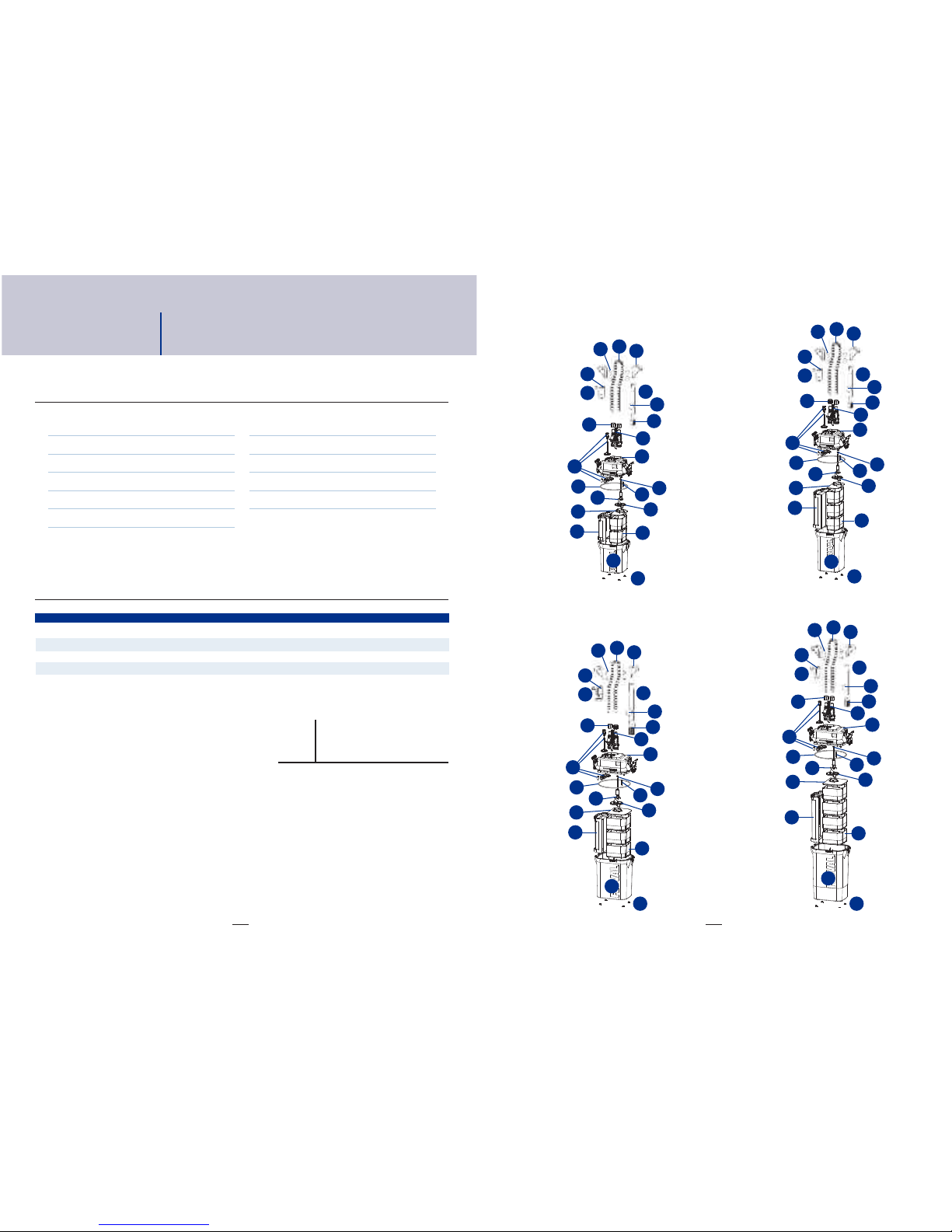
Order replacement part from your Fluval dealer
or by contacting Customer Service.
PARTS F UVA 106 F UVA 206 F UVA 306 F UVA 406
A Rubber Feet A-20121 A-20121 A-20121 A-20121
B Motor Head A-20181 A-20186 A-20191 A-20196
C Foam Insert Frame A-20122 A-20122 A-20123 A-20123
D Media Basket A-20046 A-20046 A-20043 A-20043
F Media Basket Cover A-20042 A-20042 A-20067 A-20067
G Gasket A-20038 A-20038 A-20063 A-20063
H AquaStop Valve A-20061 A-20061 A-20061 A-20061
I Intake Strainer A-20007 A-20007 A-20008 A-20008
J Intake Stem with Intake Strainer A-20010 A-20010 A-20011 A-20011
K Suction Cup (40mm) with clip A-15520 A-15520 A-15520 A-15520
L Aquarium Rim Connector A-20026 A-20026 A-20026 A-20026
M Suction Cup (30mm) A-15041 A-15041 A-15041 A-15041
N Output Nozzle A-20001 A-20001 A-20001 A-20001
O Ribbed Hosing A-20014 A-20014 A-20015 A-20015
P Hose-Lock Nuts A-20059 A-20059 A-20059 A-20059
Q Rubber Hose Connector A-20016 A-20016 A-20017 A-20017
R Primer Assembly with primer Cover A-20021 A-20021 A-20021 A-20021
S Filter Canister A-20182 A-20187 A-20192 A-20197
T Ceramic Impeller Sha t & Rubber Bushing A-20039 A-20039 A-20039 A-20039
U Magnetic Impeller with Ceramic Sha t
& Rubber Bushing A-20112 A-20112 A-20153 A-20173
V Impeller Cover A-20114 A-20134 A-20154 A-20154
X Impeller Well Insert A-20174 A-20174 A-20174 A-20174
Motor Head Maintenance Kit
Magnetic Impeller
Ceramic Sha t & Rubber Support A-20090 A-20091 A-20092 A-20093
Impeller Cover
Gasket
REPLACEME T PARTS
See ollowing page or diagrams.
EN-21 EN-22
Fluval 106 Fluval 206
Fluval 306 Fluval 406
O
M
Q
NJ
K
I
P
H
RB
T
X
G
U
V
F
CD
S
A
O
M
Q
NJ
K
P
H
R
B
T
X
G
U
V
F
C
D
S
A
I
O
M
Q
NJ
K
P
H
R
B
T
X
G
U
V
F
C
D
S
A
I
O
M
Q
NJ
K
P
H
R
T
X
G
U
V
F
C
D
S
A
I
B
See previous page or descriptions.

FR-2
PIÈCES
1Tuyaux
2Raccords des tuyaux au cadre (2)
3Ventouses (4)
4Bloc d’entrée d’eau avec ventouse
5Bec de sortie d’eau
6Soupape AquaStop
7Couvercle du boîtier/boîtier de
la pompe
8Poignée d’amorçage automatique
(attachée)
9Manettes de blocage/déblocage
instantanés (attachées au couvercle
du filtre)
10 Couvercle de la couronne et joint
d’étanchéité du couvercle
11 Boîtier du filtre (paniers de filtration
à l’intérieur)
Consulter le schéma à l'intérieur du recto de la couverture
DISPOSITION DES MASSES FI TRANTES
MASSES FI TRANTES F UVA 106 F UVA 206 F UVA 306 F UVA 406
A BIOMAX Fluval 11 2 2
B Bloc de polissage de l'eau Fluval 11 2 2
C Charbon Fluval 11 2 4
D Bio-Foam Fluval -1 2 2
Instructions en anglais . . . . . . . . . . . . . . . . . . . . . .EN-1
Instructions en rançais . . . . . . . . . . . . . . . . . . . . .FR-1
Instructions en espagnol . . . . . . . . . . . . . . . . . . . .ES-1
CO TE U
FI TRE EXTÉRIEUR F UVA
Consulter le schéma à l'intérieur du recto de la couverture. Noter l’ordre dans lequel les masses iltrantes
ont été placées; il s’agit de la disposition recommandée des masses.
FR-1
CO SIG ES DE SÉCURITÉ IMPORTA TES
AVERTISSEME T - Pour éviter toute blessure,
il faut observer des précautions élémentaires de sécurité.
1.
LIRE ET RESPECTER
TOUTES LES CONSIGNES
DE SÉCURITÉ
avant usage, ainsi que tous les avis importants apparaissant sur
l’appareil. Tout manquement à ces précautions pourrait entraîner
des dommages à l’appareil.
2. DANGER – Pour éviter tout risque d’électrocution, on doit porter
une attention spéciale à cet appareil. Dans chacune des situations
suivantes, ne pas essayer de réparer l’appareil soi-même;
le retourner plutôt à un service de réparations autorisé s’il est
encore sous garantie ou le jeter.
A. Si l’appareil tombe dans l’eau, NE PAS l’attraper : le débrancher
d’abord et ensuite le retirer. Si des pièces électriques de l’appareil
sont mouillées, on doit le débrancher immédiatement.
B. Examiner l’appareil avec soin après l’installation. Il ne devrait
pas être branché en présence d’eau sur des pièces ne devant pas
être mouillées.
C. Ne pas aire onctionner un appareil dont la iche ou le cordon
sont endommagés, qui ne onctionne pas correctement ou qui
est tombé ou a été endommagé d’une quelconque manière.
Le cordon d’alimentation de cet appareil ne peut pas être remplacé;
si le cordon est endommagé, il aut jeter l’appareil. Ne jamais
couper le cordon.
D. A in d’éviter que la iche ou la prise de courant électriques ne se
mouillent, installer l’appareil à côté d’une prise de courant murale.
Pour empêcher que l’eau ne dégoutte sur la prise ou la iche,
ormer une « boucle d’égouttement » [voir illustration] avec le
cordon d’alimentation reliant l’appareil à un réceptacle.
Cette boucle étant la partie du
cordon qui se trouve sous la prise
de courant ou le raccord et
empêche l’eau de glisser le long
du cordon et d’entrer en contact
avec la prise de courant.
Advenant que la iche ou la prise
de courant se mouille, NE PAS débrancher l’appareil. Mettre d’abord
hors circuit le usible ou le disjoncteur qui ournit l’électricité à
l’appareil et le débrancher ensuite. Véri ier qu’il n’y a pas d’eau
dans la prise.
3. AVERTISSEMENT – Une surveillance étroite est requise lorsque l’appareil
est utilisé par des en ants ou en leur présence. Cet appareil ne doit pas
être utilisé par des personnes (y compris des en ants) aux capacités
physiques, sensorielles ou mentales réduites, ou qui manquent
d’expérience et de connaissance à moins qu’elles soient placées sous la
supervision d’une personne chargée de leur sécurité ou qu’elles en aient
reçu les directives nécessaires à l’utilisation de cet appareil. Toujours
surveiller les en ants pour les empêcher de jouer avec cet appareil.
4. Pour éviter toute blessure, ne toucher aucune pièce mobile ou chaude.
5. ATTENTION – Toujours débrancher tout l’équipement dans l’aquarium
de l’alimentation électrique avant de mettre les mains dans l’eau,
d’installer ou d’enlever des pièces et pendant que l’équipement est
installé, entretenu ou manipulé. Ne jamais tirer sur le cordon électrique
pour débrancher l’appareil. Prendre la iche et débrancher l’appareil.
Toujours débrancher un appareil quand il n’est pas utilisé.
6. Cet appareil n’est pas un iltre-pompe submersible pour aquarium.
Il est conçu pour être utilisé dans le genre d’aquarium ornemental que
l’on trouve dans les domiciles. Il peut être utilisé soit pour un aquarium
d’eau douce, soit d’eau de mer. La température de l’eau ne doit pas
dépasser les 35 °C. Ne pas utiliser ce iltre pour un usage autre que celui
pour lequel il a été prévu (c.-à-d. ne pas l’utiliser dans des piscines, des
baignoires, etc.). L’utilisation de ixations ni recommandées ni vendues
par le abricant de l’appareil peut être source de situations dangereuses
et invalider votre garantie.
a. Ne pas utiliser ce iltre dans des piscines ou dans d’autres situations
où des personnes sont immergées.
b. Ne pas utiliser ce iltre avec des liquides in lammables ou potables.
7. Ce iltre est uniquement adapté à un usage DOMESTIQUE ET
À L’INTÉRIEUR. Ne pas installer ou entreposer l’appareil dans un endroit
où il sera exposé aux intempéries ou à des températures sous le point
de congélation.
8. S’assurer que le iltre est installé solidement avant de le aire onctionner
et que le branchement électrique est e ectué con ormément aux données
de raccordement inscrites sur l’étiquette. Ne pas laisser le iltre onctionner
à sec.
9. Si une rallonge électrique est nécessaire, utiliser un cordon de calibre
su isant. Un cordon de moins d’ampères ou de watts que le calibre
de l’appareil peut surchau er. Il aut prêter attention à placer le cordon
de manière à ce que personne ne trébuche ou ne tire dessus.
Le raccordement devrait être e ectué par un électricien quali ié.
10.
CONSERVER CES
INSTRUCTIONS
pour ré érence uture.

FR-4
IMPORTANT
Afin d’assurer le fonctionnement optimal et adéquat du filtre
extérieur Fluval de série 06, il faut faire un entretien régulier.
La négligence de l’entretien pourrait nuire au fonctionnement
du filtre et annulera la garantie. De plus, un nettoyage et un entretien
réguliers réduiront grandement ou préviendront complètement
les anomalies et la diminution du rendement.
Prière de consulter le calendrier d’entretien ci-dessous.
FRÉQUENCE D’ENTRETIEN
PIÈCES CHAQUE MOIS TOUS LES 3 MOIS TOUS LES 6 MOIS 1 FOIS PAR ANNÉE
Impulseur magnétique et cheville du puits de
l’impulseur 1, 4, 7 Vérifier et nettoyer
Arbre en céramique 4Vérifier et nettoyer Remplacer
Tube d’entrée d’eau/crépine/tuyaux 3Vérifier et nettoyer
Tuyau strié Vérifier et nettoyer
Bloc d’amorçage et couvercle du bloc Nettoyer et lubrifier
Joint d’étanchéité de la cuve du filtre 2, 5 Vérifier et nettoyer Nettoyer et lubrifier Remplacer
Joints d’étanchéité de l’AquaStop Nettoyer et lubrifier
Blocs de mousse dans l’épurateur-mousse 6Vérifier et nettoyer Remplacer
Bio-Foam 6Nettoyer Remplacer
Bloc de polissage de l’eau 6Remplacer
Charbon 6Remplacer
BIOMAX 6Rincer Remplacer la moitié
de la quantité
1. S’assurer que le couvercle de la couronne est bien ajusté et dirigé vers le haut
au moment de le replacer.
2. Mouiller l’anneau d’étanchéité avec de l’eau avant de le replacer.
NE PAS utiliser de produits à base de vaseline.
3. Les tuyaux bloqueront peu à peu à cause de la vase et des déchets.
4. Un remplacement annuel assure un rendement optimal.
5. L’anneau en caoutchouc s’abîmera au fil du temps et causera des fuites d’eau dans la cuve
du filtre s’il n’est pas remplacé.
6. Consulter le mode d’emploi des masses filtrantes du filtre Fluval de série 06.
Les masses filtrantes doivent être remplacées à diérentes fréquences.
Ne jamais changer plus de 50 % des masses filtrantes à la fois.
7. L’impulseur et la cheville du puits de l’impulseur s’useront avec le temps. Remplacez-les au
besoin.
FR-3
Les filtres Fluval de série 06
orent plusieurs caractéristiques perfectionnées pour
assurer un fonctionnement fiable et un entretien sans
tracas. Les masses filtrantes sont placées dans des paniers
de filtration, à l’usine, dans les positions recommandées
pour une filtration de base afin de vous faire économiser
du temps et vous éviter des hésitations. La clé d’amorçage
automatique assure un démarrage facile. De plus,
pour faciliter l’entretien, la soupape AquaStop crée
un hermétisme à l’air et à l’eau afin que vous puissiez
débrancher les tuyaux sans causer de dommages au
joint nécessaire pour démarrer le filtre sans avoir à faire
l’amorçage. Pour plus de commodité, les paniers de
filtration sont autonomes et interchangeables pour que les
masses filtrantes puissent être rincées et replacées dans
chaque panier, indépendamment des autres.
Le bloc d’entrée d’eau siphonne l’eau de l’aquarium et les
débris en suspension grâce à son épurateur antiblocage.
L’eau passe par le cadre de l’épurateur-mousse qui retient
les matières en grosses particules. La nouvelle pompe
du filtre, plus puissante et silencieuse que l’ancienne, fait
ensuite passer l’eau du fond vers le haut par les paniers
de filtration et les étapes perfectionnées de filtration
mécanique, chimique et biologique et de filtration
mécanique fine, dans l’ordre choisi. Les masses filtrantes
enlèvent autant les déchets en particules que les impuretés
liquides de l’eau et elles peuvent être traitées activement
pour changer la composition chimique de l’eau. Lorsque
l’eau passe dans le système, elle amène de l’oxygène,
nourrissant les bactéries bénéfiques et détruisant les
déchets azotés. Après avoir circulé dans tous les paniers de
filtration, l’eau purifiée entre dans le puits de la couronne
pour ensuite être pompée dans le tuyau de sortie d’eau.
Le bec de sortie d’eau renvoie l’eau dans l’aquarium,
créant des courants qui aident à détruire les déchets.
Tout pour un débit d’eau pure, traitée pour créer un milieu
aquatique sain et florissant.
Le système de filtration multiétapes Fluval
ore une pompe de technologie avancée et une
combinaison polyvalente de filtration mécanique,
biologique et chimique. Cela vous permet de personnaliser
votre aquarium pour répondre aux besoins spécialisés
de votre collection unique de poissons et de plantes
aquatiques. Votre filtre comprend des masses filtrantes
préemballées qui seront adaptées à la plupart des
aquariums de base. Toutefois, vous avez la possibilité
de choisir diérentes masses filtrantes ou d’autres
configurations pour celles-ci, si vous le désirez. Parce que
vous avez la possibilité de choisir et de positionner vos
masses filtrantes, vous êtes en mesure de contrôler les
caractéristiques de l’eau de façon beaucoup plus précise
qu’avec les filtres traditionnels.
Par ailleurs, les filtres Fluval de série 06 orent une
filtration supérieure de 35 à 55 % aux contenants ronds
de mêmes dimensions extérieures. Un volume amélioré
signifie une plus grande surface de masse filtrante et,
par le fait même, de filtration. Les filtres Fluval multiplient
ces avantages en faisant circuler l’eau dans des circuits
complexes pour un meilleur contact avec les masses
filtrantes. Le résultat? Une ecacité maximale, des besoins
d’entretien réduits et le débit fiable d’une eau d’aquarium
pure et bien traitée.
Les filtres Fluval sont conçus et fabriqués pour assurer la
performance et la facilité d’utilisation. Des caractéristiques
comme les raccords des tuyaux au cadre et les manettes
de blocage/déblocage en une étape sur le boîtier rendent
l’installation et l’entretien de routine rapides et simples.
Et la soupape AquaStop des filtres Fluval vous permet de
débrancher et de rebrancher les tuyaux sans compromettre
l’hermétisme du joint du système. Cela signifie que vous
pouvez arrêter le filtre et le redémarrer instantanément,
sans amorçage, pour un entretien rapide, simple et pratique.
La performance et l’ecacité supérieures de ce filtre sont
soutenues par la réputation bien méritée de Fluval d’orir
le meilleur aux poissons et pour les soins des aquariums,
ainsi que par la certification de la Station Hagen de
recherche en aquariophilie, votre assurance des recherches
les plus fiables et les plus récentes dans la science des soins
aquatiques.
Pour une compréhension complète de votre système de
filtration multiétapes Fluval extérieur, et pour profiter de
toutes ses capacités, veuillez lire et suivre attentivement
ces instructions afin d’assurer l’installation, l’entretien
et l’utilisation appropriés. Si vous ne le faites pas, vous
pourriez perdre des poissons ou endommager votre filtre.
CONSERVER CES INSTRUCTIONS POUR RÉFÉRENCE
FUTURE.
INTRODUCTION
APERÇU DU SYSTÈME

FR-6
Soupape AquaStop
La soupape AquaStop exclusive à Fluval o re une commodité et une acilité d’utilisation
inégalées. Elle crée un hermétisme à l’air et à l’eau qui vous permet de débrancher les tuyaux
sans compromettre la succion qui permet de garder l’air à l’extérieur de ceux-ci.
Cela signi ie que vous pouvez ouvrir le couvercle pour l’entretien de routine et redémarrer
le système sans avoir besoin de aire l’amorçage. Pour arrêter le débit d’eau, instantanément
et complètement, lever simplement la manette de la soupape AquaStop vers le haut.
Durant la iltration, vous pouvez aussi utiliser la manette de la soupape AquaStop pour régler
le débit d’eau, sans risquer d’endommager le moteur ou ses pièces.
Moteur
Le moteur du iltre Fluval est scellé hermétiquement pour assurer un onctionnement iable. Il ne nécessite pas de liquide
de re roidissement et peut être placé dans un meuble ermé
(où la circulation d’air est restreinte)
sans e et négati sur sa
per ormance ou sa durabilité. Il ne possède pas de pièces mobiles, excepté la couronne.
Cadre de l’épurateur-mousse
Le cadre de l’épurateur-mousse est placé à la verticale de açon à pouvoir le retirer sans avoir à
enlever les paniers des masses iltrantes. Il contient deux couches épaisses de blocs de mousse
remplaçables pour ournir une première étape de iltration mécanique extrêmement e icace.
La sur ace massive de la mousse attrape les déchets en particules qui seront alors décomposés
ou retenus. Cela empêche le blocage des masses iltrantes biologiques et chimiques et améliore
l’e icacité générale du iltre.
Crépine d’admission
La crépine d’admission à embouchure large empêche les blocages et assure
un siphonnage rapide et constant.
Bec de sortie d’eau
Le bec de sortie d’eau libère un lot constant d’eau puri iée. En dirigeant l’eau en un débit
large et ort, le bec crée un e et d’agitation qui aide à décomposer les déchets et à les
maintenir en suspension jusqu’à ce qu’ils soient siphonnés par la crépine d’admission.
Ainsi, plus il y a de solides qui demeurent en suspension, moins il y en aura qui
s’accumuleront; les sur aces et l’eau en seront donc d’autant plus propres.
TECHNO OGIE PERFECTIONNÉE F UVA
FR-5
TECHNO OGIE PERFECTIONNÉE F UVA
Paniers de filtration
Notre système de paniers interchangeables est la clé du système lexible de iltration Fluval.
Plusieurs modules permettent d’utiliser une importante variété de masses iltrantes pour une grande
polyvalence. Utiliser les masses iltrantes de base incluses ou personnaliser la iltration en employant
votre propre combinaison de masses iltrantes dans chaque panier. Créer la con iguration qui convient
le mieux à votre système. Ce niveau incomparable de lexibilité vous permet de per ectionner votre
propre milieu aquatique.
Système d’amorçage automatique – Nouveau
et amélioré par rapport au modèle précédent
Le système ne nécessite pas de siphonnage manuel.
Un simple pompage de la clé d’amorçage déclenche le débit d’eau réglé.
Manettes de blocage/déblocage instantanés
Permettent de verrouiller solidement le couvercle en place.
Les manettes s’ouvrent acilement.
Raccords des tuyaux au cadre
Pour une installation très rapide, les raccords innovateurs des tuyaux
au cadre glissent sur le cadre et sont ixés instantanément.
Ils maintiennent solidement en place les tuyaux d’entrée et de sortie d’eau.

PUISSANCE DE POMPAGE
Débits d’eau
Les iltres Fluval de série 06 sont o erts en quatre modèles pour convenir à des aquariums de dimensions variées, du plus
petit aquarium de maison aux installations commerciales. Ils o rent une gamme remarquable de iltres pour les amateurs
comme pour les aquariophiles pro essionnels.
La clé d’une bonne iltration est la circulation de l’eau. Plus d’eau est iltrée à l’heure, plus l’aquarium restera propre.
De plus, la circulation de l’eau est nécessaire pour re aire le plein d’oxygène dans votre aquarium. Plus rapidement un iltre
peut « renouveler » l’eau d’un aquarium
( iltrer entièrement le volume total d’eau dans l’aquarium)
, plus l’eau sera propre
et bien oxygénée. La vitesse du renouvellement est déterminée par la contenance du iltre et par la circulation de l’eau iltrée.
Aire de filtration
Plus le volume de la masse iltrante est élevé, plus grandes sont l’e icacité mécanique et l’activité biologique dans le
processus de iltration. Les iltres Fluval de série 06 ont été conçus pour maximiser le volume du boîtier des quatre modèles
et pour pouvoir contenir plusieurs types de masses iltrantes, tout en augmentant les passages de l’eau dans le boîtier a in
que l’eau soit en contact plus longtemps avec la masse iltrante.
Puissance de la pompe
Plus le moteur est puissant, plus vite la pompe peut travailler et plus elle peut pomper d’eau.
Chacun des iltres Fluval de série 06 est muni d’un moteur conçu pour une per ormance supérieure, une iabilité complète
et une e icacité maximale, et de açon aussi peu bruyante que possible.
Capacités mises au point : débits d’eau, aire de filtration et puissance
selon le modèle de filtre
Ci-dessous se trouvent les modèles de iltres idéaux recommandés pour les di érentes grandeurs d’aquariums :
MODÈ E
MODÈ E CONTENANCE RENDEMENT SURFACE VO UME VO UME DE CIRCU ATION HAUTEUR
DU FI TRE DE DE A DE FI TRATION BIO OGIQUE FI TRATION DE ’EAU MAXIMA E DE
F UVA ’AQUARIUM POMPE MÉCANIQUE FI TRÉE* A CO ONNE
Gal
Gal /h Verges m2Pintes Pintes Gal /h Pieds m
US US/h carrées US US US/h
106 25 100 145 550 30 666 36 800 1,44 1,37 3,36 3,2 95 360 4,75 1,45
206 40 200 206 780 46 666 56 000 2,10 2,0 4,84 4,6 121 460 4,75 1,45
306 70 300 303 1150 46 666 56 000 3,26 3,1 6,94 6,6 206 780 5,75 1,75
406 100 400 383 1450 63 583 76 300 4,42 4,2 8,94 8,5 245 930 7,38 2,25
*Les débits ont été mesurés avec des tubes d’entrée et de sortie d’eau de la même longueur.
Puissance électrique de la pompe des filtres
MODÈLE DE COURANT DE COURANT DE
FILTRE FLUVAL 120 V/60 HZ 230-240 V/50 HZ
106 10 W 10 W
206 10 W 10 W
306 16 W 15 W
406 23 W 20 W
I STALLATIO ET UTILISATIO
IMPORTA T : Lire toutes les instructions avant de commencer.
• Pour de meilleurs résultats, remplir l’aquarium d’eau avant de commencer.
• Prévoir de 30 à 45 minutes pour la préparation et l’installation.
• Outils requis : couteau tout usage.
(N
Noottee :: Pour un aquarium inhabituellement peu pro ond, le tube d’entrée
peut devoir être coupé. Vous aurez alors besoin d’une scie à métaux.)
E PAS BRA CHER LE FILTRE AVA T QUE L’I STALLATIO SOIT COMPLÉTÉE
ET QUE L’AQUARIUM SOIT REMPLI D’EAU.
1. Déballer et identifier toutes les pièces
Utiliser, comme guide, le schéma à l’intérieur du recto de la couverture.
2. Préparer l’aquarium
1. Décider de l’emplacement du iltre. Ne pas oublier qu’il s’agit d’un système par gravité.
A in qu’il onctionne correctement, toutes les directives d’installation ci-dessous doivent être respectées.
Directives d’installation
• La base du boîtier ne doit jamais se trouver à plus de 1,4 m (4,5 pi)
sous le niveau de l’eau.
• Le tuyau doit suivre un chemin direct du iltre au cadre de l’aquarium,
avec un peu de jeu, mais sans boucle.
• Le niveau de l’eau ne devrait jamais être à plus de 17,5 cm (7 po)
sous le cadre de l’aquarium.
• Le iltre doit TOUJOURS être placé plus bas que l'aquarium.
• Le tube d’entrée d’eau ne devrait pas être positionné à proximité d’une
source d’air.
2. Placer les deux raccords des tuyaux au cadre sur le bord arrière de l’aquarium.
En placer un juste au-dessus de l’endroit où vous voulez mettre le tube d’entrée
et un autre juste au-dessus de l’endroit où vous voulez positionner le bec de sortie
d’eau.
S’assurer que la section la plus longue de chacun des raccords est à
l’extérieur de l’aquarium.
IMPORTA T : S’assurer de placer le tube d’entrée loin de toute source d’air
(pierre à air, dispositi d’aération ou soupape de sortie). Si de l’air entre dans la
crépine d’admission, cela diminuera l’e icacité du iltre.
MAX
17,5 cm
(7 po)
MAX
1,4 m
(4,5 pi)
FR-8FR-7

FR-10
IN OUT
FR-9
INSTA ATION ET UTI ISATION
4. Attacher la ventouse au bloc d’entrée d’eau, à proximité de la crépine,
et placer celui-ci dans l’aquarium, en vous assurant que la crépine
se trouve à au moins 7,5 cm (3 po) du ond.
(Si le tuyau est trop long
pour la pro ondeur de votre aquarium, enlever la crépine du bloc
d’entrée d’eau, couper le tuyau avec une scie à métaux et remettre
la crépine en place.)
Une ois le bloc d’entrée d’eau positionné
correctement, bien le verrouiller en place en pressant les ventouses
contre la vitre.
5. Positionner la moitié supérieure du raccord du tuyau au cadre
au-dessus du tuyau et pousser vers le bas jusqu’à ce qu’il « clique »
et retienne le tuyau bien en place.
4. Préparer le branchement de la sortie d’eau
1. La partie restante du tuyau sera utilisée pour la sortie d'eau. Fixer le tuyau
au raccord de sortie d'eau (OUT) du côté droit de la soupape AquaStop.
a. Pousser l’extrémité usinée sur la soupape, aussi loin que possible.
b. Visser l’écrou en sens inverse des aiguilles d’une montre aussi serré
que possible sans orcer.
2. Mesurer et couper le tuyau. Une ois encore, vous aurez besoin d’un
tuyau qui reliera acilement le boîtier du iltre à l’intérieur de l’aquarium.
a. Étirer le tuyau a in qu’il demeure au-dessus du raccord du tuyau
au cadre pour la sortie d’eau.
b. Utiliser un couteau pour couper le tuyau au moins 10 cm (4 po)
sous le cadre de l’aquarium. Ne pas le couper trop court.
Se rappeler qu’on peut toujours le recouper durant l’installation inale,
au besoin.
IMPORTANT : Pour maintenir un bon hermétisme à l’eau,
le point de branchement entre le tuyau et le bec de sortie d’eau
doit demeurer sous le niveau de l’eau.
Cliquer pour
verrouiller
INSTA ATION ET UTI ISATION
3. Préparer le branchement du tube d’entrée
1. Sur le couvercle, brancher le tuyau au raccord d’entrée d’eau
de l’AquaStop et appuyer sur la manette de blocage pour ermer.
a. Placer le iltre sous l’aquarium, à l’endroit à partir duquel
il onctionnera.
b. Brancher le tuyau au raccord d'entrée d'eau (IN) de la soupape
AquaStop. Celui-ci se trouve à gauche.
c. Pousser une extrémité du tuyau dans la soupape, aussi loin
que possible.
d. Visser l’écrou en sens inverse des aiguilles d’une montre aussi
serré que possible sans orcer.
2. Mesurer et couper le tuyau. Vous aurez besoin d’un tuyau assez long pour relier
acilement le boîtier du iltre à l’intérieur de l’aquarium.
a. Étirer le tuyau a in qu’il demeure au-dessus du raccord du tuyau au cadre
pour l’entrée d’eau.
b. Utiliser un couteau tout usage pour couper le tuyau au moins 10 cm (4 po)
sous le cadre de l’aquarium. Ne pas le couper trop court.
IMPORTANT : Vous voudrez que le tuyau soit assez long pour que le
branchement avec le bloc d’entrée d’eau soit toujours à environ 7,5 cm (3 po)
sous le niveau de l’eau.
Se rappeler qu’on peut toujours le recouper durant l’installation inale,
au besoin.
3. Pousser la partie coupée du tuyau « d’entrée » dans le raccord en
caoutchouc du tube d’entrée. Pousser le tuyau d’au moins 2,5 cm (1 po),
sans le tourner.
IMPORTANT :
• Le tuyau doit suivre un chemin direct du iltre au cadre de l’aquarium,
avec un peu de jeu, mais sans boucle.
• Si le tuyau est trop long, le iltre ne onctionnera pas correctement.
• L’extrémité usinée du tuyau doit être branchée à la soupape AquaStop.
• Pour assurer un bon hermétisme à l’eau, l’extrémité coupée du tuyau,
qui se branche au bloc d’entrée d’eau, doit être gardée sous l’eau.
This manual suits for next models
3
Table of contents
Languages:
Other Fluval Water Filtration System manuals


Popular Water Filtration System manuals by other brands


 Installation and service manual")
Vortex
Vortex 85-1448-10 (10 GPM) Installation and service manual

Sea Recovery
Sea Recovery Aqua Matic XL Series owner's manual

Evoqua
Evoqua WALLACE & TIERNAN JETPAK instruction manual

Aqua Optima
Aqua Optima Minerva Instructions for use

BRITISH BERKEFELD
BRITISH BERKEFELD SS Gravity Assembly, Operating and Maintenance Instruction

Aquaporin
Aquaporin ZERO Replacement guide


