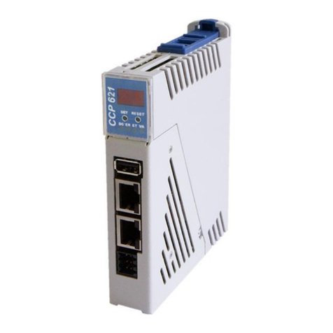
CSCP 012 C-DIAS SAFETY CPU
Page 4 05.10.2018
List of Illustrations
Fig. 1: Minimal system of safety-related control....................................................................7
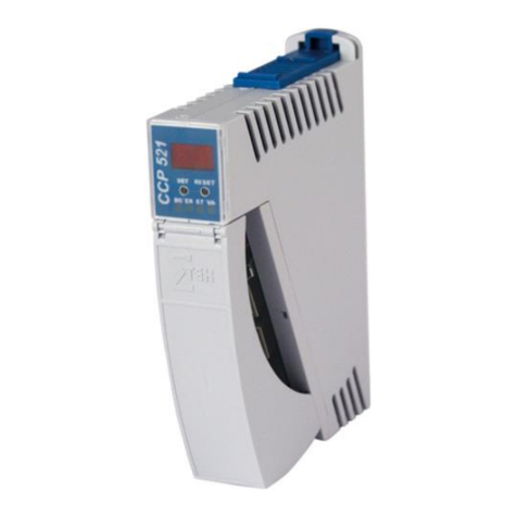
Fig. 2: CSCP 012 ..................................................................................................................9
Fig. 3: Mechanical dimensions............................................................................................11
Fig. 4: Inductive load...........................................................................................................13
Fig. 5: Capacitive load.........................................................................................................13
Fig. 6: CSCP 012 circuit......................................................................................................18
Fig. 7: Connector plug coding.............................................................................................21
Fig. 8: Command sequences..............................................................................................22
Fig. 9: Simplified status diagram.........................................................................................28
Fig. 10: Input circuit structure..............................................................................................31
Fig. 11: Output circuit structure...........................................................................................31
Fig. 12: Simplified representation of the processing machine ............................................32
Fig. 13: Example structure diagram ....................................................................................34
List of Tables
Table 1: C-DIAS bus connector layout..................................................................................7
Table 2: Output specifications.............................................................................................12
Table 3: Allowable output loads ..........................................................................................13
Table 4: Input specifications................................................................................................14
Table 5: Signal output specifications...................................................................................14
Table 6: Electrical requirements..........................................................................................15
Table 7: Safety-relevant parameters...................................................................................16
Table 8: Environmental conditions......................................................................................17
Table 9: LED Display ..........................................................................................................19
Table 10: Connector layout.................................................................................................20
Table 11: Overview of commands.......................................................................................24
Table 12: Module status overview.......................................................................................24
Table 13: Status transitions.................................................................................................25
Table 14: Connection diagram example .............................................................................35
