EVGA Z97 User manual

- 1 -
User Guide
EVGA Z97
Motherboard Installation
(Part 2)

- 2 -
Table of Contents
Installing the Motherboard……………………………………………………3
Installing the I/O Shield/Cover…………………………………………….…3
Securing the Motherboard into a System Case………………………………....4
Connecting Cables…………………………………………………………….6
24pin ATX Power (ATX_PWR_24P)…………………………………………6
8-pin ATX 12V Power (PWR 8P1)……………………………………………7
Connecting Internal Headers………………………………………………….8
Front Panel Header…………………………………………………………...8
USB Headers………………………………………………………………….9
Audio………………………………………………………………………...10
PCI-E x16/x8 Slot…………………………………………………………...10
Onboard Buttons…………………………………………………………….11
Clear CMOS Button…………………………………………………………11
RESET and POWER Button………………………………………………...11
Post Debug LED and LED Status Indicators………………………………..12
Post Port Debug LED……………………………………………………….12
LED Status Indicators……………………………………………………….12
Installing Drivers and Software……………………………………………...13
Windows 8/7 Driver Installation…………………………………………….13
POST Codes…………………………………………………………………14
EVGA Glossary of Terms…………………………………………………...18
Compliance Information …………………………………………………….21

- 3 -
Installing the Motherboard
The sequence of installing the motherboard into a system case depends on the
chassis you are using and if you are replacing an existing motherboard or
working with an empty system case. Determine if it would be easier to make all
the connections prior to this step or to secure the motherboard and then make
all the connections. It is normally easier to secure the motherboard first.
Use the following procedure to install the I/O shield and secure the
motherboard into the chassis.
Note: Be sure that the CPU fan assembly has enough clearance for the system
case covers to lock into place and for the expansion cards. Also make sure
the CPU Fan assembly is aligned with the vents on the covers. This will
depend on the system case being used.
Installing the I/O Shield/Cover
The motherboard kit comes with an I/O shield that is used to block internal
components from dust and foreign objects, and promotes correct airflow within
the chassis.
Before installing the motherboard, install the I/O shield from the inside of the
chassis. Press the I/O shield into place and make sure it fits securely.
Also included is an I/O cover. This I/O cover adds a unique appearance to the
I/O area of the motherboard and is completely optional. If you wish to use the
cover, please place it over the I/O area, and install the chassis screws. The
chassis screws are intended to hold the I/O cover down.

- 4 -
Securing the Motherboard into a System Case
Most system cases have a base with mounting holes you thread standoffs onto to
allow the motherboard to be secured to the chassis and help to prevent short
circuits. If there are studs that do not align with a mounting hole on the
motherboard, it is recommended that you remove that standoff to prevent the
possibility of a short circuit.
Carefully place the motherboard onto the standoffs located inside the
chassis.
Align the mounting holes with the standoffs.
Align the connectors to the I/O shield and/or I/O cover.
Ensure that the fan assembly is aligned with the chassis vents according to
the fan assembly instruction.
Secure the motherboard with four (4), or ten (10) screws depending on the
specific board in the series. Ensure that each screw is lined up with and
screwing into the corresponding standoff under the board. Double check
alignment to make sure nothing gets cross-threaded.
See the picture below for a zoomed in view of a hole to use a standoff in as
well as the locations of standoff holes for all boards in the Z97 series.

- 5 -
Above, all locations safe to secure the board to a standoff with are
circled in red, and the upper left side of that picture is a zoomed in
view of the hole.
Keep in mind that when the screws are installed but not fully tightened,
the motherboard should have 1-2mm of movement, this can help with
getting cards mounted or other tight tolerance/close fitting cards.

- 6 -
Connecting Cables
This section takes you through all the necessary connections on the
motherboard. This will include:
Power Connections
24pin ATX power (PW1)
EPS 8pin 12V power
Internal Headers
Front Panel connectors (power/reset/LED’s)
Fan Headers (PWM for CPU and DC for )
USB 2.0 Header
USB 3.0 Header
Audio Header (FTW and Classified)
SATA III
Rear I/O Panel
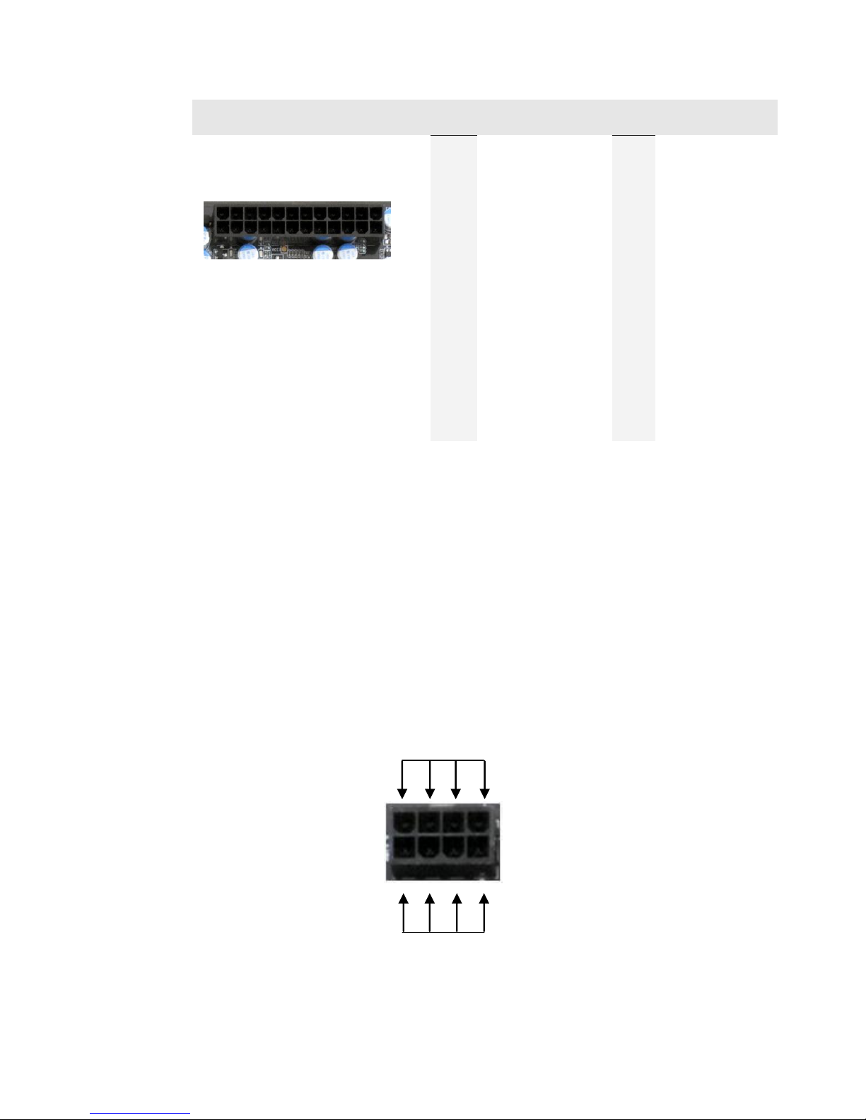
24pin ATX Power (ATX_PWR_24P)
ATX_PWR_24p is the main power supply connector located along the lower
right edge of the board. Make sure that the power supply cable and pins are
properly aligned with the connector on the motherboard. Firmly plug the power
supply cable into the connector and make sure it is secure.
The 24pin Power Connector may be standard or right angled depending on
your motherboard model.
24pin Power Connector
- 7 -
Connector
Pin
Signal
Pin
Signal
1
+3.3V
13
+3.3V
2
+3.3V
14
-12V
3
GND
15
GND
4
+5V
16
PS_ON
5
GND
17
GND
6
+5V
18
GND
7
GND
19
GND
8
PWROK
20
RSVD
9
+5V_AUX
21
+5V
10
+12V
22
+5V
11
+12V
23
+5V
12
+3.3V
24
GND
EPS 8-pin 12V Power (PWR 8P1)
EPS PWR 8P1, the 8-pin ATX 12V power connections, is used to provide
power to the CPU. Align the pins to the connector and press firmly until seated.
The secondary is optional for improved overclocking. Please remember to
make sure that the tab on the EPS socket is aligned with the release clip on the
cable, because if they are on opposite sides, while it will be able to fit, it is the
incorrect cable and may damage the board, as that is a PCI-E 8pin cable.
24
13
12
1
GND
+12V

- 8 -
Connecting Internal Headers
Front Panel Header
The front panel header on this motherboard is used to
connect the following four cables.
PWRLED
Attach the front panel power LED
cable to these two pins of the connector. The Power
LED indicates the system’s status. When the system is
powered on, the LED will be on.
Note: Some system cases may not have all four cables. Be sure to match the
name on the connectors to the corresponding pins.
PWRSW
Attach the power button cable
from the case to these two pins.
Pressing the power button on the
front panel turns the system on and
off rather than using the onboard
button.
HD_LED
Attach the hard disk drive indicator
LED cable to these two pins. The
HDD indicator LED indicates the
activity status of the hard disks.
RESET
Attach the Reset switch cable from
the front panel of the case to these
two pins.
Pin
Signal
HD_LED
1
HD_PWR
3
HD Active
PWRLED
2
PWR LED
4
STBY LED
RESET
5
Ground
7
RST BTN
PWRSW
6
PWR BTN
8
Ground
No Connect
9
+5V
Empty
10
Empty

- 9 -
USB Headers
This motherboard contains
USB 3.0 and 2.0 ports that are
exposed on the rear panel of
the chassis. The motherboard
also contains 10-pin internal
header connectors onboard
that can be used to connect an
optional external bracket
containing up to four (4) USB
2.0 ports. It also has an
internal header connector for
USB 3.0.
Secure the bracket to either the front or rear panel
of your chassis (not all chassis are equipped with
the front panel option).
Connect the two ends of the cables to the USB 2.0
or 3.0 headers on the motherboard.
Connector
Pin
Signal
USB 2.0 Header
Connector
1
5V_DUAL
3
D-
5
D+
7
GND
9
Empty
Pin
Signal
2
5V_DUAL
4
D-
6
D+
8
GND
10
No Connect

- 10 -
Audio
The audio connector supports HD audio standard and provides two kinds of audio
output choices: the Front Audio and the Rear Audio.
PCI-E x16/x8 Slot
This board has a single PCI-E 16x slot. This is specifically for a video card,
however you can place a different card there and use the Intel HD Graphics on the
CPU. When installing a PCI-E Graphics Card, be sure the retention clip snaps and
locks the card into place. If the card is not seated properly, it could cause a short
across the pins. Secure the card’s metal bracket to the chassis back panel with the
screw used to hold the blank cover.
Connector
Pin
Signal
Front Audio Connector
1
PORT1_L
2
AUD_GND
3
PORT1_R
4
PRECENCE_J
5
PORT2_R
6
SENSE1_RETURN
7
SENSE_SEND
8
Empty
9
PORT2_L
10
SENSE2_RETURN
9
7
5
3
1
10
8
6
4
2

- 11 -
Onboard Buttons
These onboard buttons include RESET, POWER and Clear CMOS. These
functions allow you to easily reset the system, turn on/off the system, or clear
the CMOS.
Clear CMOS Button
The motherboard uses the CMOS RAM to
store all the set parameters. The CMOS can be
cleared by pressing the Clear CMOS button
either onboard or on the external I/O Panel.
RESET and POWER Button
These onboard buttons allow you to easily turn on/off the system. These
buttons allow for easy debugging and testing of the system during
troubleshooting situations.
The POWER button with an integrated LED indicates the system’s status.
When the system is powered on, the LED remains a solid red.
The RESET button with an integrated LED indicates the activity status of the
hard disk drives and will flicker accordingly.
Reset
Button
Power
Button
External Clear CMOS Button
- 12 -
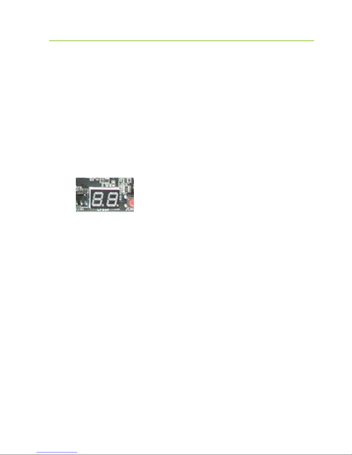
Post Debug LED and LED Status Indicators
Post Port Debug LED
Provides two-digit diagnostic POST codes which shows system boot status and
can also show why the system may be failing to boot. It is very useful during
troubleshooting situations.
This Debug LED will display a series of hexadecimal (0-F) codes during the
POST and upon a successful boot, will display current CPU socket
temperatures after the system has fully booted into the Operating System. See
the “POST CODE” section below for more detailed descriptions of specific
POST Codes.
LED Status Indicators
Theses LEDs indicate the system’s status and are located near the 24pin
connector.
POWER LED (Green):
When the System is powered on: This LED is on.
DIMM LED (Yellow):
When the Memory slot is functional: This LED is on.
STANDBY LED (Blue):
When the System is in Standby Mode: This LED is on. This LED will
remain on as long as the motherboard is receiving constant power.
Debug LED with CPU
Temperature Monitor

- 13 -
Installing Drivers and
Software
Note: It is important to remember that before installing the driver CD that is shipped
in the kit, you need to load your operating system. The motherboard supports
32bit and 64bit versions of Windows 8 or 7.
The kit comes with a CD that contains utilities, drivers, and additional software.
The CD that has been shipped with the EVGA Z97 Motherboard contains the
following software and drivers:
Chipset Drivers
Audio Drivers
RAID Drivers
LAN Drivers
USB 3.0 Drivers
ME Drivers
SATA Drivers
Lucid Drivers
EVGA E-LEET X
User’s Manual
Windows 8/7 Driver Installation
1. Insert the EVGA Z97 installation CD for the motherboard included in the
kit.
2. The CD will autorun. Install the drivers and utilities listed on the install
screen. If the CD does not run, go to My Computer and click on the CD
to open.
- 14 -
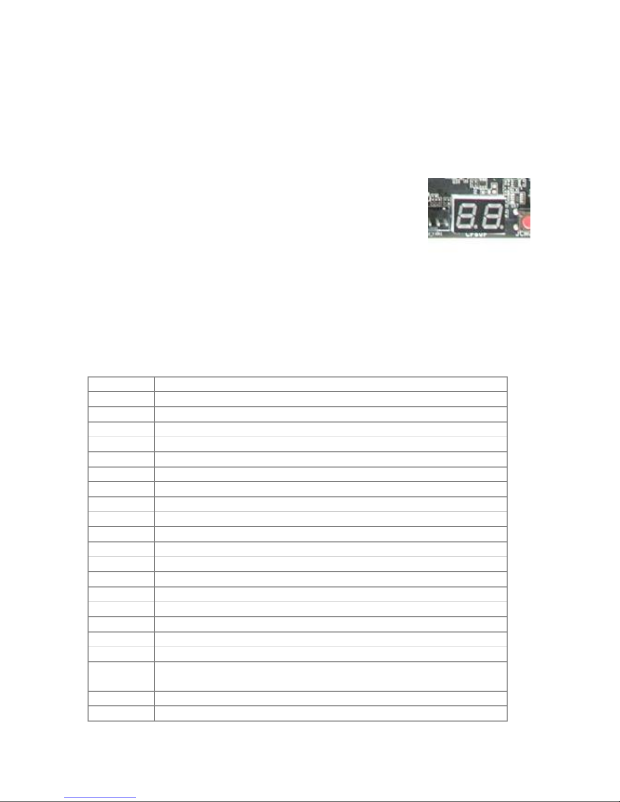
POST Codes
This section provides the AMI POST Codes for the
EVGA Z97 Dark Motherboard during system boot
up.
The POST Codes are displayed on the Debug LED
readout located directly onboard the motherboard.
This Debug LED will also display current CPU
temperatures after the system has fully booted
into the Operating System.
AMI POST Codes
01
Power on. Reset type detection (soft/hard).
02
AP initialization before microcode loading
03
North Bridge initialization before microcode loading
04
South Bridge initialization before microcode loading
05
OEM initialization before microcode loading
06
Microcode loading
07
AP initialization after microcode loading
08
North Bridge initialization after microcode loading
09
South Bridge initialization after microcode loading
0A
OEM initialization after microcode loading
0B
Cache initialization
0C-0D
Reserved for future AMI SEC error codes
0E
Microcode not found
0F
Microcode not loaded
10
PEI Core is started
11-14
Pre-memory CPU initialization is started
15-18
Pre-memory North Bridge initialization is started
19-1C
Pre-memory South Bridge initialization is started
1D-2A
OEM pre-memory initialization codes
2B
Memory initialization. Serial Presence Detect (SPD) data
reading
2C
Memory initialization. Memory presence detection
2D
Memory initialization. Programming memory timing
Debug LED with CPU
Temperature Monitor

- 15 -
information
2E
Memory initialization. Configuring memory
2F
Memory initialization (other).
30
Reserved for ASL (see ASL Status Codes section below)
31
Memory Installed
32
CPU post-memory initialization is started
33
CPU post-memory initialization. Cache initialization
34
CPU post-memory initialization. Application Processor(s) (AP)
initialization
35
CPU post-memory initialization. Boot Strap Processor (BSP)
selection
36
CPU post-memory initialization. System Management Mode
(SMM) initialization
37-3A
Post-Memory North Bridge initialization is started
3B-3E
Post-Memory South Bridge initialization is started
3F-4E
OEM post memory initialization codes
4F
DXE IPL is started
50
Memory initialization error. Invalid memory type or
incompatible memory speed
51
Memory initialization error. SPD reading has failed
52
Memory initialization error. Invalid memory size or memory
modules do not match.
53
Memory initialization error. No usable memory detected
54
Unspecified memory initialization error.
55
Memory not installed
56
Invalid CPU type or Speed
57
CPU mismatch
58
CPU self test failed or possible CPU cache error
59
CPU micro-code is not found or micro-code update is failed
5A
Internal CPU error
5B
reset PPI is not available
5C-5F
Reserved for future AMI error codes
E0
S3 Resume is stared (S3 Resume PPI is called by the DXE
IPL)
E1
S3 Boot Script execution
E2
Video repost
E3
OS S3 wake vector call
E4-E7
Reserved for future AMI progress codes
E8-EB
S3 Resume Failed
EC-EF
Reserved for future AMI error codes
F0
Recovery condition triggered by firmware (Auto recovery)
F1
Recovery condition triggered by user (Forced recovery)
F2
Recovery process started

- 16 -
F3
Recovery firmware image is found
F4
Recovery firmware image is loaded
F5-F7
Reserved for future AMI progress codes
F8
Recovery PPI is not available
F9
Recovery capsule is not found
FA
Invalid recovery capsule
FB–FF
Reserved for future AMI error codes
60
DXE Core is started
61
NVRAM initialization
62
Installation of the South Bridge Runtime Services
63-67
CPU DXE initialization is started
68
PCI host bridge initialization
69
North Bridge DXE initialization is started
6A
North Bridge DXE SMM initialization is started
6B-6F
North Bridge DXE initialization (North Bridge module specific)
70
South Bridge DXE initialization is started
71
South Bridge DXE SMM initialization is started
72
South Bridge devices initialization
73-77
South Bridge DXE Initialization (South Bridge module specific)
78
ACPI module initialization
79
CSM initialization
7A–7F
Reserved for future AMI DXE codes
80–8F
OEM DXE initialization codes
90
Boot Device Selection (BDS) phase is started
91
Driver connecting is started
92
PCI Bus initialization is started
93
PCI Bus Hot Plug Controller Initialization
94
PCI Bus Enumeration
95
PCI Bus Request Resources
96
PCI Bus Assign Resources
97
Console Output devices connect
98
Console input devices connect
99
Super IO Initialization
9A
USB initialization is started
9B
USB Reset
9C
USB Detect
9D
USB Enable
9E–9F
Reserved for future AMI codes
A0
IDE initialization is started
A1
IDE Reset
A2
IDE Detect
A3
IDE Enable
A4
SCSI initialization is started

- 17 -
A5
SCSI Reset
A6
SCSI Detect
A7
SCSI Enable
A8
Setup Verifying Password
A9
Start of Setup
AA
Reserved for ASL (see ASL Status Codes section below)
AB
Setup Input Wait
AC
Reserved for ASL (see ASL Status Codes section below)
AD
Ready To Boot event
AE
Legacy Boot event
AF
Exit Boot Services event
B0
CPU Memory controller configuration
B1
Runtime Set Virtual Address MAP End
B2
iMC init
B3
Memory training
B4
Memory training
B5
Memory training / timing training
B6
Memory training
B7
Memory training
B8-BF
Memory training / DRAM final configuration
C0–CF
OEM BDS initialization codes
D0
CPU initialization error
D1
North Bridge initialization error
D2
South Bridge initialization error
D3
Some of the Architectural Protocols are not available
D4
PCI resource allocation error. Out of Resources
D5
No Space for Legacy Option ROM
D6
No Console Output Devices are found
D7
No Console Input Devices are found
D8
Invalid password
D9
Error loading Boot Option (Load Image returned error)
DA
Boot Option is failed (Start Image returned error)

- 18 -
EVGA Glossary of Terms
AC –Alternating Current
ACPI - Advanced Configuration and Power Interface
AHCI –Advanced Host Controller Interface
AFR –Alternate Frame Rendering
APIC - Advanced Programmable Interrupt Controller
BCLK –Base Clock (or operating frequency of base system bus)
BIOS - Basic Input Output System
CMOS - Complementary Metal-Oxide Semiconductor
CPU –Central Processing Unit
DDR - Double Data Rate
DIMM - Dual In-line Memory Module
DMI –Direct Memory Interface
DRAM - Dynamic random access memory
DVI –Digital Video Interface
ELEET/ELEET X –EVGA motherboard monitoring and tuning software
GHz –Gigahertz
GPU –Graphics Processing Unit
HDD - Hard Disk Drive
HDMI - High-Definition Multimedia Interface
HDR –High Dynamic Range Lighting
HPET - High Precision Event Timer
HT –Hyper-Threading
HSF - Heat Sink Fan
I/O - Input/ Output
IEEE - Institute of Electrical and Electronics Engineers
IGP - Integrated Graphics Processors
IMC –Integrated memory controller

- 19 -
IRQ - Interrupt Request
JBOD - Just a Bunch of Disks
JEDEC - Joint Electron Device Engineering Council
LAN - Local Area Network
LCD - Liquid Crystal Display
LGA –Land Grid Array
LN2 –Liquid Nitrogen Cooling
MAC - Media Access Control
MCP - Media and Communications Processor
Intel ME –Intel Management Engine
MHz –Megahertz
MMIO –Memory Mapped I/O
NB - Northbridge
NCQ - Native Command Queuing
NIC - Network Interface Card
NTFS - New Technology File System
OEM - Original Equipment Manufacturer
PATA - Parallel Advanced Technology Attachment
PCB - Printed Circuit Board
PCH –Platform Controller Hub
PCI - Peripheral Component Interconnect
PCI-E - Peripheral Component Interconnect Express
PLL –Phase Locked Loop
POST –Power on Self Test
PWM –Pulse Width Modulation
QDR - Quad Data Rate
QPI –Quick Path Interconnect
RAID - Redundant Array of Inexpensive Disks
RAM –Random Access Memory
ROM –Read Only Memory
RGB - Red Green Blue

- 20 -
SATA - Serial Advanced Technology Attachment
SAS –Serial Attached SCSI
SB - Southbridge
SCSI - Small Computer System Interface
SFR –Split Frame Rendering
SLI - Scalable Link Interface
SPD - Serial Presence Detect
S/PDIF - Sony/Philips Digital Interconnect Format
SPP - System Platform Processors
SSD –Solid State Drive
TCP/IP - Transmission Control Protocol/Internet Protocol
USB - Universal Serial Bus
VDroop - Voltage Droop
VGA - Video Graphics Array
VREG –Voltage Regulator
Other manuals for Z97
3
Table of contents
Other EVGA Motherboard manuals

EVGA
EVGA Z170 STINGER User manual

EVGA
EVGA nForce 3 250 User manual

EVGA
EVGA X79 Classified User manual

EVGA
EVGA 120-SB-E682-KR User manual

EVGA
EVGA Z97 User manual

EVGA
EVGA 121-BL-E756 User manual

EVGA
EVGA B360 Micro Gaming User manual

EVGA
EVGA Z77 FTW User manual

EVGA
EVGA Z370 FTW User manual

EVGA
EVGA Z97 FTW User manual

EVGA
EVGA nForce 750i SLI User manual

EVGA
EVGA Z97 User manual

EVGA
EVGA X58 SLI LE User manual

EVGA
EVGA X58 SLI CLASSIFIED User manual

EVGA
EVGA nForce 112-CK-NF70 User manual

EVGA
EVGA 160-SB-E679-KR User manual

EVGA
EVGA X58 3X SLI User manual

EVGA
EVGA 141-GT-E770-A1 User manual

EVGA
EVGA X299 Micro User manual

EVGA
EVGA Z370 Classified K User manual


