EVGA Z77 Stinger User manual

User Guide
EVGA Z77 Stinger
Motherboard

EVGA Z77 Stinger Motherboard
2
Table of Contents
User Guide....................................................................................................................1
EVGA Z77 Stinger.........................................................................................................1
Motherboard..................................................................................................................1
Before You Begin… ......................................................................................................4
Parts NOT in the Kit..............................................................................................................4
Intentions of the Kit ..............................................................................................................5
Motherboard..................................................................................................................6
Motherboard Specifications ..................................................................................................6
Unpacking and Parts Descriptions................................................................................7
Unpacking.............................................................................................................................7
Equipment.............................................................................................................................7
Hardware Installation ....................................................................................................9
Safety Instructions.................................................................................................................9
Preparing the Motherboard..................................................................................................10
Installing the CPU...........................................................................................................10
Installing the CPU Fan....................................................................................................11
Installing System Memory (DIMMs) .............................................................................12
Installing the Motherboard..................................................................................................12
Installing the I/O Shield..................................................................................................13
Securing the Motherboard into a System Case ...............................................................14
Connecting Cables ..............................................................................................................14
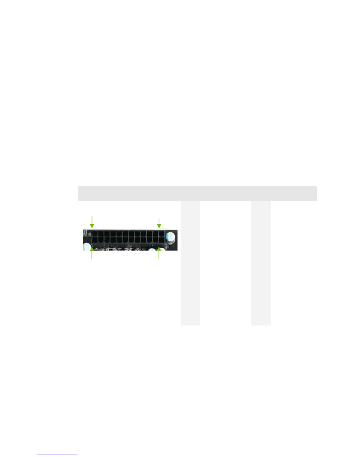
24-pin ATX Power (PWR_24)...................................................................................15
8-pin ATX 12V Power (ATX_PWR_8P)...................................................................16

EVGA Z77 Stinger Motherboard
3
Connecting Internal Headers...........................................................................................16
Front Panel Header.....................................................................................................16
USB Headers..............................................................................................................18
Mini PCI-E Slot..........................................................................................................19
PCI-E x16 Slot............................................................................................................19
Onboard Buttons .................................................................................................................20
Clear CMOS Button ...................................................................................................20
RESET and POWER Button ......................................................................................20
Post Port Debug LED and LED Status Indicators...............................................................21
Post Port Debug LED.................................................................................................21
LED Status Indicators.................................................................................................21
Installing Drivers and Software ..................................................................................22
Windows 8/7/Vista/XP........................................................................................................23
Driver Installation ...............................................................................................................23
Appendix A. POST Codes...........................................................................................23
EVGA Glossary of Terms............................................................................................28
Compliance Information..............................................................................................31

EVGA Z77 Stinger Motherboard
4
Before You Begin…
Thank you for purchasing the EVGA Z77 STINGER Motherboard. This board is
based off of the new Intel Z77 chipset with native support for SATA III/6G and USB
3.0 for the performance you demand, delivered when you need it.
As always this board comes with the added bonus of EVGA’s industry leading 24/7
technical support in case you ever have any issues or questions.
Parts NOT in the Kit
This kit contains all the hardware necessary to install and connect your new
EVGA Z77 STINGER Motherboard. However, it does not contain the
following items that must be purchased separately to make the motherboard
functional.
Intel Socket 1155 Processor
DDR3 System Memory
Socket 1155 CPU cooler for the processor
PCI Express Graphics Card
Power Supply
EVGA assumes you have purchased all the necessary parts needed to allow for
proper system functionality. For a full list of supported CPU’s on this
motherboard, please visit http://www.evga.com/support/motherboard/.

EVGA Z77 Stinger Motherboard
5
Intentions of the Kit
This kit provides you with the motherboard and all connecting cables necessary
to install the motherboard into a PC case. If you are building a PC, you will use
most of the cables provided in the kit. If however, you are replacing a
motherboard, you will not need many of the cables.
When replacing a motherboard in a PC case, you will need to reinstall an
operating system even though the current Hard Disk Drive may already have
one installed.

EVGA Z77 Stinger Motherboard
6
Motherboard
Motherboard Specifications
Size
Mini-ITX form factor of 6.7 inches x 6.7 inches
Microprocessor support
Intel Socket 1155 Processor
Operating systems:
Supports Windows 8/7/Vista/XP 32 and 64 bit
Contains Intel Z77 chipset
System Memory support
Supports Dual channel DDR3-2133+. Officially supports up to 16GBs of
DDR3 memory.
USB 2.0 Ports
Supports hot plug
Supports wake-up from S1 and S3 mode
Supports USB 2.0 protocol up to a 480 Mbps transmission rate
USB 3.0 Ports
Backwards compatible USB 2.0 and USB 1.1 support
Supports transfer speeds up to 5Gbps
SATA ports up to 3.0 Gb/s (300 M/s) data transfer rate
Support for RAID 0, RAID 1
ESATA ports up to 3.0 Gb/s (300 M/s) data transfer rate
SATA ports up to 6.0 Gb/s (600 M/s) data transfer rate
Support for RAID 0 & RAID 1
Onboard LAN
Supports 10/100/1000 Mbit/sec Ethernet

EVGA Z77 Stinger Motherboard
7
Onboard Audio
Realtek High-Definition audio
Supports 8-channel audio
Supports Jack-Sensing function
PCI-E Support
PCI-E 3.0 Slots
Low power consumption and power management features
Green Function
Supports ACPI (Advanced Configuration and Power Interface)
Supports S0 (normal), S1 (power on suspend), S3 (suspend to RAM), S4
(Suspend to disk - depends on OS), and S5 (soft - off)
Expansion Slots
PCI-E x16 slot
Unpacking and
Parts Descriptions
Unpacking
The EVGA Z77 STINGER Motherboard comes with all the necessary cables
for adding a motherboard to a system case. If replacing a motherboard, you may
not need many of these cables.
Equipment
The following accessories are included with the EVGA Z77 STINGER
Motherboard:

EVGA Z77 Stinger Motherboard
8
The EVGA Z77 STINGER Motherboard
This PCI-E motherboard contains the Intel Z77 chipset.
1- Visual Guide
Helps to quickly and visually guide you through the hardware
installation of the motherboard.
1- I/O Shield
Installs in the system case to block radio frequency
transmissions, protect internal components from dust, foreign
objects, and aids in proper airflow within the chassis.
1–SATA II/3G Data Cables
Used to support the SATA protocol and each one connects a
single drive to the motherboard.
1–SATA III/6G Data Cables
Used to support the SATAIII/6G high speed protocol and each
one connects a single drive to the motherboard.
1- Installation CD
Contains drivers that are needed to setup the motherboard.
1–User Manual
Contains Information needed to properly install and configure
your EVGA Motherboard.
1–Screw
Screw in the mPCI-E card to motherboard with the bundle
screw.

EVGA Z77 Stinger Motherboard
9
Hardware Installation
This section will guide you through the installation of the motherboard. The
topics covered in this section are:
Preparing the motherboard
Installing the CPU
Installing the CPU fan
Installing the memory
Installing the motherboard
Connecting cables
Safety Instructions
To reduce the risk of fire, electric shock, and injury, always follow basic
safety precautions.
Remember to remove power from your computer by disconnecting the
AC main source before removing or installing any equipment from/to the
computer chassis.

EVGA Z77 Stinger Motherboard
10
Preparing the Motherboard
Installing the CPU
Be very careful when handling the CPU. Hold
the processor only by the edges and do not
touch the bottom of the processor.
Use the following procedure to install the CPU
onto the motherboard:
Unhook the socket lever by pushing down
and away from the socket.
Pull the socket lever back and the load
plate will automatically lift.
Note: After removing the CPU socket
cover, it is recommended that
you keep it in case you need to
remove the CPU so for any
reason you can replace the
cover to avoid damaging the CPU socket pins.

EVGA Z77 Stinger Motherboard
11
Align the notches in the processor with
the notches on the socket.
Lower the processor straight down into the
socket without tilting or sliding it into
the socket.
Note: Make sure the CPU is fully seated and
level in the socket.
Lower the load so it is resting on the CPU.
Pull back the socket lever again to ensure the
load plate tip engages under the shoulder
screw up and protective cover will be
rejected by installed CPU.
Carefully lock the lever back into place.
The CPU installation is complete.
Installing the CPU Fan
There are many different fan types that can be used with this motherboard.
Follow the instruction that came with your fan assembly. Be sure that the fan
orientation is correct for your chassis type and your fan assembly.
Align notches with notches on the CPU

EVGA Z77 Stinger Motherboard
12
Installing System Memory (DIMMs)
Your new motherboard has two 240-pin slots for DDR3 memory. These slots
support 1GB, 2GB, 4GB and 8GB DDR3 DIMMs. There must be at least one
memory slot populated to ensure normal operation.
Use the following procedure to install DIMMs. Note that there is only one gap
near the center of the DIMM slot. This slot matches the slot on the DIMM to
ensure the component is installed properly.
1. Unlock a DIMM slot by pressing the module clips outward.
Align the memory module to the DIMM slot, and insert the module vertically
into the DIMM slot. The plastic clips at both sides of the DIMM slot
automatically lock the DIMM into the connector.
Installing the Motherboard
The sequence of installing the motherboard into a system case depends on the
chassis you are using and if you are replacing an existing motherboard or
working with an empty system case. Determine if it would be easier to make all
the connections prior to this step or to secure the motherboard and then make
all the connections. It is normally easier to secure the motherboard first.
Use the following procedure to install the I/O shield and secure the
motherboard into the chassis.
Note: Be sure that the CPU fan assembly has enough clearance for the system
case covers to lock into place and for the expansion cards. Also make sure
the CPU Fan assembly is aligned with the vents on the covers. This will
depend on the system case being used.
DIMM 1
DIMM 2

EVGA Z77 Stinger Motherboard
13
Installing the I/O Shield
The motherboard kit comes with an I/O shield that is used to block radio
frequency transmissions, protects internal components from dust and foreign
objects, and promotes correct airflow within the chassis.
Before installing the motherboard, install the I/O shield from the inside of the
chassis. Press the I/O shield into place and make sure it fits securely. If the
I/O shield does not fit into the chassis, you would need to obtain the proper
size from the chassis supplier.
Also Note that for ease of installation you may want to install I/O shield Fan
(optional) before installing into case.

EVGA Z77 Stinger Motherboard
14
Securing the Motherboard into a System Case
Most system cases have a base with mounting studs or spacers to allow the
motherboard to be secured to the chassis and help to prevent short circuits. If
there are studs that do not align with a mounting hole on the motherboard, it is
recommended that you remove that stud to prevent the possibility of a short
circuit. In most cases, it is recommended to secure the motherboard using a
minimum of four (4) spacers and screws.
1. Carefully place the motherboard onto the stand offs located inside the chassis.
2. Align the mounting holes with the stand offs.
3. Align the connectors to the I/O shield.
4. Ensure that the fan assembly is aligned with the chassis vents according to the fan
assembly instruction.
5. Secure the motherboard with a recommended minimum of nine (9) screws.
Connecting Cables
This section takes you through all the necessary connections on the
motherboard. This will include:
Power Connections
24-pin ATX power (ATX_PWR_24)
8-pin ATX 12V power (ATX_PWR_8P)
Internal Headers
Front Panel Header
USB Headers
Audio Header
SATA II
SATA III
Chassis Fans
USB 2.0
USB 3.0

EVGA Z77 Stinger Motherboard
15
Expansion slots
CMOS Clear Button
24-pin ATX Power (PWR_24)
PWR_24 is the main power supply connector located along the edge of the
board next to the DIMM slots. Make sure that the power supply cable and pins
are properly aligned with the connector on the motherboard. Firmly plug the
power supply cable into the connector and make sure it is secure.
Figure 1. PWR_24 Motherboard Connector
Table 1. PWR_24 Pin Assignments
Connector
Pin
Signal
Pin
Signal
1
+3.3V
13
+3.3V
2
+3.3V
14
-12V
3
GND
15
GND
4
+5V
16
PS_ON
5
GND
17
GND
6
+5V
18
GND
7
GND
19
GND
8
PWROK
20
RSVD
9
+5V_AUX
21
+5V
10
+12V
22
+5V
11
+12V
23
+5V
12
+3.3V
24
GND
24
13
12
1

EVGA Z77 Stinger Motherboard
16
8-pin ATX 12V Power (ATX_PWR_8P)
PW1, the 8-pin ATX 12V power connection, is used to provide power to the
CPU. Align the pins to the connector and press firmly until seated.
Connecting Internal Headers
Front Panel Header
The front panel header on this motherboard is one connector used to connect
the following four cables.
(see Table 2 for pin definitions):
PWRLED
Attach the front panel power LED
cable to these two pins of the connector. The Power LED indicates the
system’s status. When the system is powered on, the LED will be on. When
the system is turned off, the LED is off. When the system is in S1, S3,
S4 status, the LED will blink.
+12V
GND

EVGA Z77 Stinger Motherboard
17
Note: Some system cases do not have all four cables. Be sure to match the
name on the connectors to the corresponding pins.
PWRSW
Attach the power button cable from
the case to these two pins. Pressing
the power button on the front panel
turns the system on and off rather
than using the onboard button.
HD_LED
Attach the hard disk drive indicator
LED cable to these two pins. The
HDD indicator LED indicates the
activity status of the hard disks.
RESET
Attach the Reset switch cable from
the front panel of the case to these
two pins. The system restarts when
the RESET switch is pressed.
Table 2.Front Panel Header Pins
Pin
Signal
HD_LED
1
HD_PWR
3
HD Active
PWRLED
2
PWR LED
4
STBY LED
RESET
5
Ground
7
RST BTN
PWRSW
6
PWR BTN
8
Ground
No Connect
9
+5V
Empty
10
Empty

EVGA Z77 Stinger Motherboard
18
USB Headers
This motherboard contains two (2) USB 2.0
ports that are exposed on the rear panel of the
chassis. The motherboard also contains two 10-
pin internal header connectors onboard that can
be used to connect an optional external bracket
containing up to four (4) USB 2.0 ports.
1. Secure the bracket to either the front or rear panel
of your chassis (not all chassis are equipped with the
front panel option).
2. Connect the two ends of the cables to the USB 2.0
headers on the motherboard.
Table 3. USB 2.0 Header Pins
Connector
Pin
Signal
USB 2.0 Header Connector
1
5V_DUAL
3
D-
5
D+
7
GND
9
Empty
Pin
Signal
2
5V_DUAL
4
D-
6
D+
8
GND
10
No Connect

EVGA Z77 Stinger Motherboard
19
Mini PCI-E Slot
There is one Mini PCI-E Slot for use with half-sized Wi-Fi Modules.
PCI-E x16 Slot
This PCI-E slot is reserved for Graphics Cards and PCI-E x1, x4, x8 and x16
devices.
When installing a PCI-E Graphics Card, be sure the retention clip snaps and
locks the card into place. If the card is not seated properly, it could cause a
short across the pins. Secure the card’s metal bracket to the chassis back panel
with the screw used to hold the blank cover.

EVGA Z77 Stinger Motherboard
20
Onboard Buttons
These onboard buttons include RESET, POWER and Clear CMOS. These
functions allow you to easily reset the system, turn on/off the system, or clear
the CMOS.
Clear CMOS Button
The motherboard uses the CMOS
RAM to store all the set parameters.
The CMOS can be cleared by pressing
the Clear CMOS on the external I/O
Panel.
RESET and POWER Button
These onboard buttons allow you to easily turn on/off the system. These
buttons allow for easy debugging and testing of the system during
troubleshooting situations.
The POWER button with an integrated LED indicates the system’s status.
When the system is powered on, the LED remains a solid red.
The RESET button with an integrated LED indicates the activity status of the
hard disk drives and will flicker accordingly.
RESET
Button
POWER
Button
External Clear CMOS Button
Other manuals for Z77 Stinger
1
Table of contents
Other EVGA Motherboard manuals

EVGA
EVGA X79 Classified User manual

EVGA
EVGA Z97 User manual

EVGA
EVGA X58 SLI3 User manual

EVGA
EVGA Z390 FTW User manual

EVGA
EVGA Z75 SLI User manual

EVGA
EVGA X58 SLI3 User manual

EVGA
EVGA X58 SLI 3 System manual

EVGA
EVGA 132-GT-E768 User manual

EVGA
EVGA X79 FTW User manual

EVGA
EVGA X58 Classified3 User manual

EVGA
EVGA X58 SLI CLASSIFIED User manual

EVGA
EVGA Z270 Stinger User manual

EVGA
EVGA P67 FTW User manual

EVGA
EVGA Z68 SLI Micro User manual

EVGA
EVGA P55 FTW 200 System manual

EVGA
EVGA 120-LF-E650-TR User manual

EVGA
EVGA Z490 FTW User manual

EVGA
EVGA H370 Stinger User manual

EVGA
EVGA EVGA X79 DARK System manual

EVGA
EVGA nForce 3 250 User manual