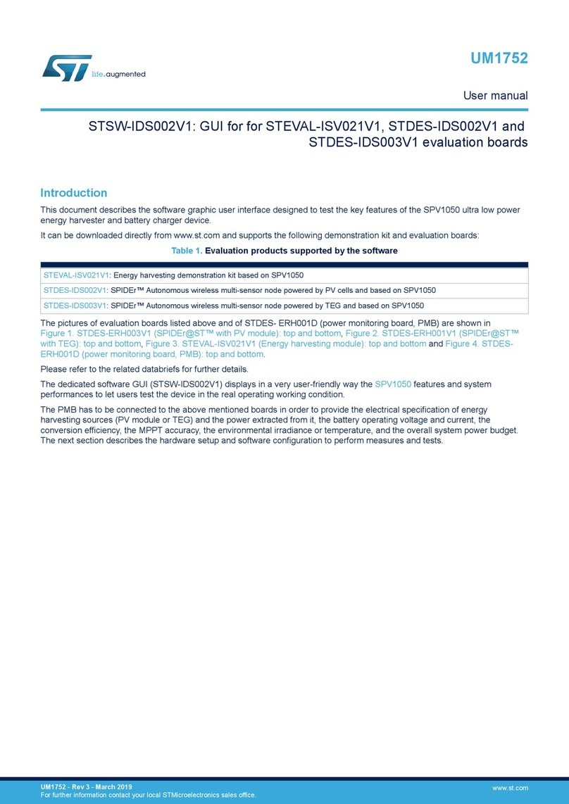
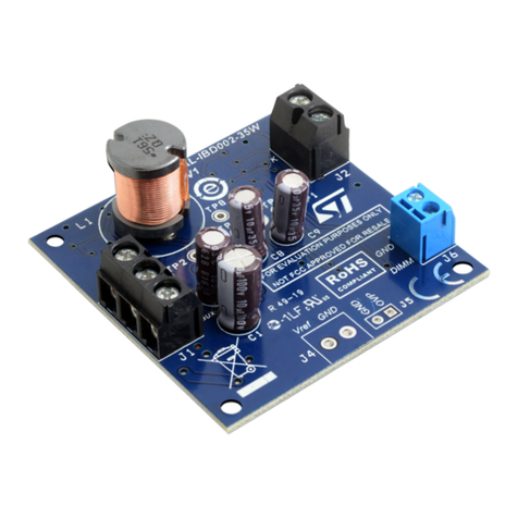
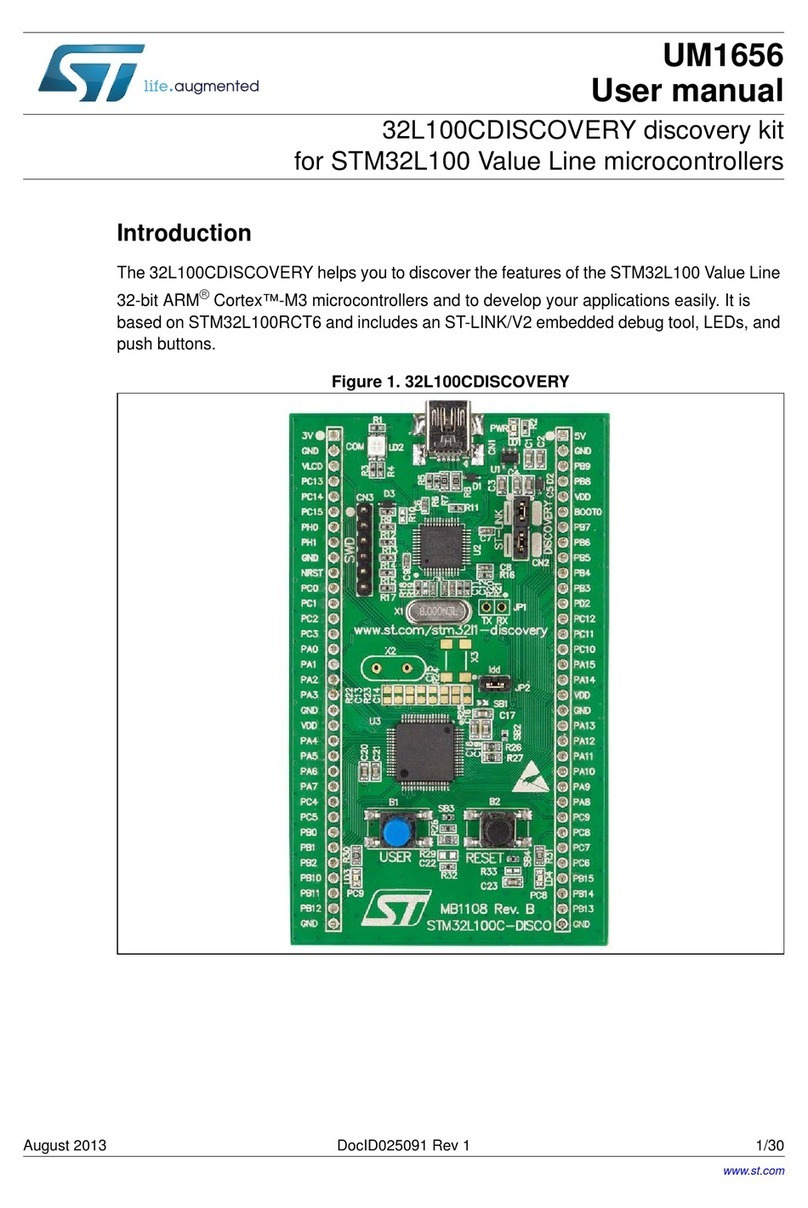
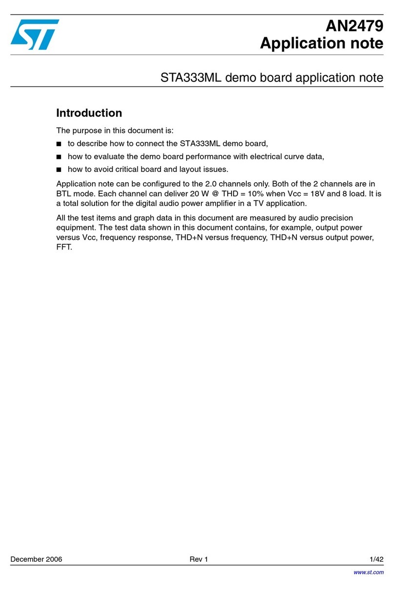
ST UM1461 User manual

April 2012 Doc ID 022138 Rev 4 1/67
UM1461
User manual
STM3240G-EVAL evaluation board
Introduction
The STM3240G-EVAL evaluation board is a complete demonstration and development
platform for the STM32F4 series and includes an embedded STM32F407IGH6 high-
performance ARM®Cortex™-M4F 32-bit microcontroller.
The full range of hardware features on the board is provided to help you evaluate all
peripherals (USB-OTG HS, USB-OTG FS, Ethernet, motor control, CAN, MicroSD Card™,
smartcard, USART, Audio DAC, RS-232, IrDA, SRAM, MEMS, EEPROM… etc.) and
develop your own applications. Extension headers make it possible to easily connect a
daughterboard or wrapping board for your specific application.
The in-circuit ST-LINK/V2 tool can be easily used for JTAG and SWD interface debugging
and programming.
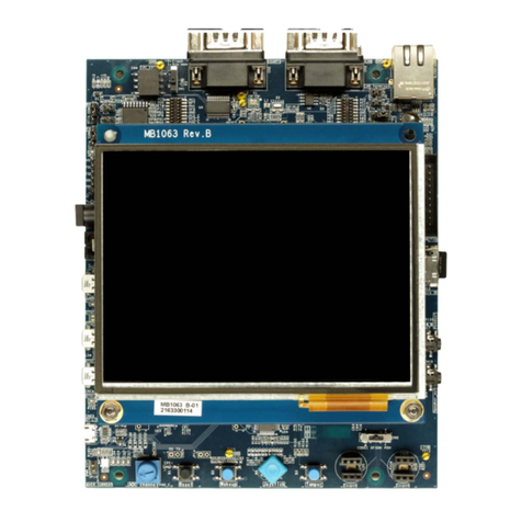
Figure 1. STM3240G-EVAL evaluation board
www.st.com

Contents UM1461
2/67 Doc ID 022138 Rev 4
Contents
1 Overview . . . . . . . . . . . . . . . . . . . . . . . . . . . . . . . . . . . . . . . . . . . . . . . . . . 6
1.1 Features . . . . . . . . . . . . . . . . . . . . . . . . . . . . . . . . . . . . . . . . . . . . . . . . . . . 6
1.2 Demonstration software . . . . . . . . . . . . . . . . . . . . . . . . . . . . . . . . . . . . . . . 6
1.3 Order code . . . . . . . . . . . . . . . . . . . . . . . . . . . . . . . . . . . . . . . . . . . . . . . . . 6
1.4 Delivery recommendations . . . . . . . . . . . . . . . . . . . . . . . . . . . . . . . . . . . . . 7
2 Hardware layout and configuration . . . . . . . . . . . . . . . . . . . . . . . . . . . . . 8
2.1 Power supply . . . . . . . . . . . . . . . . . . . . . . . . . . . . . . . . . . . . . . . . . . . . . . 11
2.2 Boot option . . . . . . . . . . . . . . . . . . . . . . . . . . . . . . . . . . . . . . . . . . . . . . . . 12
2.3 Clock source . . . . . . . . . . . . . . . . . . . . . . . . . . . . . . . . . . . . . . . . . . . . . . . 13
2.4 Reset source . . . . . . . . . . . . . . . . . . . . . . . . . . . . . . . . . . . . . . . . . . . . . . 13
2.5 Audio . . . . . . . . . . . . . . . . . . . . . . . . . . . . . . . . . . . . . . . . . . . . . . . . . . . . 13
2.6 EEPROM . . . . . . . . . . . . . . . . . . . . . . . . . . . . . . . . . . . . . . . . . . . . . . . . . 14
2.7 CAN . . . . . . . . . . . . . . . . . . . . . . . . . . . . . . . . . . . . . . . . . . . . . . . . . . . . . 14
2.8 RS-232 and IrDA . . . . . . . . . . . . . . . . . . . . . . . . . . . . . . . . . . . . . . . . . . . 15
2.9 Motor control . . . . . . . . . . . . . . . . . . . . . . . . . . . . . . . . . . . . . . . . . . . . . . 16
2.10 Smartcard . . . . . . . . . . . . . . . . . . . . . . . . . . . . . . . . . . . . . . . . . . . . . . . . . 17
2.11 MicroSD Card . . . . . . . . . . . . . . . . . . . . . . . . . . . . . . . . . . . . . . . . . . . . . . 17
2.12 MEMS . . . . . . . . . . . . . . . . . . . . . . . . . . . . . . . . . . . . . . . . . . . . . . . . . . . . 18
2.13 Potentiometer . . . . . . . . . . . . . . . . . . . . . . . . . . . . . . . . . . . . . . . . . . . . . . 18
2.14 ADC . . . . . . . . . . . . . . . . . . . . . . . . . . . . . . . . . . . . . . . . . . . . . . . . . . . . . 18
2.15 USB-OTG FS . . . . . . . . . . . . . . . . . . . . . . . . . . . . . . . . . . . . . . . . . . . . . . 18
2.16 Ethernet . . . . . . . . . . . . . . . . . . . . . . . . . . . . . . . . . . . . . . . . . . . . . . . . . . 18
2.17 USB-OTG HS . . . . . . . . . . . . . . . . . . . . . . . . . . . . . . . . . . . . . . . . . . . . . . 19
2.18 Camera module . . . . . . . . . . . . . . . . . . . . . . . . . . . . . . . . . . . . . . . . . . . . 20
2.19 SRAM . . . . . . . . . . . . . . . . . . . . . . . . . . . . . . . . . . . . . . . . . . . . . . . . . . . . 21
2.20 Development and debug support . . . . . . . . . . . . . . . . . . . . . . . . . . . . . . . 21
2.21 Display and input devices . . . . . . . . . . . . . . . . . . . . . . . . . . . . . . . . . . . . . 23
3 Connectors . . . . . . . . . . . . . . . . . . . . . . . . . . . . . . . . . . . . . . . . . . . . . . . 24
3.1 Daughterboard extension connectors CN1, 2, 3 and 4 . . . . . . . . . . . . . . 24

UM1461 Contents
Doc ID 022138 Rev 4 3/67
3.2 Motor control connector CN5 . . . . . . . . . . . . . . . . . . . . . . . . . . . . . . . . . . 31
3.3 MicroSD connector CN6 . . . . . . . . . . . . . . . . . . . . . . . . . . . . . . . . . . . . . . 32
3.4 Ethernet RJ45 connector CN7 . . . . . . . . . . . . . . . . . . . . . . . . . . . . . . . . . 32
3.5 USB-OTG FS Micro-AB connector CN8 . . . . . . . . . . . . . . . . . . . . . . . . . . 33
3.6 USB-OTG HS Micro-AB connector CN9 . . . . . . . . . . . . . . . . . . . . . . . . . 33
3.7 CAN D-type 9-pin male connectors CN10 (CAN1 or CAN2) . . . . . . . . . . 34
3.8 Audio connector CN11 . . . . . . . . . . . . . . . . . . . . . . . . . . . . . . . . . . . . . . . 34
3.9 Trace debugging connector CN13 . . . . . . . . . . . . . . . . . . . . . . . . . . . . . . 34
3.10 JTAG debugging connector CN14 . . . . . . . . . . . . . . . . . . . . . . . . . . . . . . 35
3.11 Camera module connector CN15 . . . . . . . . . . . . . . . . . . . . . . . . . . . . . . . 35
3.12 RS-232 connector CN16 . . . . . . . . . . . . . . . . . . . . . . . . . . . . . . . . . . . . . 36
3.13 Power connector CN18 . . . . . . . . . . . . . . . . . . . . . . . . . . . . . . . . . . . . . . 36
3.14 TFT LCD connector CN19 . . . . . . . . . . . . . . . . . . . . . . . . . . . . . . . . . . . . 37
3.15 Smartcard connector CN20 . . . . . . . . . . . . . . . . . . . . . . . . . . . . . . . . . . . 37
3.16 ST-LINK/V2 connector CN21 . . . . . . . . . . . . . . . . . . . . . . . . . . . . . . . . . . 37
3.17 Camera extension connector CN23 . . . . . . . . . . . . . . . . . . . . . . . . . . . . . 38
3.18 STM3240G-EVAL pinout . . . . . . . . . . . . . . . . . . . . . . . . . . . . . . . . . . . . . 38
4 Schematics . . . . . . . . . . . . . . . . . . . . . . . . . . . . . . . . . . . . . . . . . . . . . . . 44
5 Revision history . . . . . . . . . . . . . . . . . . . . . . . . . . . . . . . . . . . . . . . . . . . 66

List of tables UM1461
4/67 Doc ID 022138 Rev 4
List of tables
Table 1. Power related jumpers and solder bridges . . . . . . . . . . . . . . . . . . . . . . . . . . . . . . . . . . . . . 11
Table 2. Boot related jumpers. . . . . . . . . . . . . . . . . . . . . . . . . . . . . . . . . . . . . . . . . . . . . . . . . . . . . . 12
Table 3. Audio related jumpers . . . . . . . . . . . . . . . . . . . . . . . . . . . . . . . . . . . . . . . . . . . . . . . . . . . . . 13
Table 4. EEPROM related jumper and solder bridge . . . . . . . . . . . . . . . . . . . . . . . . . . . . . . . . . . . . 14
Table 5. CAN-related jumpers . . . . . . . . . . . . . . . . . . . . . . . . . . . . . . . . . . . . . . . . . . . . . . . . . . . . . 14
Table 6. RS-232 and IrDA related jumper . . . . . . . . . . . . . . . . . . . . . . . . . . . . . . . . . . . . . . . . . . . . 15
Table 7. Motor control solder bridges . . . . . . . . . . . . . . . . . . . . . . . . . . . . . . . . . . . . . . . . . . . . . . . . 16
Table 8. Connection between ST8024 and STM32F407IGH6 . . . . . . . . . . . . . . . . . . . . . . . . . . . . . 17
Table 9. Smartcard related jumper . . . . . . . . . . . . . . . . . . . . . . . . . . . . . . . . . . . . . . . . . . . . . . . . . . 17
Table 10. MicroSD Card related jumpers . . . . . . . . . . . . . . . . . . . . . . . . . . . . . . . . . . . . . . . . . . . . . . 17
Table 11. Ethernet related jumpers and solder bridges . . . . . . . . . . . . . . . . . . . . . . . . . . . . . . . . . . . 18
Table 12. MicroSD Card related jumper . . . . . . . . . . . . . . . . . . . . . . . . . . . . . . . . . . . . . . . . . . . . . . . 19
Table 13. Camera module related jumpers . . . . . . . . . . . . . . . . . . . . . . . . . . . . . . . . . . . . . . . . . . . . 20
Table 14. SRAM related jumpers . . . . . . . . . . . . . . . . . . . . . . . . . . . . . . . . . . . . . . . . . . . . . . . . . . . . 21
Table 15. Third-party toolchain support . . . . . . . . . . . . . . . . . . . . . . . . . . . . . . . . . . . . . . . . . . . . . . . 21
Table 16. LCD modules . . . . . . . . . . . . . . . . . . . . . . . . . . . . . . . . . . . . . . . . . . . . . . . . . . . . . . . . . . . 23
Table 17. Daughterboard extension connector CN1 . . . . . . . . . . . . . . . . . . . . . . . . . . . . . . . . . . . . . 24
Table 18. Daughterboard extension connector CN2 . . . . . . . . . . . . . . . . . . . . . . . . . . . . . . . . . . . . . 26
Table 19. Daughterboard extension connector CN3 . . . . . . . . . . . . . . . . . . . . . . . . . . . . . . . . . . . . . 27
Table 20. Daughterboard extension connector CN4 . . . . . . . . . . . . . . . . . . . . . . . . . . . . . . . . . . . . . 29
Table 21. Motor control connector CN5 . . . . . . . . . . . . . . . . . . . . . . . . . . . . . . . . . . . . . . . . . . . . . . . 31
Table 22. MicroSD connector CN6 . . . . . . . . . . . . . . . . . . . . . . . . . . . . . . . . . . . . . . . . . . . . . . . . . . . 32
Table 23. RJ45 connector CN7 . . . . . . . . . . . . . . . . . . . . . . . . . . . . . . . . . . . . . . . . . . . . . . . . . . . . . 32
Table 24. USB-OTG FS Micro-AB connector CN8 . . . . . . . . . . . . . . . . . . . . . . . . . . . . . . . . . . . . . . . 33
Table 25. USB-OTG HS Micro-AB connector CN9. . . . . . . . . . . . . . . . . . . . . . . . . . . . . . . . . . . . . . . 33
Table 26. CAN D-type 9-pin male connector CN10 (CAN1 or CAN2) . . . . . . . . . . . . . . . . . . . . . . . . 34
Table 27. Trace debugging connector CN13 . . . . . . . . . . . . . . . . . . . . . . . . . . . . . . . . . . . . . . . . . . . 34
Table 28. JTAG debugging connector CN14 . . . . . . . . . . . . . . . . . . . . . . . . . . . . . . . . . . . . . . . . . . . 35
Table 29. Camera module connector CN15 . . . . . . . . . . . . . . . . . . . . . . . . . . . . . . . . . . . . . . . . . . . . 35
Table 30. RS-232 connector CN16 with ISP support . . . . . . . . . . . . . . . . . . . . . . . . . . . . . . . . . . . . . 36
Table 31. Smartcard connector CN20 . . . . . . . . . . . . . . . . . . . . . . . . . . . . . . . . . . . . . . . . . . . . . . . . 37
Table 32. Camera extension connector CN23 . . . . . . . . . . . . . . . . . . . . . . . . . . . . . . . . . . . . . . . . . . 38
Table 33. STM3240G-EVAL pinout . . . . . . . . . . . . . . . . . . . . . . . . . . . . . . . . . . . . . . . . . . . . . . . . . . 38
Table 34. Document revision history . . . . . . . . . . . . . . . . . . . . . . . . . . . . . . . . . . . . . . . . . . . . . . . . . 66

UM1461 List of figures
Doc ID 022138 Rev 4 5/67
List of figures
Figure 1. STM3240G-EVAL evaluation board . . . . . . . . . . . . . . . . . . . . . . . . . . . . . . . . . . . . . . . . . . . 1
Figure 2. Hardware layout and configuration . . . . . . . . . . . . . . . . . . . . . . . . . . . . . . . . . . . . . . . . . . . . 9
Figure 3. STM3240G-EVAL evaluation board layout . . . . . . . . . . . . . . . . . . . . . . . . . . . . . . . . . . . . . 10
Figure 4. Hardware layout and configuration . . . . . . . . . . . . . . . . . . . . . . . . . . . . . . . . . . . . . . . . . . . 10
Figure 5. STM3240G-EVAL evaluation board layout . . . . . . . . . . . . . . . . . . . . . . . . . . . . . . . . . . . . . 10
Figure 6. Pin 1 camera plug. . . . . . . . . . . . . . . . . . . . . . . . . . . . . . . . . . . . . . . . . . . . . . . . . . . . . . . . 20
Figure 7. Motor control connector CN5 . . . . . . . . . . . . . . . . . . . . . . . . . . . . . . . . . . . . . . . . . . . . . . . 31
Figure 8. MicroSD connector CN6 . . . . . . . . . . . . . . . . . . . . . . . . . . . . . . . . . . . . . . . . . . . . . . . . . . . 32
Figure 9. Ethernet RJ45 connector CN7 . . . . . . . . . . . . . . . . . . . . . . . . . . . . . . . . . . . . . . . . . . . . . . 32
Figure 10. USB-OTG FS Micro-AB connector CN8 . . . . . . . . . . . . . . . . . . . . . . . . . . . . . . . . . . . . . . . 33
Figure 11. USB-OTG HS Micro-AB connector CN9 . . . . . . . . . . . . . . . . . . . . . . . . . . . . . . . . . . . . . . 33
Figure 12. CAN D-type 9-pin male connector CN10 (CAN1 or CAN2) . . . . . . . . . . . . . . . . . . . . . . . . 34
Figure 13. Trace debugging connector CN13 . . . . . . . . . . . . . . . . . . . . . . . . . . . . . . . . . . . . . . . . . . . 34
Figure 14. JTAG debugging connector CN14 . . . . . . . . . . . . . . . . . . . . . . . . . . . . . . . . . . . . . . . . . . . 35
Figure 15. Camera module connector CN15 (front view). . . . . . . . . . . . . . . . . . . . . . . . . . . . . . . . . . . 35
Figure 16. RS-232 connector CN16 with ISP support (front view). . . . . . . . . . . . . . . . . . . . . . . . . . . . 36
Figure 17. Power supply connector CN18 . . . . . . . . . . . . . . . . . . . . . . . . . . . . . . . . . . . . . . . . . . . . . . 36
Figure 18. Smartcard connector CN20 . . . . . . . . . . . . . . . . . . . . . . . . . . . . . . . . . . . . . . . . . . . . . . . . 37
Figure 19. STM3240G-EVAL . . . . . . . . . . . . . . . . . . . . . . . . . . . . . . . . . . . . . . . . . . . . . . . . . . . . . . . . 45
Figure 20. MCU . . . . . . . . . . . . . . . . . . . . . . . . . . . . . . . . . . . . . . . . . . . . . . . . . . . . . . . . . . . . . . . . . . 46
Figure 21. USB-OTG HS . . . . . . . . . . . . . . . . . . . . . . . . . . . . . . . . . . . . . . . . . . . . . . . . . . . . . . . . . . . 47
Figure 22. Camera . . . . . . . . . . . . . . . . . . . . . . . . . . . . . . . . . . . . . . . . . . . . . . . . . . . . . . . . . . . . . . . . 48
Figure 23. Ethernet . . . . . . . . . . . . . . . . . . . . . . . . . . . . . . . . . . . . . . . . . . . . . . . . . . . . . . . . . . . . . . . 49
Figure 24. Audio . . . . . . . . . . . . . . . . . . . . . . . . . . . . . . . . . . . . . . . . . . . . . . . . . . . . . . . . . . . . . . . . . 50
Figure 25. USB-OTG FS . . . . . . . . . . . . . . . . . . . . . . . . . . . . . . . . . . . . . . . . . . . . . . . . . . . . . . . . . . . 51
Figure 26. SRAM . . . . . . . . . . . . . . . . . . . . . . . . . . . . . . . . . . . . . . . . . . . . . . . . . . . . . . . . . . . . . . . . 52
Figure 27. LCD . . . . . . . . . . . . . . . . . . . . . . . . . . . . . . . . . . . . . . . . . . . . . . . . . . . . . . . . . . . . . . . . . . 53
Figure 28. RS-232 and IrDA . . . . . . . . . . . . . . . . . . . . . . . . . . . . . . . . . . . . . . . . . . . . . . . . . . . . . . . . 54
Figure 29. CAN . . . . . . . . . . . . . . . . . . . . . . . . . . . . . . . . . . . . . . . . . . . . . . . . . . . . . . . . . . . . . . . . . . 55
Figure 30. I/O peripherals . . . . . . . . . . . . . . . . . . . . . . . . . . . . . . . . . . . . . . . . . . . . . . . . . . . . . . . . . . 56
Figure 31. I/O expandor . . . . . . . . . . . . . . . . . . . . . . . . . . . . . . . . . . . . . . . . . . . . . . . . . . . . . . . . . . . . 57
Figure 32. MicroSD Card . . . . . . . . . . . . . . . . . . . . . . . . . . . . . . . . . . . . . . . . . . . . . . . . . . . . . . . . . . . 58
Figure 33. Motor control . . . . . . . . . . . . . . . . . . . . . . . . . . . . . . . . . . . . . . . . . . . . . . . . . . . . . . . . . . . 59
Figure 34. Smartcard . . . . . . . . . . . . . . . . . . . . . . . . . . . . . . . . . . . . . . . . . . . . . . . . . . . . . . . . . . . . . . 60
Figure 35. JTAG and Trace . . . . . . . . . . . . . . . . . . . . . . . . . . . . . . . . . . . . . . . . . . . . . . . . . . . . . . . . . 61
Figure 36. Power . . . . . . . . . . . . . . . . . . . . . . . . . . . . . . . . . . . . . . . . . . . . . . . . . . . . . . . . . . . . . . . . . 62
Figure 37. Extension connector . . . . . . . . . . . . . . . . . . . . . . . . . . . . . . . . . . . . . . . . . . . . . . . . . . . . . . 63
Figure 38. STLINK/V2 . . . . . . . . . . . . . . . . . . . . . . . . . . . . . . . . . . . . . . . . . . . . . . . . . . . . . . . . . . . . . 64
Figure 39. 3.2” LCD module with SPI and 16-bit interface. . . . . . . . . . . . . . . . . . . . . . . . . . . . . . . . . . 65

Overview UM1461
6/67 Doc ID 022138 Rev 4
1 Overview
1.1 Features
●STM32F407IGH6 microcontroller.
●16 Mbit SRAM
●1 Gbyte or more MicroSD Card
●Boot from user Flash, system memory or SRAM
●Both ISO/IEC 14443 type A and B smartcard support
●I2C compatible serial interface 8 Kbytes EEPROM, MEMS and I/O expander
●IEEE 802.3-2002 compliant Ethernet connector
●Two CAN 2.0 A/B channels on the same DB connector
●RS-232 communication
●IrDA transceiver
●USB-OTG (HS and FS) with Micro-AB connector
●Inductor motor control connector
●I2S Audio DAC, stereo audio jack for headset
●3.2" 240x320 TFT color LCD with touchscreen
●4 color LEDs
●Camera module and extension connector for ST camera plug-in
●Joystick with 4-direction control and selector
●Reset, wakeup, tamper and user button
●RTC with backup battery
●Extension connector for daughterboard or wrapping board
●JTAG, SWD and trace debug support
●Embedded ST-LINK/V2
●Five 5 V power supply options: Power jack, USB FS connector, USB HS connector,
ST-LINK/V2 or daughterboard
1.2 Demonstration software
Demonstration software is preloaded in the board's Flash memory for easy demonstration of
the device peripherals in standalone mode. For more information and to download the latest
version, please refer to STM3240G-EVAL demonstration software available on web:
www.st.com/mcu
1.3 Order code
To order the STM32F407IGH6 MCU evaluation board, use order code STM3240G-EVAL.

UM1461 Overview
Doc ID 022138 Rev 4 7/67
1.4 Delivery recommendations
Several verifications are needed before using the board for the first time to make sure that
nothing has been damaged during shipment and no components are unplugged and lost.
When the board is extracted from its plastic bag, please check that no component remains
in the bag. Main components to verify are:
1. The 25 MHz crystals (X1 and X4) may have been removed by a shock.
2. The camera connected on socket CN15 located on the right side of the board under the
JTAG connector may be unplugged. If this is the case, please refer to the note in
Section 2.18: Camera module to make sure to plug it in the correct position.
3. The MicroSD Card may have been ejected from its connector CN6 (top left corner of
the board).
The plastic protection on the camera should be removed carefully as the connection is very
fragile.

Hardware layout and configuration UM1461
8/67 Doc ID 022138 Rev 4
2 Hardware layout and configuration
The STM3240G-EVAL evaluation board is designed around the STM32F407IGH6 in the
UFBGA176 package. The hardware block diagram Figure 4 illustrates the connection
between the STM32F407IGH6 and the peripherals (camera module, LCD, SRAM,
EEPROM, MEMS, USART, IrDA, USB-OTG HS, USB OTG FS, Ethernet, Audio, CAN bus,
smartcard, MicroSD Card and motor control) and Figure 5 will help you locate these
features on the actual evaluation board.

UM1461 Hardware layout and configuration
Doc ID 022138 Rev 4 9/67
Figure 2. Hardware layout and configuration

Hardware layout and configuration UM1461
10/67 Doc ID 022138 Rev 4
Figure 3. STM3240G-EVAL evaluation board layout
CONNECTOR $4"

UM1461 Hardware layout and configuration
Doc ID 022138 Rev 4 11/67
2.1 Power supply
The STM3240G-EVAL evaluation board is designed to be powered by 5 V DC power supply
and to be protected by PolyZen from a wrong power plug-in event. It is possible to configure
the evaluation board to use any of following five sources for the power supply:
●5 V DC power adapter connected to CN18, the power jack on the board
●5 V DC power with 500 mA limitation from CN8, the USB-OTG FS Micro-AB connector
●5 V DC power with 500 mA limitation from CN9, the USB-OTG HS Micro-AB connector
●5 V DC power with 500 mA limitation from CN21, the ST-LINK/V2 USB connector
●5 V DC power from both CN1 and CN3, the extension connector for daughterboard
(DTB for daughterboard on silkscreen)
The power supply is configured by setting the related jumpers JP4, JP32, JP18 and JP19 as
described inTa b l e 1.
Table 1. Power related jumpers and solder bridges
Jumper Description
JP4
JP4 should be fitted to enable power down reset (PDR). PDR is disabled when JP4
is not fitted.
Default setting: Fitted.
JP32
MCU_VDD is connected to 3.3V power when JP32 is closed and MCU current
consumption measurement can be done manually by multi-meter when JP32 is
open.
Default setting: Fitted.
JP18
JP18 is used to select one of the five possible power supply sources.
To select the ST-LINK/V2 USB connector (CN21) power
supply, set JP18 as shown:
(Default setting)
To s e l e c t power supply jack (CN18) power supply, set
JP18 as shown:
To s e l e c t daughterboard connector (CN1 and CN3)power
supply, set JP18 as shown:
HS
FS
DTB
PSU
STlk
HS
FS
DTB
PSU
STlk
HS
FS
DTB
PSU
STlk

Hardware layout and configuration UM1461
12/67 Doc ID 022138 Rev 4
Note: The LED LD9 is lit when the STM3240G-EVAL evaluation board is powered by the 5V
correctly.
2.2 Boot option
The STM3240G-EVAL evaluation board is able to boot from:
●Embedded user Flash
●System memory with boot loader for ISP
●Embedded SRAM for debugging
The boot option is configured by setting switches SW1 (BOOT1) and SW2 (BOOT0).
BOOT0 can also be configured via RS-232 connector CN16.
JP18
(cont.)
To s e l e c t USB-OTG FS (CN8) power supply, set JP18 as
shown:
To s e l e c t USB-OTG HS (CN9)power supply, set JP18 as
shown:
To s e l e c t power supply jack (CN18) power supply to both
STM3240G-EVAL and daughterboard connected on CN1
and CN3, set JP18 as shown (daughterboard must not
have its own power supply connected)
JP19
To connect Vbat to the battery, set JP19 as shown:
To connect Vbat to 3.3V power, set JP19 as shown:
(Default setting)
Table 1. Power related jumpers and solder bridges (continued)
Jumper Description
HS
FS
DTB
PSU
STlk
HS
FS
DTB
PSU
STlk
HS
FS
DTB
PSU
STlk
321
321
Table 2. Boot related jumpers
BOOT 0 BOOT 1 Boot source
0Don’t care STM3240G-EVAL boots from User Flash (Default setting)
1 1 STM3240G-EVAL boots from Embedded SRAM
1 0 STM3240G-EVAL boots from System Memory

UM1461 Hardware layout and configuration
Doc ID 022138 Rev 4 13/67
2.3 Clock source
Four clock sources are available on the STM3240G-EVAL evaluation board for
STM32F407IGH6 and RTC embedded:
●X1, 25 MHz crystal for Ethernet PHY with socket. It can be removed when clock is
provided by the MCU MCO pin
●X2, 26 MHz crystal for USB-OTG HS PHY
●X3, 32 kHz crystal for embedded RTC
●X4, 25 MHz crystal with socket for the,STM32F407IGH6 microcontroller (it can be
removed from socket when internal RC clock is used)
2.4 Reset source
The reset signal of the STM3240G-EVAL evaluation board is low active and the reset
sources include:
●Reset button B1
●Debugging tools from JTAG connector CN14 and trace connector CN13
●Daughterboard from CN3
●RS-232 connector CN916 for ISP
●ST-LINK/V2
2.5 Audio
The STM3240G-EVAL evaluation board enables stereo audio play and microphone
recording by an external headset connected on audio jack CN11. An audio DAC CS43L22 is
connected to both I2S2 port and a DAC channel and a microphone amplifier is connected to
the ADC of the STM32F407IGH6. CS43L22 can be configured via I2C1 and the external
PLL (U36) can be used to provide external clock which is connected to I2S_CKIN pin (PC9).
Note: To avoid speaker damage it is mandatory to connect the headphone to the board on CN11
during debug of audio code. When the program is stopped on a breakpoint, a DC voltage
may be applied to the speaker which induces power consumption incompatible with the
speaker.
Warning: Signal I2S_SD (PI3) is close to signal TCK/SWCLK of the
JTAG/SWD interface, so to avoid possible communication
issues on JTAG/SWD when the I2S interface is used the
recommendations are to:
1) Prefer usage of embedded ST-LINK/V2 to external tool
connected on CN14.
2) Configure PI3 GPIO in low speed (2 MHz or 10 MHz).
Table 3. Audio related jumpers
Jumper Description
JP16 Description of JP16 is in Ta bl e 10 on page 17.
JP33 The microphone amplifier can be disabled when JP33 is fitted.Default setting: Not fitted

Hardware layout and configuration UM1461
14/67 Doc ID 022138 Rev 4
2.6 EEPROM
A 64 Kbit EEPROM is connected to the I2C1 bus of the STM32F407IGH6.
2.7 CAN
The STM3240G-EVAL evaluation board enables two channels of CAN2.0A/B compliant
CAN bus communication based on a 3.3V CAN transceiver on one DB9 connector (CN10).
The two CAN buses can be disconnected by jumpers from relevant STM32F407IGH6 I/Os
which are shared with FSMC and USB-OTG HS. Jumpers JP3 and JP10 must be refit to
enable CAN1 or CAN2 as listed in Ta b l e 5.
High-speed, Standby and Slope Control modes are available and can be selected by setting
jumper JP7.
Table 4. EEPROM related jumper and solder bridge
Jumper Description
JP24 The EEPROM is in Write Protection mode when JP24 is not fitted.
Default Setting: Not fitted
Table 5. CAN-related jumpers
Jumper Description
JP3
To connect CAN1_TX to CAN transceiver, set JP3 as shown:
To connect CAN2_TX to CAN transceiver, set JP3 as shown:
JP10
To connect CAN1_RX to CAN transceiver, set JP10 as shown:
To connect CAN2_RX to CAN transceiver, set JP10 as shown:
PD0 and PB5 are disconnected from the CAN transceiver and used for
FSMC and USB_OTG_HS when jumper JP10 is not fitted (default setting).
JP7
To enable the selected CAN transceiver to work in Standby mode,
set JP7 as shown:
To enable the selected CAN transceiver to work in High-speed
mode, set JP7 as shown (default setting):
To enable the selected CAN transceiver to work in Slope Control mode, do
not fit a jumper on JP7.
JP9 To enable the terminal resistor for the selected CAN, fit a jumper on JP9.
(Default setting: not fitted)
321
321
321
321
321
321

UM1461 Hardware layout and configuration
Doc ID 022138 Rev 4 15/67
2.8 RS-232 and IrDA
Both RS-232 and IrDA communication is enabled by D-type, 9-pin RS-232 connectors
(CN16) and IrDA transceiver U11 which are connected to USART3 of STM32F407IGH6 on
the STM3240G-EVAL evaluation board.
For ISP support, two signals are added on the RS-232 connector CN16:
●Bootloader_RESET (shared with CTS signal)
●Bootloader_BOOT0 (shared with DSR signal)
RS-232 or IrDA can be selected via JP22, ISP can be enabled via JP29 and JP34.
Table 6. RS-232 and IrDA related jumper
Jumper Description
JP22
To connect USART3_RX to IrDA transceiver and enable IrDA communication,
set JP22 as shown:
To connect USART3_RX to RS-232 transceiver and enable RS-232
communication, set JP22 as shown (Default setting):
To enable MicroSD Card, which shares same I/Os with RS-232, JP22 is not fitted.
JP29
Bootloader_BOOT0 is managed by pin 6 of CN16 (RS-232 DSR signal) when JP29 is
closed. This configuration is used for boot loader application only.
Default setting: Not fitted.
JP34
Bootloader_RESET is managed by pin 8 of CN16 (RS-232 CTS signal) when JP34 is
fitted. This configuration is used for boot loader application only.
Default setting: Not fitted.
321
321

Hardware layout and configuration UM1461
16/67 Doc ID 022138 Rev 4
2.9 Motor control
The STM3240G-EVAL evaluation board enables a three-phase brushless motor control via
a 34- pin connector (CN5), which provides all required control and feedback signals to and
from the motor power-driving board. Available signals on this connector include emergency
stop, motor speed, 3-phase motor current, bus voltage, heatsink temperature coming from
the motor driving board and 6 channels of PWM control signal going to the motor driving
circuit.
The solder bridge (SB18) allows to choose two kinds of synchronization methods for PFCs
(Power Factor Correction) while the SB17 can be set for different signals on pin 31 of CN5.
The I/O pins used on motor control connector CN5 are multiplexed with some peripherals on
the board; either motor control connector or multiplexed peripherals can be enabled by the
setting of solder bridges SB10, SB11, SB12, SB14, SB15 and SB16.
Note: 1 Some 0 Ohm resistors have to be removed or soldered to enable motor control application
except the solder bridges configurations mentioned above:
– R34, R58 & R51 to be removed
– R66, R204 & R205 to be soldered
2 MicroSD Card must be removed from CN6 for motor control application.
Table 7. Motor control solder bridges
Solder
bridge Description Multiplexed
peripherals
SB18
When closed, SB18 redirects the PFC synchronized signal to the
timer 3 input capture pin 2 in addition to the timer 3 external trigger
input.
Default setting: Open
SB17
For CN5 encoder signal input (pin 31), SB17 must be open.
For CN5 special motor analog signal input (pin 31), SB17 must be
closed.
Default setting: Open
SB16 To connect MC_EmergencySTOP to PI4, close SB16.
Default setting: Open
Camera module
connected to
CN15
SB10 To connect MC_EnIndex to PB8, close SB10.
Default setting: Open
EthernetSB11 To connect MC_CurrentA to PC1, close SB11.
Default setting: Open
SB12 To connect MC_CurrentB to PC2, close SB12.
Default setting: Open
SB14 To connect MC_EnB to PD13, close SB14.
Default setting: Open FSMC
SB15 To connect MC_EnA to PD12 close SB15.
Default setting: Open

UM1461 Hardware layout and configuration
Doc ID 022138 Rev 4 17/67
2.10 Smartcard
STMicroelectronics smartcard interface chip ST8024 is used on the STM3240G-EVAL
board for asynchronous 3V and 5V smartcards. It performs all supply protection and control
functions based on the connections with the STM32F407IGH6 listed in Ta bl e 8:
Smartcard shares some I/Os with I2S bus for Audio. Some jumper settings need to be
reconfigured to enable smartcard as indicated below:
2.11 MicroSD Card
A 1 Gbyte or more MicroSD Card connected to the STM32F407IGH6 SDIO is available on
the board. MicroSD Card detection is managed by the standard I/O port PH13. The
MicroSD Card shares I/Os with motor control, RS-232 and audio. The jumpers JP22 and
JP16 must be refitted and motor control connector (CN5) must be disconnected for MicroSD
Card function.
Table 8. Connection between ST8024 and STM32F407IGH6
ST8024 signals Description Connect to
STM32F407IGH6
5V/3V Smartcard power supply selection pin PH15
I/OUC MCU data I/O line PC6
XTAL1 Crystal or external clock input PG7
OFF Detect presence of a card, MCU interrupt, share same pin
with motor controller PF6
RSTIN Card reset input from MCU PF7
CMDVCC Start activation sequence input (Active Low), share same pin
with I2S DAC and Motor control PG12
Table 9. Smartcard related jumper
Jumper Description
JP21
To connect smartcard_IO to PC6, JP21must be fitted.
JP21 must not be fitted for Audio DAC connection to I2S.
Default setting: Not fitted
Table 10. MicroSD Card related jumpers
Jumper Description
JP22 Description of JP22 is in Section 2.8: RS-232 and IrDA
JP16
PC9 is connected to MicroSDCard_D1 when JP16 is set as shown to the
right: (Default setting):
PC9 is connected to I2S_CKIN when JP16 is set as show to the right:
321
321

Hardware layout and configuration UM1461
18/67 Doc ID 022138 Rev 4
2.12 MEMS
ST MEMS device LIS302DL is connected to the STM32F407IGH6 I2C1 bus on the board.
2.13 Potentiometer
A 10 KOhm potentiometer RV1 is connected to PF9 of STM32F407IGH6 on the board.
2.14 ADC
Two test points (TP3 AIN-) and (TP4 AIN+) are placed close to port PC1 of the MCU
allowing precise measurements on ADC1, ADC2 or ADC3 channel 11. As PC1 is also used
as current A input on the motor control connector it is recommended to remove R219 to
optimize noise immunity on this input.
A potentiometer RV1 is connected to PF9 of STM32F407IGH6. If needed, a low pass filter
(R74 and C59) can be placed on this input to reduce the bandwidth of the analog input PF9.
It is also possible to place the Ethernet PHY (U5) in low power mode in order to reduce the
noise induced by this high frequency peripheral. Power down pin (MII_INT in the schematic)
is connected to PB14 of the MCU, so this I/O can be configured as output low during analog
precision measurement.
2.15 USB-OTG FS
The STM3240G-EVAL evaluation board enables USB-OTG full speed communication via a
USB Micro-AB connector (CN8) and USB power switch (U1) connected to VBUS. The
evaluation board can be powered by this USB connection at 5V DC with a 500 mA current
limitation.
The LED LD6 indicates that the power switch (U1) is ON and STM3240G-EVAL functions as
a USB host or that the VBUS is powered by another USB host while STM3240G-EVAL
functions as a USB device. The LED LD5 indicates an over-current.
2.16 Ethernet
The STM3240G-EVAL evaluation board enables 10/100M Ethernet communication by a
PHY DP83848CVV (U5) and integrated RJ45 connector (CN7). Both MII and RMII interface
modes can be selected by setting jumpers JP5, JP6 and JP8 as listed below:
Table 11. Ethernet related jumpers and solder bridges
Jumper Description
JP8
JP8 is used to select MII or RMII interface mode.
To enable MII, JP8 is not fitted. To enable RMII interface mode, JP8 is fitted.
Default setting: Not fitted
JP6
To enable MII interface mode, set JP6 as shown (Default setting):
To enable RMII interface mode, set JP6 as shown:
321
321

UM1461 Hardware layout and configuration
Doc ID 022138 Rev 4 19/67
Note: 1 A test point (TP2) is available on the board for the PTP_PPS feature test.
2 The Ethernet PHY (U5) can be powered down by regulating PB14.
3 In RMII mode the 50 MHz clock must be provided to Ethernet PHY by an external oscillator.
This oscillator (ref SM7745HEV-50.0M or equivalent) must be soldered on the U3 footprint
(located under CN3) and jumper JP5 must be removed. This oscillator is not provided with
the board.
2.17 USB-OTG HS
The STM3240G-EVAL evaluation board enables USB-OTG high speed communication via a
USB Micro-AB connector (CN9), USB high speed PHY (U8) and USB power switch (U4)
connected to VBUS. The evaluation board can be powered by this USB connector (CN9) at
5V DC with a 500 mA current limitation.
LED LD7 indicates that power switch (U4) is ON and the STM3240G-EVAL is working as a
USB host or that VBUS is powered by another USB host when the STM3240G-EVAL is
working as a USB device. The LD8 indicates an over-current. The USB ULPI bus is shared
with CAN2 bus, the JP10 and JP3 must be kept open for USB-OTG HS.
Note: On boards MB786 prior to version B03 it is possible that after a board RESET the MCU is no
longer able to control communication with the OTG PHY (U8). When this issue occurs the
only way to recover OTG PHY control is to power the board OFF and ON. This issue is fixed
on MB786 version B03 or newer.
JP5
To provide 25 MHz clock for MII or 50 MHz clock for RMII by MCO at PA8, set
JP5 as shown (Default setting):
To provide 25 MHz clock by external crystal X1 (for MII interface mode only) set
JP5 as shown:
When clock is provided by external oscillator U3, JP5 must not be fitted.
SB1
SB1 is used to select clock source only for RMII mode.
To connect the clock from oscillator U3 to RMII_REF_CLK, close SB1.
The resistor R212 has to be removed in this case.
Default setting: Closed.
Table 11. Ethernet related jumpers and solder bridges (continued)
Jumper Description
321
321
Table 12. MicroSD Card related jumper
Jumper Description
JP31 To disable USB-OTG PHY U8, JP31 is not fitted.
Default setting: Fitted

Hardware layout and configuration UM1461
20/67 Doc ID 022138 Rev 4
2.18 Camera module
A camera module is connected to the STM32F407IGH6 DCMI bus and shares the same
I/Os with the motor control connector. SB16 must be kept open for camera module
application.
There are two possible modules and omnivision cameras populated on the CN15 connector
of the board:
●1.3 Megapixel: Module CN01302H1045-C: Camera OV9655
●2 Megapixel: Module CN020VAH2554-C: Camera OV2640
Note: 1 When the camera demo loaded in Flash is executed, some green pixels may appear in high
contrast zones, depending on the image captured.
2 The camera is not firmly restricted on its connector (CN15). It is possible that during
shipment the camera could be unplugged. In such case you need to plug it into the right
position as shown on the picture below (pin 1 dot on top left corner of the socket).
It is not recommended to remove it in order to avoid false contact later.
Figure 6. Pin 1 camera plug
The camera extension connector CN23 is available on the boards to connect the ST camera
plug-in board.
Table 13. Camera module related jumpers
Jumper Description
JP26 To set power down mode for the camera module, JP26 is fitted. Default setting: Not Fitted
SB16 Description of SB16 is in Section 2.9: Motor control.
This manual suits for next models
1
Table of contents
Other ST Motherboard manuals

ST
ST SPC58XXADPT176S User manual

ST
ST STEVAL-AETKT2V1 User manual

ST
ST STM32F3DISCOVERY User manual

ST
ST SPC574KADPT144S User manual

ST
ST AEKD-AICAR1 User manual

ST
ST STUSB02E User manual

ST
ST STM32 Nucleo Installation and operating instructions

ST
ST STEVAL-PCC001V1 User manual

ST
ST STEVAL-IPP003V1 Quick start guide

ST
ST STM32303E-EVAL User manual

ST
ST STR910-EVAL User manual

ST
ST STM32L4R9I-EVAL User manual

ST
ST STM32091C-EVAL User manual

ST
ST STM32746G-EVAL User manual

ST
ST STEVAL-ISC005V1 Administrator Guide

ST
ST STM32303C-EVAL User manual

ST
ST STEVAL-WBC86TX User manual

ST
ST STEVAL-AKI002V1 User manual

ST
ST ARMIC30 User manual

ST
ST STEVAL-SP1ML915 User manual