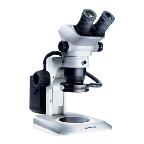
Evident SZX-AR1 User manual

Instructions
Note
This instruction manual is for the Evident SZX-AR1 System.
To ensure safety, achieve optimum performance, and familiarize yourself fully with
the use of this product, we recommend that you study this manual thoroughly
before operating it and ensure it is available for reference during operations.
For details about the products included in the configuration of this system, see
pages 16.
SZX-AR1 System
Optical Microscope and Accessory

This product is applied with the requirements of standard IEC/EN61326-1 concerning
electromagnetic compatibility.
- Emission Class A, applied to industrial environment requirements.
- Immunity Applied to industrial environment requirements.
Some interference may occur if this product is used in domestic location.
NOTE: This product has been tested and found to comply with the limits for a Class A digital
device, pursuant to Part 15 of the FCC Rules. These limits are designed to provide reason-
able protection against harmful interference when the product is operated in a commercial
environment. This product generates, uses, and can radiate radio frequency energy and, if
not installed and used in accordance with the instruction manual, may cause harmful inter-
ference to radio communications. Operation of this product in a residential area is likely to
cause harmful interference in which case the user will be required to correct the interfer-
ence at his own expense.
FCC WARNING: Changes or modifications not expressly approved by the party responsible for
compliance could void the user’s authority to operate the product.
FCC Supplier's Declaration of Conformity
Hereby declares that the product
Product name: Optical Microscope and Accessory
Model Number: SZX2-ARTTR
Conforms to the following specifications:
FCC Part 15, Subpart B, Section 15.107 and Section 15.109
Supplementary Information:
This device complies with part 15 of the FCC Rules. Operation is subject to
the following two conditions: (1) This device may not cause harmful interfer-
ence, and (2) this device must accept any interference received, including
interference that may cause undesired operation.
Responsible Party Name: Olympus Scientific Solutions Americas Corp.
Address: 48 Woerd Ave Waltham, MA 02453, U.S.A.
Phone Number: 781-419-3900
In accordance with European Directive on Waste Electrical and Electronic Equipment,
this symbol indicates that the product must not be disposed of as unsorted munici-
pal waste, but should be collected separately. Refer to your local our distributor in EU
for return and/or collection systems available in your country..
For Korea only

iii
SZX-AR1 System
Concept of this instruction manual ....................................................1
Product Concept ...................................................................................3
Safety precautions ................................................................................4
Handling precautions...........................................................................6
System requirements for the PC.......................................................10
1. Setup workflow ...............................................................................11
2. Unpacking and packing procedures ............................................12
1Unpacking procedure............................................................................................ 12
2Packing procedure................................................................................................. 13
3 Maintenance and Storage ..............................................................15
4 System diagram ...............................................................................16
1Diagram of the system with the SZX-ZB7 zoom microscope
body connected...................................................................................................... 16
2Diagram of the system with the SZX2-ZB10 zoom microscope
body connected...................................................................................................... 17
3Diagram of the system with the SZX2-ZB16 zoom microscope
body connected...................................................................................................... 18
5 Nomenclature of main operation parts........................................19
6 Observation procedure...................................................................20
7 Operation procedure of each unit.................................................21
7-1 Mounting Components......................................................................... 21
1Using the stage plate ............................................................................................ 21
2Placing the sample................................................................................................. 21
7-2 Main Body and Focus Unit.................................................................... 21
1Adjusting the tension of the coarse focusing knob and the
focusing knob......................................................................................................... 21
Contents

iv
7-3 Lens Barrel.............................................................................................. 22
1Interpupillary distance adjustment ..................................................................... 22
2Diopter adjustment (zoom parfocal adjustment) .............................................. 22
3Using the eye shades............................................................................................. 22
4Tilting adjustment.................................................................................................. 22
7-4 Observation and Camera Imaging...................................................... 23
7-5 Setting up the Software ........................................................................ 24
1Starting the system................................................................................................ 24
2Setting up Windows............................................................................................... 24
3Setting up the software......................................................................................... 25
4Configuring the microscope system.................................................................... 25
5Performing parfocal adjustment of the camera ................................................ 26
6Adjusting the AR image view................................................................................ 26
7Setting up the zoom magnification sensor ........................................................ 28
7-6 AR Trinocular Tube Operations............................................................ 29
7-7 How to Use the Zoom Magnification Sensor ..................................... 29
1Showing or hiding the AR image ......................................................................... 29
2Adjusting the brightness of the displayed AR image ........................................ 29
7-8 Barcode Reader Connection ................................................................ 30
7-9 External Switch Connection.................................................................. 31
8 Troubleshooting...............................................................................32
9 Specifications ...................................................................................34
10 Assembly procedures....................................................................36
10-1 Assembly Diagram .............................................................................. 36
10-2 Detailed Assembly Procedure............................................................ 37
1Attaching the zoom magnification sensor.......................................................... 37
2Attaching the AR tilting trinocular tube .............................................................. 38
3Attaching the eyepieces........................................................................................ 39
4Attaching the camera and camera adapter........................................................ 39

v
SZX-AR1 System
10-3 System Connections............................................................................ 40
1Connecting the power supply .............................................................................. 41
2Routing the cables ................................................................................................. 42
3Connecting to the power outlet........................................................................... 43
11 List of observation magnifications and observation
ranges .............................................................................................44
12 Software..........................................................................................45
12-1 Installation ........................................................................................... 45
1Install the software................................................................................................ 45
2Installing the device drivers for
DP23/DP28 ...........................................................46
3DP27 device driver installation............................................................................. 47
12-2 Uninstalling Software.......................................................................... 48
1Uninstalling
the software ......................................................................................... 48
2
Uninstalling the device driver for the AR trinocular tube device driver.......... 49
3Uninstalling the device driver for the camera.................................. 50
12-3 Updating the Software........................................................................ 51
12-4 Using the Primary Monitor Change Tool to Set Up
a Display .............................................................................................. 53
12-5 Collecting Log Files.............................................................................. 54
13 Setup Checklist...............................................................................56

1
Target group
This instruction manual describes the contents related to the whole SZX-AR1 system.
This instruction manual is intended for users operating the product according to "Intended uses" on page
3, as well as for EVIDENT distributors.
Read the instruction manual for the units you have purchased.
The following instruction manuals are prepared for the units used with this product. In addition to those
listed below, there are also instruction manuals for the units indicated by an ** mark in
"4 System diagram" on page 16.
Manual names Main contents
SZX-AR1 system (this manual) Explains how to operate the AR tilting trinocular tube SZX2-ART-
TR
DP23/DP28 Explains how to connect the DP23/DP28 digital camera
DP27 Explains how to connect the digital camera DP27
SZX16 Explains how to operate the stereo microscope system SZX16
SZX10 Explains how to operate the stereo microscope system SZX10
SZX7 Explains how to operate the stereo microscope system SZX7
U-TV0.63XC Explains how to connect the C-mount 0.63X camera adapter
U-TV0.5XC-3 Explains how to connect the C-mount 0.5X camera adapter
U-TV0.35XC-2 Explains how to connect the C-mount 0.35X camera adapter
In addition to the above, Online Help is provided on the software.
Structure of instruction manuals
Concept of this instruction manual

2
SZX-AR1 System
i
GX53
1
1
2
を登りながら
6
6-1 OOOOOOOOOO
OOOOOOOO
OOOOOOOOOO
OOOOOOOOOOOOOOOOOOOOOOOOOOOOO
OOOOOOOOOOOOOOOOOOOOOOOOOOOOO
OOOOOOOOOOOOOOOOOOOOO
OOOOOOOOOOOOOOOOOOOOO
OOOOOOOOOOOOOOOOOOOOO
This instruction manual is structured as follows.
How to read this instruction manual
Second level title
Third level title
The following symbols are used in this instruction manual.
DANGER : Indicates an imminently hazardous situation which, if not avoided, will
result in death or serious injury.
WARNING : Indicates a potentially hazardous situation which, if not avoided, could
result in death or serious injury.
CAUTION : Indicates a potentially hazardous situation which, if not avoided, may
result in minor or moderate injury. It may also be used to alert against
unsafe practices or potential material damage.
NOTE
: Indicates a potential situation which, if not avoided, may result in failure
of this instrument.
TIP
: Indicates useful knowledge or information for use.
First level title
2
1
Cautions and references
Operating procedure
Loosen the clamping screw
A
with a screwdriver.
Remove the unit
B
.
TIP
NOTE
CAUTION
1
,
2
...indicates the opera-
tion procedure, and A,B
...indicates the component
for the operation.
B
A

3
Product outline
Microsoft, Excel, and Windows are either registered trademarks or trademarks of Microsoft Corporation in
the United States and/or other countries.
Intel and Intel Core are trademarks of Intel Corporation or its subsidiaries in the United States and/or other
countries.
QR code is a registered trademark of DENSO WAVE Incorporated.
Other company names or product names described in this manual are either registered trademarks or
trademarks of their respective companies.
HDMI, High-Definition Multimedia Interface, and the HDMI logo are trademarks or registered trademarks of
HDMI Licensing Administrator, Inc. in the United States and other countries.
The terms HDMI and HDMI High-Definition Multimedia Interface, and the HDMI Logo are trademarks or
registered trademarks of HDMI Licensing Administrator, Inc. in the United States and other countries.
THIS PRODUCT IS LICENSED UNDER THE AVC PATENT PORTFOLIO LICENSE FOR THE PERSONAL AND
NONCOMMERCIAL USE OF A CONSUMER TO (i) ENCODE VIDEO IN COMPLIANCE WITH THE AVC STANDARD
("AVC VIDEO") AND/OR (ii) DECODE AVC VIDEO THAT
WAS ENCODED BY A CONSUMER ENGAGED IN A PERSONAL AND NONCOMMERCIAL ACTIVITY AND/OR WAS
OBTAINED FROM A VIDEO PROVIDER LICENSED TO PROVIDE AVC VIDEO. NO LICENSE IS GRANTED OR SHALL
BE IMPLIED FOR ANY OTHER USE. ADDITIONAL INFORMATION MAY BE OBTAINED FROM MPEG LA, L.L.C. SEE
HTTP://WWW.MPEGLA.COM
The SZX-AR1 system can superimpose the digital contents as Augmented Reality on the image observed
through the eyepieces of the stereo microscope.
Trademarks and licenses
Product Concept
Precautions and points for confirmation before use
When you unpack the package, check all the included items referring to the list of accessories. If any
components are missing or damaged, contact an Evident distributor.
A list of the enclosed components can be downloaded from the same website as this instruction manual.
Use cases for this product
·Assembly and inspection work in manufacturing processes
·Creation of assembly and inspection manuals
·Training related to basic skills and assembly/inspection skills
Suitable samples include semiconductors, electronic components, molded products, and mechanical parts.
Industrial applications include observation, inspection, and measurement.
Do not use this product for any purpose other than the intended use.
Intended uses

4
SZX-AR1 System
Safety precautions
If this product is used for any purpose other than those described in this instruction manual, this could
cause safety issues or product failure. Always use the product according to this instruction manual.
Prevention of electric shock
• Never disassemble any part of this product.
It could cause electric shock or product failure.
• Do not touch the product with wet hands.
In particular, if you touch the main switch of the power unit or the power cord with wet hands, this
could cause electric shock, fire, or product failure.
• Do not bend, pull, or tie up the power cord or cables.
Otherwise they could be damaged, causing a fire or an electric shock.
WARNING
• Always use the power cord specified by us.
If the proper AC adapter and the power cord are not used, the electric safety and the EMC
(Electromagnetic Compatibility) performance of the product intended by us cannot be assured. If
no power cord is provided, please select the proper power cord by referring to the section "Proper
selection of the power cord" at the end of this instruction manual.
• Always connect the ground terminal.
Connect the ground terminal of the power cord to the ground terminal connection of your
electrical socket.
If the product is not grounded, the intended electric safety and EMC performance of the product
cannot be assured.
• Do not use the product in close proximity to sources of strong electromagnetic radiation.
Proper operation may be interfered. The electromagnetic environment should be evaluated prior
to operation of the product.
• Disconnect the power cord in case of emergency.
In case of emergency, disconnect the power cord from the power cord connector on the product
or from the power outlet.
Install the product at the location where you can reach the power cord connector or the power
outlet at hand to disconnect the power cord quickly.
• Do not connect or disconnect the power cord, cables, or units while the power is ON.
CAUTION
Electric safety

5
The following symbols are placed on this product.
Study the meaning of the symbols and always use the product in the safest possible manner.
Symbol Meaning
Indicates a non-specific general hazard. Follow the cautions given after this
symbol or in the instruction manual.
Indicates that the seesaw type main switch is ON.
(Seesaw switches are a type of switch that selects ON or OFF by pressing it to
the ON or OFF side.)
Indicates that the seesaw type main switch is OFF.
Label position and instructions
Components which require particular care for usage and operations are marked with a caution indication.
Always follow these instructions.
Label position Label Instructions in instruction
manual Page
Back side of AR tilting trinocular tube
Safety precautions - Electric
safety Page 4
Safety precautions -
Prevention of electric shock
If caution labels get dirty or peel off, contact an Evident distributor for assistance.
Safety symbols

6
SZX-AR1 System
Handling precautions
Restrictions
·When linking units of the SZX7 system, SZX10 system, or SZX16 system with this system, never use this
system as a medical instrument, for diagnostics, or for similar purposes.
·Each focusing unit has a limit in load capacity. "Load capacity of focusing unit" on page 8 See "Load
capacity of focusing unit" on page 7, and do not use a combination that exceeds the load capacity.
·This system displays dimensions and magnifications but their accuracy is not guaranteed. Therefore,
these values should be used for reference only.
·This system is not dustproof or mold-proof.
·This system does not support ESD.
·If you move your line of sight while looking into the AR tilting trinocular tube, the AR image may shake.
·If the sample is not in focus, the AR image may appear doubled.
·If you change the zoom magnification, the depth perception of the AR image may change.
·If the focus adjustment knob is not in the click position, the AR image is not displayed.
·When acquiring images with the camera, the light (room light, etc.) through the eyepieces may appear
on the image. In this case, put on the eyepiece cover provided with the AR tilting trinocular tube before
conducting imaging.
·If you increase the exposure time of the camera when the observed image is dark and also the AR image
brightness is set to maximum, flares or ghosts may appear on the acquired image.
·When observing highly reflective samples, flares or ghosts may appear on the image.
·For the observable ranges on sample surfaces through the eyepieces and the camera when using the
objective lens at 1x magnification, see "7-4 Observation and Camera Imaging" on page 23.
·If you observe the image with the camera exceeding the observable range through the eyepieces, the
peripheral light may be insufficient if the zoom magnification is set to the minimum.
·During observation, some areas around the field of view may appear darker than the center of the field
of view.
·If the diopter of the eyepiece is not adjusted correctly, the camera image may not be focused even
though the sample is in focus. If the camera image is still blurry even after adjusting the diopter, adjust
focus and carry out imaging while checking the camera image on the monitor.
·Before adjusting the tension of the focusing unit, lower the focusing unit to the lowest position.
General precautions
• This product is a precision instrument. Treat this product with care and avoid subjecting it
to impacts.
• Disassembling the product could cause unexpected accidents or failure. Neverdisassemble
the product.
• Do not use the product in areas where it may be subjected to direct sunlight, high humidity,
dust, vibrations or out of operating temperature range (10°C to 35°C). Otherwise the
product may be damaged.
(For operating environment conditions, see "9 Specifications" on page 34.)
• For units which can be attached to this product, see pages 16, 17, and 18.
The use of this product in combination with other units not only creates the risk of abnormal
operation, but may also damage the product.
• Before disposing of this product, be sure to follow the regulations and rules of your local
government.
NOTE

7
·When the zoom magnification sensor is attached, minor scratches may be made on the focus adjustment
knob.
·The magnification indicated on the focus adjustment knob may differ from the total magnification shown
in the software in the following cases. To avoid this confusion, remove the magnification indication
sticker or the magnification ring attached to the focus adjustment knob before use.
(a) When the magnification ring provided with the objectives (DFPL0.75X-4, DFPLAPO1.25X,
SZX-ACH1.25X-2, DFPL1.5X-4, or DFPL2X-4) is attached.
(b) When the magnification indication sticker provided with the ergonomic trinocular tube SZX2-LTTR is
attached.
·Attach the extendable eyepoint adjuster, AS unit (SZX-XB7 only) and coaxial reflected light illumination
unit between the AR tilting trinocular tube and the zoom microscope body in this order from top.
·With the SDFPLAPO1.6XPF or SDFPLAPO2XPFC objective, vignetting may occur when the zoom is set at
low magnification.
·If you use the extendable eyepoint adjuster function to set the eyepoint height at 150 mm, set the zoom
magnification to the minimum, and set the AS to a value other than maximum, vignetting occurs in the
area around the field of view.
·Ghosting may appear on the edges of images captured with the camera if the extendable eyepoint
adjuster function is being used at a height of 50 mm or more.
·This system does not support the location change of the PC. Therefore, use the OS keeping the language
setting made at setup, i.e. Japanese or English. (The change of time zone is supported.)
·When connecting the camera via USB, connect directly to the device without a USB hub or other
intermediary device.
·The AR tilting trinocular tube cannot be used if it is connected to SZX2-ARTTR via a VGA analog signal
converter.
·The camera function cannot be used on the software without connecting the AR tilting trinocular tube.
Confirm that the connection of the AR tilting trinocular tube and the camera is recognized.
·Tilting the zoom microscope body after mounting the zoom magnification sensor to it may cause the
sensor to display incorrect values. To use it tilted, set up the zoom magnification sensor again.
·If the temperature increases or decreases by 25°C or more or the humidity increases or decreases by 30%
or more after the product is set up, the zoom magnification sensor value may not be obtained correctly.
Adjust the zoom magnification sensor again if necessary.
·On the AR image on the eyepiece side, the graphics and text that can be displayed on the AR image and
the black areas of the image are displayed transparent when they are displayed on the software.
·When using the SZX-ZB7 zoom microscope body in combination with the AS unit, or when using the
SZX2-ZB10 zoom microscope body or the SZX2-ZB16 zoom microscope body, if the aperture diaphragm is
stopped down, vignetting may occur.
·Do not use a microscope instrument that is not registered in the software. The incorrect dimension
information may be displayed.

8
SZX-AR1 System
Weight of each unit
Category Product name Weight
[kg]
AR tilting
trinocular tube
AR tilting trinocular
tube 3.7
Zoom magnification
sensor 0.4
Eyepiece
WHSZ10X-H (2units) 0.22
WHN10X-H (2units) 0.27
Camera
DP23-CU/DP28-CU 0.38
DP27-CU 0.16
Camera adapter
U-TV0.35XC-2 0.14
U-TV0.5XC-3 0.27
U-TV0.63XC 0.43
Extendable
eyepoint adjuster SZX2-EEPA 2.1
AS unit SZX-AS 0.3
Coaxial reflected
light illumination
unit
SZX2-ILLC10 0.84
Zoom microscope
body
SZX-ZB7 0.96
SZX2-ZB10 1.3
SZX2-ZB16 1.3
Load capacity of focusing unit
Product name Load capacity [kg]
Focusing unit SZX2-FO 10
Coarse and fine dynamic focusing unit SZX2-FOF 15
Standard stand SZ2-ST 7
Load capacity of focusing unit
Weight of each unit
Category Product name Weight
[kg]
Focusing adapter SZX-STF 0.5
Objective
DFPL0.5X
+SZ2-ET 0.536
DFPL0.75X 0.356
DFPLAPO1X-4 0.418
SZX-ACH1X 0.18
DFPLAPO1.25X 0.54
SZX-ACH1.25X 0.26
DFPL1.5X 0.466
DFPL2X 0.615
Ring light guide
adapter SZX-LGR66 0.097
4-part LED ring
illumination unit SZX2-ILR66 0.47
6-point ring light
guide SZ2-CLGR 0.29
Ring light guide LG-R66 0.45
LED illumination
unit SZ-LW61 0.12

9
Precautions for the PC
·The PC data may be lost (corrupted) unexpectedly. Be sure to back up the data frequently.
·We are not liable for any damage (including compensation for the corrupted PC data) caused by the use
or the inability to use the product.
• When themes other than standards are set on the Windows®desktop, the software window
may not be displayed or printed properly.
• If you use the PC that does not meet the system requirements and operating environments,
the correct operation of the product cannot be assured. Contact our distributors for the PC
models where operations have been confirmed by us.
• If this product is used in connection with a network, the product may not work properly due
to the following causes.
• Virus infection through the network
• Malfunction caused by applying OS service pack, security patch, or updating third party
software including runtime libraries
• If this product is used in connection with a network, the use of security software is
recommended.
• If the unexpected behavior occurs, disconnect the product from the network, restore to the
factory defaults and check whether the product operates properly.
• The following tasks should be done by customers even if the PC was kitted by us. We are not
responsible for any incidents that occur caused by your failure to perform these tasks.
• Change the password
• Install security software
• Comply with the security policy of the facilities where this system is used
• The default settings of DP2-PC-M are as follows:
• Automatic login: Enabled
• Account: olympus
• Password: olympus
• Olympus account authority: Administrator
If the instruction manual provided with DP2-PC-M lists an account and password, use these.
• The operation of this system cannot be guaranteed if the PC environment is changed as
follows.
• Change in settings caused by applying OS service pack, security patch, or updating third party
software including runtime libraries
• Change in settings caused by installation of software other than SZX-AR1-APP or version
upgrades
• If a problem occurs in the system due to a change in the PC environment or inappropriate
actions by a third party, we are not responsible for a full recovery to the environment
before the event occurred.
• Please be aware that we are not responsible for indemnity or compensation for any loss of
profit which may occur due to inappropriate actions (server attacks, virus infections, server
damage, or hacking) by third parties via networks and that we make no guarantee that
there will be no other risks related to other security infiltration.
• We are not responsible for the following phenomena in the event of a system overload
occurring due to the use of anti-virus software, etc.
• Loss of data (loss of audio or images) or flickering images while recording video
• Reduced processing speed of the this system
• Flickering of observed live image or reduced EPS
• Deteriorated operability, loss of acquired images, delay or stop of operations
• Please be aware that we are not responsible for indemnity or compensation for loss
of profit due to the occurrence of incidents such as the falsification or destruction of
confidential information due to lost information in a PC or external memory device
(HDD, SSD, etc.) or threats such as unauthorized direct or physical interference with the
instrument by a third party.
• If this product is connected to the PC via a network, the use of security software is
recommended.
NOTE

10
SZX-AR1 System
·The PC used with this system should be conformed to IEC/EN60950-1 or IEC/EN62368-1.
·The system requirements for the PC used with this system are listed below. Even if the system
requirements below are met, we do not guarantee the operation of the systems in combination with all
commercially-available PCs.
Item Specifications
OS
Windows 10 Pro (64bit), Windows 10 pro for Workstation (64bit)
Windows 10 version: 2004, 21H1
Windows 10 IoT Enterprise LTSC 2019 (only when combined with DP23/DP28)
OS language Japanese, English
Processor 10th generation Intel®Core™ i5 equivalent or better
(Recommended core: 4 or more, clock frequency: 3.2 GHz)
Memory 8 GB or more
Storage capacity required
to install software
1 GB or more free space
Graphic controller Intel UHD Graphics 630 or more
Monitor resolution 1366 x 768 or more
USB interface • USB2.0 Type-A x 1 (for connection with AR tilting trinocular tube)
• USB2.0 Type-A x 1 (for zoom magnification sensor)
• USB3.1 Type-A x 1 (for use with DP23/DP28) / USB3.0 Type-A x 1 (foruse with
DP27)
Monitor interface • HDMI x 1 (for connection with AR tilting trinocular tube)
• HDMI 1.4 or more
• HDMI connector: Type-A
System requirements for the PC

11
"12-1 Installation"
1Install the software* ……………………………………… (page 45)
"12-1 Installation"
2DP23/DP28 device driver installation*
………………………………………………………………………… (page 46)
3DP27 device driver installation*
………………………………………………………………………… (page 46)
Unpack the units. "2. Unpacking and packing procedures"
1Unpacking procedure …………………………………… (page 12)
Section name (Page)
"10-1 Assembly Diagram" …………………………………… (page 36)
"10-2 Detailed Assembly Procedure" …………………… (page 37)
Assemble the instrument.
Camera device driver installation
Connect the cables.
Setup the system.
Start
Finish
Check the setup
"10-3 System Connections" ………………………………… (page 40)
1Connecting the power supply ………………………… (page 41)
2Routing the cables ………………………………………… (page 42)
3Connecting to the power outlet ……………………… (page 43)
"6 Observation procedure" …………………………………… (page 20)
"7-1 Mounting Components" ……………………………… (page 21)
"7-2 Main Body and Focus Unit"* ………………………… (page 21)
"7-3 Lens Barrel"*………………………………………………… (page 22)
"7-5 Setting up the Software"*……………………………… (page 24)
"7-8 Barcode Reader Connection"* ……………………… (page 30)
"7-9 External Switch Connection" ………………………… (page 31)
"13 Setup Checklist"* …………………………………………… (page 56)
This section lists the order of preparations and setup tasks to perform to get your SZX-AR1 system ready to
use.
This section also describes the usage and adjustments related to the assembly procedure.
Be sure to operate the procedure in the order from the top.
When removing units, use the reverse order. (The procedures marked with an asterisk (*) are not necessary
for removal.)
11. Setup workflow
Install the software.

12
SZX-AR1 System
Take off the top lid to open the packing box and remove the
internal pad cover while paying attention not to damage the
product.
The cables are packed as shown in the picture on the left. Re-
move them and pull out the top pad Afrom the packing box.
1
2
Insert your fingers into the concave part for taking out the AR
trinocular tube Con the bottom pad B, and scoop up the
AR tilting trinocular tube Dto remove it.
• When removing the AR tilting trinocular tube, be
careful not to make the wiring clamp Ecaught by
the pad or apply the impact on it.
• Do not hold the eyepiece mount Hwhen taking out
or carrying the AR tilting trinocular tube. Unexpected
accidents or failure may be caused.
• The center of gravity of the AR tilting trinocular tube
is on the eyepiece mount side. When taking out the
AR tilting trinocular tube, be careful not to lose the
balance.
Remove the clamp Fof the zoom magnification sensor and
the zoom magnification sensor Gfrom the bottom pad B.
If you need to pack this product, such as to ship to
the distant location, you must use the packing box,
pads and plastic bags. In this case, always contact
an Evident distributor for assistance.
3
NOTE
4
NOTE
1Unpacking procedure
A
C
F
G
Insert fingers into the concave part to
remove the AR tilting trinocular tube Bon
the bottom pad C.
D
E
When unpacking, the product and component units will
be packed in plastic bags. In this section, to make the
explanation and illustration easy to understand, the
photos showing the status where these items are taken
out from the plastic bags are used.
TIP
B
C
H
E
22. Unpacking and packing procedures
2
3 4
B
3

13
2Packing procedure
F
Before performing procedures in this section, attach the
eyepiece caps and the cap of the straight tube to mount the
camera adapter.
Before packing the AR tilting trinocular tube, minimize the
interpupillary distance of the eyepiece mount Aand set the
tilting angle to the lowest point.
To lower the tilting angle, hold the eyepiece mount A
with one hand while holding the top surface of the ob-
servation tube with the other hand, and set the tilting
angle to the lowest point.
Insert the zoom magnification sensor clamp Cinto the zoom
magnification sensor Band tighten the two mounting screws
Ewith the mark Don the clamp in position.
Put the product and the units back into the plastic bags you
retained after unpacking them.
When packing the product and the units, pack them
kept in the plastic bags. In this section, to make the
explanation and illustration easy to understand, the
photos showing the status where these items are taken
out from the plastic bags are used.
Insert the bottom pad Finto the bottom of the packing box.
Put your finger on the bottom surface of the AR tilting trinocular
tube and insert your hand into the concave part for taking out
the AR tilting trinocular tube Gon the bottom pad. Then, put
the AR tilting trinocular tube into the pad.
When removing the AR tilting trinocular tube, be
careful not to get the wiring clamp Hcaught on
the pad or subject it to impact.
1
2
TIP
3
4
TIP
5
NOTE
HG
Insert fingers into the concave part to
take out the AR tilting trinocular tube F
on the bottom pad H.
2
3
A
5
E
D
B
C

14
SZX-AR1 System
I
K
K
J
J
7
8
C
B
F
6Insert the clamp Cof the zoom magnification sensor and the
zoom magnification sensor Binto their respective positions.
At this time, insert the zoom magnification sensor Binto the
bottom pad Fwith the larger diameter side facing down.
Place the top pad Fon the bottom pad I.
At this time, place the top pad Jso that the convex parts K
(6 positions) of the bottom pad and the convex parts I(6
positions) of the top pad are aligned.
Put the AC adapter in the left hand space, and put the cables,
eyepiece cover, instruction manual, and DVD (photos of the
instruction manual and the DVD are omitted to simplify the
explanation) in the right hand space of the top pad I.
Attach the internal pad cover and close the lid of the packing
box.
• Make sure that the internal pad cover is attached
in the correct direction. If not, the top lid does not
close. With the protrusion on the internal pad cover
facing down, attach the internal pad cover so that
the protrusion is housed in the right-side space of
the top pad I.
• Close the packing box and seal it securely so that it
does not open during transportation.
6
7
8
9
NOTE
F

15
Lifetime
The lifetime of this system is approximately 5 years after purchase if the product is used properly according
to this instruction manual.
When using SZX2-ARTTR with the unit you are using, follow the lifetime of the unit you are using.
To clarify any of these points, contact the retailer where you purchased the system.
Cleaning of each unit
Lenses and filters
Be careful to avoid stains, fingerprints, and other impurities on the lenses and filters. If they get dirty, blow
away dust with a commercially available blower and gently wipe the lenses or filters with a piece of cleaning
paper (or washed clean gauze). Only when cleaning fingerprints and oil stains, slightly moisten a piece of
cleaning paper with commercially available absolute alcohol and wipe them off with it.
Since absolute alcohol is highly flammable, it must be handled carefully. Be sure to keep it
away from open flames or potential sources of electrical sparks.
For example, the electrical equipment that is switched ON and OFF may cause the ignition of a
fire. Also, always use absolute alcohol only in a well-ventilated room.
Parts other than lenses
Wipe the parts other than lenses with a dry soft cloth. If dirt/dust cannot be removed by dry-wiping, moist-
en a soft cloth with diluted neutral detergent and wipe off dirt/dust with it.
Do not use organic solvents because they may deteriorate the coated surface or plastic
parts.
WARNING
NOTE
Daily inspection of the zoom magnification sensor
Click [Setup] on the Home screen.
1
33Maintenance and Storage
2
3
Rotate the focus adjustment knob and check whether the
correct magnification is displayed.
If the correct magnification is not displayed, click the [Adjust]
button to adjust the magnification. See page "Setting up the
zoom magnification sensor" on page 28 for the adjustment
method.
2
3
1
Other manuals for SZX-AR1
1
Table of contents
Other Evident Microscope manuals
