ASSEMBLY & INSTALLATION INSTRUCTIONS
Trim Kit for Evo Affinity 30G
10
Evo America, LLC 20360 SW Avery Ct., Tualatin, OR 97062 USA
TRIM KIT ASSEMBLY & INSTALLATION
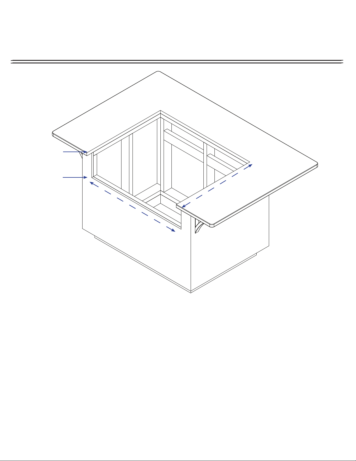
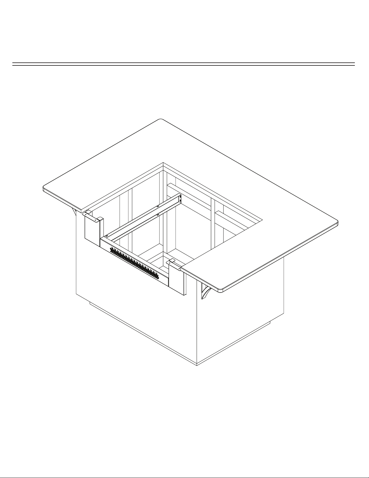
STEP 4: With 3/8” wrench, loosen and turn the eleven (11) installed Universal Mounting
Brackets on Top Pan to a vertical position. Loosely attach rear of Trim Kit Top to cabinet with
two (2) Universal Mounting Brackets and two (2) screws (not included) to hold up and check
for fit.
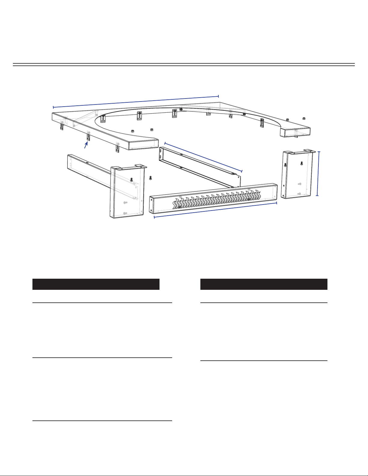
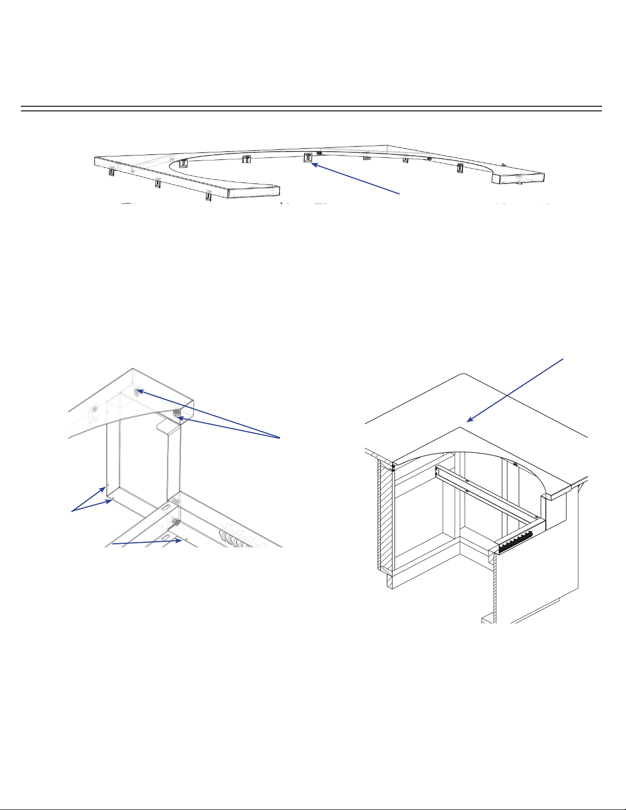
Fasten Top Pan to End Cap
using 1/4” - 20 x 1/2” SS
Phillips Head Screw with Nyloc
Nut.
Turn all eleven (11) Universal Mounting
Brackets to vertical position.
STEP 5: Fasten Top Pan to End Cap using four (4) 1/4”- 20 x 1/2” SS Phillips Head
Screw and Nyloc Nuts as shown. Next shim, level and readjust until Top Pan is flush with
countertop. Secure Top Pan with the remaining nine (9) Universal Mounting Brackets and
nine (9) additional suitable construction screws (not included). It may be necessary to adjust
the location of the Universal Mounting Bracket with a 3/8” open end wrench to align with
cabinet frame. For more stability, secure Trim Kit with up to eleven (11) more screws (not
included) in provided holes as shown.
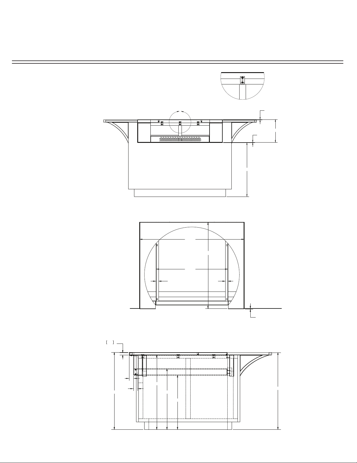
It is recommended the Trim Kit Top
Pan be level and flush to the adjoining
countertop surface.
For more stability add up to
eleven (11) screws in provided
holes.