Evolution FORESTER Series User manual

EVOLUTION ELECTRIC VEHICLES INC
California Headquarters:2620 Palisades Drive, Corona CA 92882
Florida Operations: 7600 Narcoossee Rd, Orlando, FL 32822
Email: info@evolutionelectricvehicle.com
Website: http://www.evolutionelectricvehicle.com
Copyrighted Material
EVOLUTION ELECTRIC VEHICLES INC reserves
the right to change or improve the manual
according to products and company policy alterations
at any time without notice.
EVOLUTION
OWNER’S MANUAL
Copyright CEVOLUTION ELECTRIC VEHICLES INC
VERSION: 202105
FORESTER SERIES

OWNER MANUA L PAG E A
EVOLUTION
TABLE OF CONTENTS
Read carefully all the safety statements before attempting any procedure.
EVOLUTION
PAG E B OWNER MANUA L
Read carefully all the safety statements before attempting any procedure.
TABLE OF CONTENTS
SAFETY INFORMATION.........................................................................1
Safety Signal Words.............................................................................1
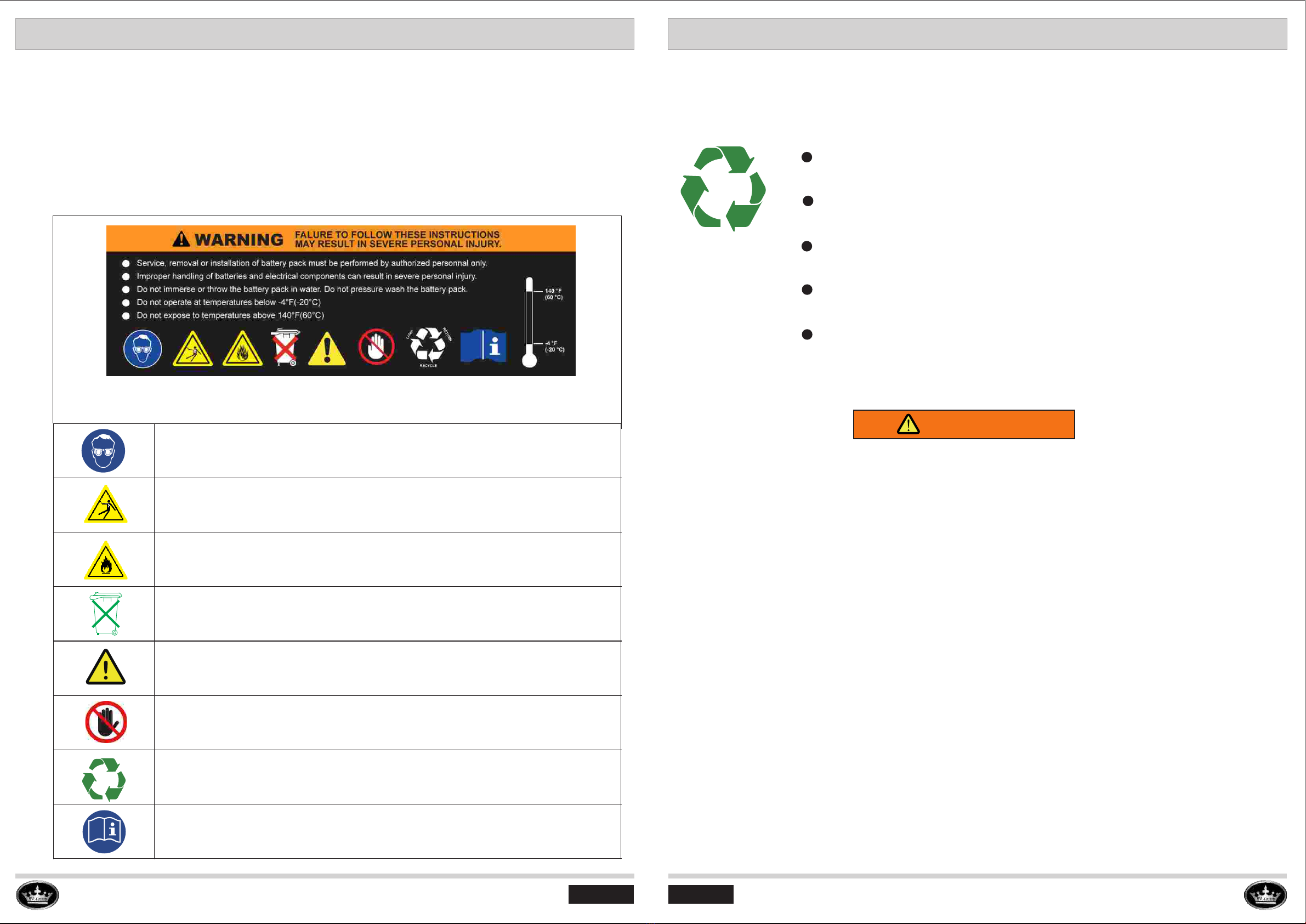
Vehicle Safety Labels...........................................................................2
Battery Safety Information....................................................................3
Lithium-Ion Battery Recycling...............................................................4
Vehicle Safety Labels Location..............................................................5
VEHICLE SERIAL NUMBER LOCATION..................................................7
Vehicle Serial Number..........................................................................7
Vehicle Vin Number..............................................................................8
VEHICLE FEATURES.............................................................................9
Vehicle Overview.................................................................................9
Front View.......................................................................................9
Rear View........................................................................................9
Rear Seat And Golf Bag Attachment Kit Overview..................................10
Dash Board Overview................................................。.......................11
OPERATION AND CONTROLS..............................................................11
Pre-Operation Safety And Performance Inspection...............................12
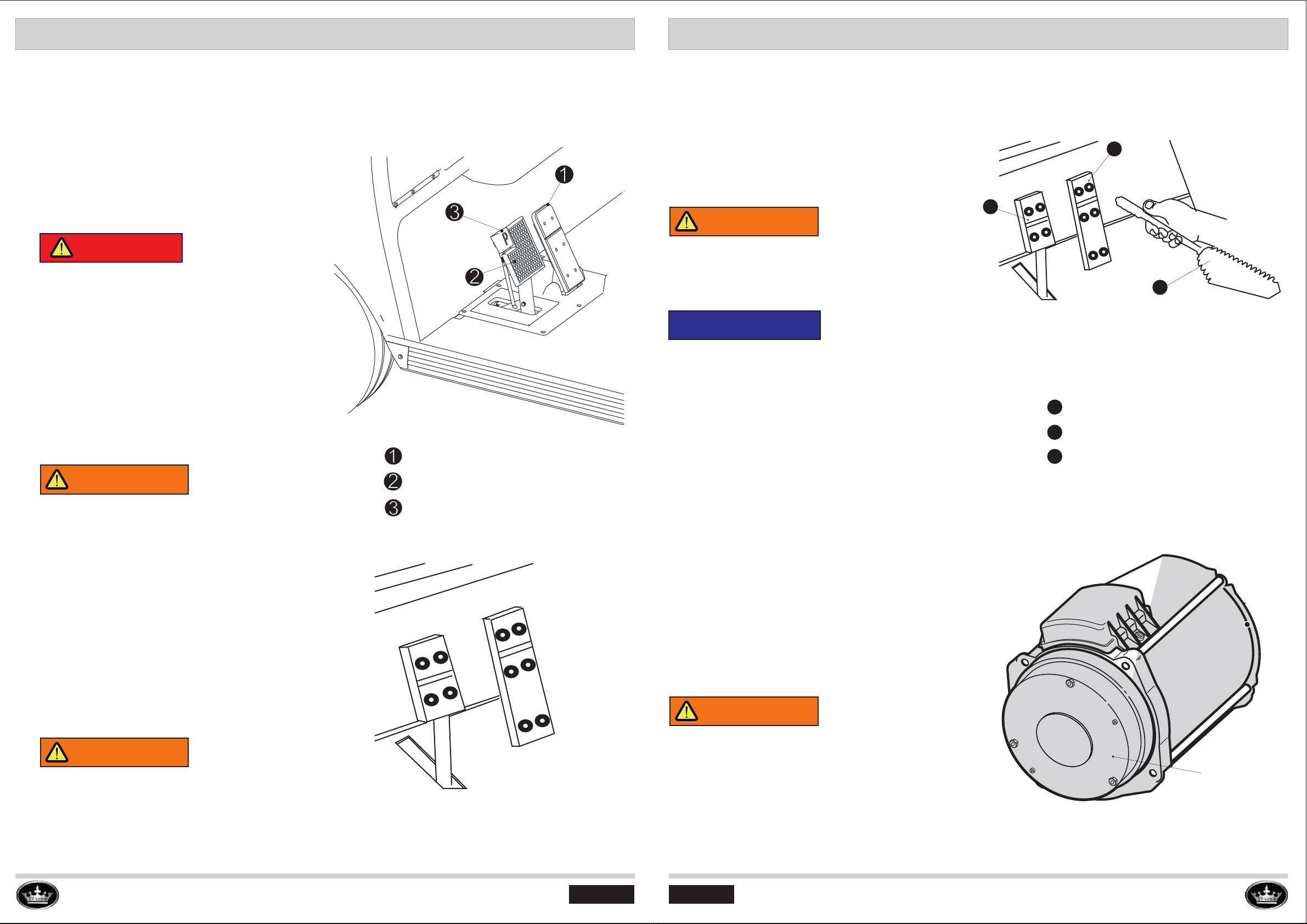
Accelerator Pedal Operation...............................................................15
Brake Pedal Operation.......................................................................15
Foot Parking Brake Pedal (Mechanical Brake).....................................15
Hand Parking Brake (Hydraulic Brake)................................................16
Motor Brake Operation (Optional).......................................................16
Key Switch Operation.........................................................................17
Forward/Neutral/Reverse Control (D/N/R Knob Switch)........................17
High/Low Speed Model Selecting Switch (Optional).............................18
Usb Drive Port & Use Charger Outlet..................................................18
Combination Switch Control...............................................................19
Front Headlight Control..................................................................19
Turning Signal Lights Control..........................................................19
Horn Control..................................................................................19
Motor Brake Release Switch (Electrical).............................................20
Motor Brake Release Screws (Mechanical).........................................20
Motor Brake Release Lever (Mechanical)............................................20
How To Operate A Golf Cart................................................................20
Rear Seat Kit Operation.......................................................................20
BATTERY.................................................................................................25
Lithium Battery Overview........................................................................25
Lead Acid Battery Overview....................................................................26
Battery Meter.........................................................................................27
Battery Maintenance .............................................................................27
BATTERY CHARGER...............................................................................31
Battery Charger Specification.................................................................31
Charger Led Display..............................................................................32
How To Use Charger..............................................................................33
Charger Maintenance............................................................................34
TOUCHSCREEN......................................................................................35
Touchscreen Overview And Introduction..................................................35
Touchscreen Operation..........................................................................36
SPEEDOMETER......................................................................................41
Speedometer Overview..........................................................................41
Speedometer Operation.........................................................................42
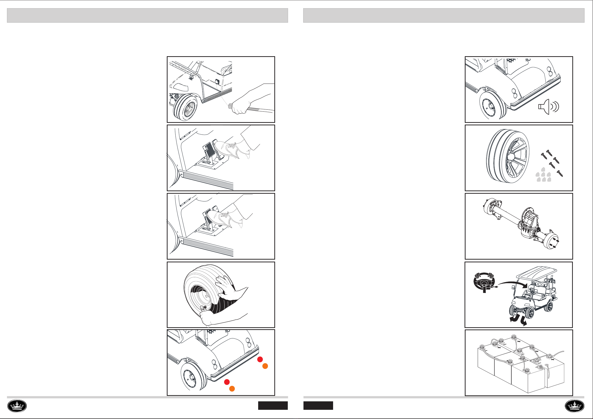
TIRE OPERATION....................................................................................43
LIFT AND LOWER THE VEHICLE..............................................................44
VEHICLE MAINTENANCE.........................................................................45
Vehicle Scheduled Maintenance Chart....................................................46
Chassis Maintenance............................................................................47
Electrical Components Maintenance.......................................................49
Vehicle Cleaning And Care.....................................................................51
Vehicle Storage.....................................................................................52
Vehicle Transportation And Towing..........................................................54
VEHICLE GENERAL SPECIFICATIONS.....................................................55
MAINTENANCE LOG................................................................................57

OWNER MANUA L PAG E 1
EVOLUTION
SAFETY INFORMAT ION
Read carefully all the safety statements before attempting any procedure.
EVOLUTION
PAG E 2 O WN ER MANUAL
Read carefully all the safety statements before attempting any procedure.
SAFETY INFORMAT ION
Replace missing, damaged, or unreadable safety decals immediately to prevent possible
property damage, personal injury, or death. Purchase replacement safety decals from your
dealer or distributor.
Know and understand all laws and regulations for vehicle operation in your area.
Speak with your dealer or distributor if you have questions about material contained in this
manual or the vehicle.
Signal words (DANGER, WARNING, CAUTION, and NOTICE) and safety messages are in
this manual and on safety decals. Read, understand, and obey all instructions, safety
precautions, and safety decals before vehicle operations. Safety messages are necessary
and must be obeyed.
DANGER
WARNING
CAUTION
NOTICE
Safety Signal Word Safety Signal Word
The safety alert symbol is used to alert you to possible
personal injury hazards. Obey all safety messages that
follow this symbol to prevent possible injury or death.
A DANGER identifies a hazardous situation which will
result in death or serious injury.
A WARNING identifies a hazardous situation which
could result in death or serious injury.
A CAUTION identifies a hazardous situation which could
result in minor or moderate injury.
A NOTICE identifies a hazardous situation which could
result in property damage.
VEHICLE SAFETY LABELS
Operation Instruction Decal
Dash Warning Decal
Windshield Warning Decal
Rear Seat Kit Warning Decal
Rear Seat Warning Decal
Battery Warning Decal
SAFETY SIGNAL WORDS

OWNER MANUA L PAG E 3
EVOLUTION
Read carefully all the safety statements before attempting any procedure.
EVOLUTION
PAG E 4 O WN ER MANUAL
Read carefully all the safety statements before attempting any procedure.
LITHIUM-ION BATTERY DISPOSAL
Battery Warning Decal
BATTERY SAFETY INFORMATION
SAFETY INFORMAT ION SAFETY INFORMAT ION
Explosion and fire hazard. The terminals of a li-ion battery are always live,
therefore do not place metallic items or tools on top of a li-ion battery. Avoid
short circuits.
Explosion and fire hazard. The terminals of a li-ion battery are always live,
therefore do not place metallic items or tools on top of a li-ion battery. Avoid
short circuits.
Batteries must not be mixed with domestic or industrial waste .
Do not touch any electrical components without any insulation
protection.
Batteries marked with the recycling symbol must be processed via a
recognized recycling agency.
Observe these instructions and keep them located near the battery for
future. Read, understand and comply with all warning and instructions.
While working on a li-ion battery wear protective eyeglasses and clothing
Do not open or dismantle the battery. Electrolyte is very corrosive.
If the battery casing is damaged do not touch the exposed electrolyte or
powder because it is corrosive.
Safety and warning labels are on the lithium battery for your protection. Read and comply with
the instructions on the labels carefully for avoiding the potential risks or injury. if any label
shown below is damaged or comes off or becomes illegible, contact your Evolution dealers for
a replacements, printed on the labels, or can be obtained from your dealer.
WARNING
Lithium -ion batteries are recyclable.
Lithium-ion batteries must be collected and recycled separately from
other waste.
Do not discard lithium-ion batteries as municipal waste.
Speak with your dealer or distributor on returning or recycling used or
damaged battery packs.
Contact local or state environmental department for disposal information.
Failure to operate the vehicles as instructed can cause collision, loss of control or roll
over, resulting in severe injury or death. Follow all safety warnings or labels in this owner
manual. All operator must read, understand and comply with these warnings and labels
before operating the vehicles. Follow the safety information and operating procedures
described.
• Operate your vehicle responsibly to prevent dangerous conditions for the operator, passengers
and other people in the area of operation
• Operate your vehicle responsibly and keep the vehicle in safe condition of operation
• The driver must keep both hands on the steering wheel and both feet on the floor or pedals.
• Inspect the vehicle before each use to make sure it is in safe operating condition. Perform the
daily inspection described in this manual.
• Always have the vehicle checked by an authorized dealer if it is involved in an accident.
• Remove the key when the vehicle is not in use to prevent accidental starting or unauthorized use.
• Drive the vehicle at appropriate speeds for the terrain and conditions. Be aware of environmental
conditions that change the terrain and your ability to control the vehicle.
• Do not drive on excessively steep hills. Evaluate the terrain before descending a hill. Drive slowly
and deliberately. Use the brake to limit speed and maintain control. Sudden braking or turning can
cause loss of vehicle control. Drive straight up or down the hill; do not drive across the hill.
• Operate only in approved areas. Follow all applicable safety rules for the area.

OWNER MANUA L PAG E 5
EVOLUTION
SAFETY INFORMAT ION
Read carefully all the safety statements before attempting any procedure.
EVOLUTION
PAG E 6 O WN ER MANUAL
Read carefully all the safety statements before attempting any procedure.
SAFETY INFORMAT ION
VEHICLE SAFETY LABELS LOCATION VEHICLE SAFETY LABELS LOCATION

OWNER MANUA L PAG E 7
EVOLUTION
Read carefully all the safety statements before attempting any procedure.
EVOLUTION
PAG E 8 O WN ER MANUAL
Read carefully all the safety statements before attempting any procedure.
VEHICLE VIN NUMBER (Only for LSV cart)
VEHICLE SERIAL NUMBER
VEHICLE SERIAL NUMBER LOCATION VEHICLE SERIAL NUMBER LOCATION
All have vehicle’s serial number on the left side of the chassis frame. The front four numbers
are the manufacturing year of the vehicle, the other five numbers are the vehicle’s serial
number given by Evolution Electric Vehicles. All the vehicles are documented. After the
vehicles are sold out of the factory, EVOLUTION corporation will track the vehicles by using
the vehicle’s serial number as identity. Serial numbers are insurance warranty of EVOLUTION
corporation. Customers should be aware of the importance of the vehicle’s serial numbers.
Serial Number Location On the Chassis Frame
202189XXX
CAUTION
Design changes occur on a continuous basis. In order to get the correct components for
Vehicles, the correct serial number and vehicle model must be supplied. The warranty might
be avoided due to serial number is missing.
Please contact the dealer and provide the adequate purchase documents for warranty and
get a new serial number plate as soon as possible.
202189XXX
The VIN number, knows as Vehicle Identification Number, includes 17 digital alpha-numeric
numbers. VIN number is only used for LSV cart (Low speed vehicle),VIN number plate is located
on the driver side of the chassis frame, behind the driver side of front wheel, normally under the
serial number plate.
VIN Number Location On the Chassis Frame
2021 89XXX
7MZxxxxxxxxxxxxxx
7MZxxxxxxxxxxxxxx
CAUTION
Design changes occur on a continuous basis. To get the correct components for Vehicles, the
correct VIN number or vehicle model must be supplied. The warranty might be avoided due
to VIN number is missing.
Please contact the dealer and provide the adequate purchase documents for warranty and get
a new VIN number plate as soon as possible.
Serial Number VIN Number

Sand bottle
Rear
armrest
Golf bag tray
Golf bag restraint
OWNER MANUA L PAG E 9
EVOLUTION
Read carefully all the safety statements before attempting any procedure.
EVOLUTION
PAG E 10 OWNER MANUA L
Read carefully all the safety statements before attempting any procedure.
VEHICLE OVERVIEW
VEHICLE F EATURES VEHICLE F EATURES
DASH BOARD OVERVIEW
Rear Mirror
Canopy
Headlight
(Passenger side)
Tire & Wheel
Front bumper
Armrest
(Driver side)
Rear Fender Flare
Headlight
(Driver side)
Front cowl
Armrest
(Passenger side)
Steering Wheel
Seat back
Front seat cushion
Rear seat back
Rear body
Rear tire & rim
Back-up camera
Rear footstep
License ligtht
Rear seat cushion
Rear armrest
Rear side armrest
Cup holder
Brake
light
Rear turning
light
Front view
Rear view
Rear storage box
with cover
Rear flip-flop seat
REAR SEAT AND GOLF BAG ATTACHMENT OVERVIEW
touchscreen
Golf ball holder
Glove box
Speaker
USB drive
port
USB charger
outlet
Battery
meter
Forward/reverse
switch
High/Low speed
mode switch
key switch
Steering column
Combination
switch
Front Cup holder
Golf bag restraint

OWNER MANUA L PAG E 11
EVOLUTION
Read carefully all the safety statements before attempting any procedure.
EVOLUTION
PAG E 12 OWNER MANUA L
Read carefully all the safety statements before attempting any procedure.
PRE-OPERATION SAFETY AND PERFORMACE INSPECTION
OPER AT ION AND CONTROLS OPER AT ION AND CONTROLS
DANGER
WARNING
OPERATING THE VEHICLE WHILE OCCUPANTS ARE NOT FULLY SEATED CAN CAUSE
SERIOUS PERSONAL INJURY OR DEATH. START THE VEHICLE ONLY WHEN ALL
OCCUPANTS ARE FULLY SEATED. FALLING OBJECTS CAN CAUSE PROPERTY DAMAGE,
SERIOUS PERSONAL INJURY, OR DEATH. DO NOT OPERATE THE VEHICLE WHERE
THERE IS A RISK OF FALLING OBJECTS. DO NOT LET A PASSENGER HOLD A CHILD ON
THEIR LAP WHILE THE VEHICLE IS IN OPERATION. DO NOT LET PASSENGERS RIDE IN
THE VEHICLE OR TRAILER BEING TOWED.
KEEP AWAY FROM DROP-OFFS, STEEP SLOPES, AND UNSTABLE SURFACES. SUDDEN
STARTS, STOPS, AND TURNS CAN CAUSE PROPERTY DAMAGE AND SERIOUS PERSONAL
INJURY. PREVENT SUDDEN STARTS, STOPS, AND TURNS. FAILURE TO CORRECTLY
MAINTAIN THE VEHICLE AND MAKE NECESSARY REPAIRS CAN DECREASE VEHICLE
PERFORMANCE, CAUSE A FIRE, PROPERTY DAMAGE, SERIOUS PERSONAL INJURY,
OR DEATH. IF PROBLEMS ARE FOUND DURING SCHEDULED INSPECTION OR SERVICE,
OPERATE THE VEHICLE ONLY WHEN REPAIRS ARE MADE. MAKE SURE THAT ALL
PA SS ENG ER S CAN S EC URE T HEMSE LV ES I N T HE V EH IC LE B EF OR E V EH IC LE
OPERATION. TO PREVENT SERIOUS PERSONAL INJURY, KEEP ENTIRE BODY IN THE
VEHICLE DURING OPERATION. THE VEHICLE IS NOT SPECIALLY EQUIPPED FOR
HANDICAPPED PERSONS. BEFORE VEHICLE OPERATION, MAKE SURE THAT ALL
PERSONS COMPLY WITH THE WARNINGS AND OPERATING INSTRUCTIONS. INCORRECT
OPERATION OF THE VEHICLE CAN CAUSE DECREASED VEHICLE PERFORMANCE,
PROPERTY DAMAGE, SERIOUS PERSONAL INJURY, OR DEATH. TO PREVENT FALLS
FROM THE VEHICLE, PASSENGERS MUST STAY SEATED AND ALWAYS HOLD ON TO
HAND HOLDS OR HANDRAILS WHEN THE VEHICLE IS IN OPERATION. THE DRIVER MUST
KEEP BOTH HANDS ON THE STEERING WHEEL WHEN THE VEHICLE IS IN OPERATION.
A SHARP TURN AT HIGH SPEEDS CAN CAUSE A ROLL-OVER, FALL, PROPERTY DAMAGE,
AND SERIOUS PERSONAL INJURY. OPERATE THE VEHICLE SLOWLY IN TURNS. UNINTEND
ED VEHICLE OPERATION CAN CAUSE SERIOUS PERSONAL INJURY OR DEATH. BEFORE
LEAVING THE VEHICLE OR DURING VEHICLE MAINTENANCE, DISABLE THE VEHICLE.
THE VEHICLE IS NOT DESIGNED TO MEET CHILD SAFETY SEAT COMPATIBILITY
REQUIREMENTS. CHILDREN REQUIRING A CHILD SAFETY SEAT MUST NOT RIDE ON THE
VEHICLE. COMPLY WITH STATE AND LOCAL LAWS PERTAINING TO CHILD SAFETY.
CAUTION
OPERATE THE VEHICLE ONLY FROM THE DRIVERS SEAT. OPERATE THE VEHICLE ONLY
IN SPECIFIED AREAS. ONLY AN AUTHORIZED LICENSED DRIVER CAN OPERATE THE
VEHICLE. ONLY OPERATE THE VEHICLE IN COMPLIANCE WITH LOCAL AND STATE LAWS.
USE CAUTION WHEN OPERATING THE VEHICLE IN THE PRESENCE OF HIGHER-SPEED
VEHICLES, IN CONGESTED AREAS, OR ON UNIMPROVED SURFACES.
Use the pre-operation checklist to inspect the operational condition and performance of the
vehicle. If a vehicle is found to be in bad operational condition, remove it from operation. Removal
from operation will prevent more damage to the vehicle and prevent a serious injury.If the vehicle
is out of operation, speak with your dealer for maintenance and repairs.
ITEMS
INSPECTION
INSPECTION PROCEDURES
BATTERY
Before initiate using vehicle, the batteries should be
fully charged, Replace the bad/broken/damaged parts
while inspection.
BRAKE
Check the brake pedal , when stepped it should be
flexible and feels firm . And it returns to its original
position with flexibility when released
ACCELERATOR
PEDAL
Check the accelerator pedal ,when stepped and
released it should returns to its original position with
full flexibility.
TIRES
Check the tires’ pressure, pressure is around 20psi. Check
tires surface, remove any embedded objects you can find.
Be sure no cracks or other damages to the tires ,defective
tires may cause accident while driving.
STEERING
Pull the steering wheel up and down ,check the tightness of
steering wheel .Rotate the steering wheel right and left. Be
sure no excessive free play and rattling sound .
REVERSER
WARNING BEEPER
Check the reverse beeper ,when the direction
selecting switch be set at “REV”, it should beep
soundly
LIGHTS
Check the signal lights , the brake lights and turning
lights should be in proper working condition .
PRE-OPERATION CHECKLIST

OWNER MANUA L PAG E 13
EVOLUTION
Read carefully all the safety statements before attempting any procedure.
EVOLUTION
PAG E 14 OWNER MANUA L
Read carefully all the safety statements before attempting any procedure.
PRE-OPERATION SAFETY AND PERFORMACE INSPECTION
OPER AT ION AND CONTROLS OPER AT ION AND CONTROLS
Before initiate using vehicle, the batteries
should be fully charged.
Check the accelerator pedal ,when stepped
and released it should returns to its original
position with full flexibility .
Check the brake pedal , when stepped it
should be flexible and feels firm . And it returns
to its original position with flexibility when
released.
Check the tires’ pressure ,it should be inflated
until the internal pressure is around 20PSI
(138kpa)
Check the signal lights , the brake lights and
turning lights should be in proper working
condition .
Check the reverse beeper ,when the direction
selecting switch be set at “REV”, it should beep
soundly
Check the tires’ surface , remove any embedded
objects you can find . Be sure no cracks or other
damages to the tires ,defective tires may cause
accident while driving .
Check the lubricant capacity the rear axle contains,
use a cleaned stick , stick it into the rear axle and
it reach the bottom , pull it out check the depth.The
amount of oil should be around 0.8L.
Pull the steering wheel up and down ,check the
tightness of steering wheel .Rotate the steering
wheel right and left. Be sure no excessive free
play and rattling sound .
Check the tightness of the battery cables , make
sure all the nuts are solidly tight. Loose
nuts on the battery will cause big spark while
operating .
PRE-OPERATION SAFETY AND PERFORMACE INSPECTION

OWNER MANUA L PAG E 15
EVOLUTION
Read carefully all the safety statements before attempting any procedure.
EVOLUTION
PAG E 16 OWNER MANUA L
Read carefully all the safety statements before attempting any procedure.
ACCELERATOR PEDAL
OPER AT ION AND CONTROLS OPER AT ION AND CONTROLS
Mechanical Brake
BRAKE PEDAL
FOOT PARKING BRAKE PEDAL
(MECHANICAL BRAKE)
MOTOR BRAKE (Optional)
The accelerator pedal is used to increase and
maintain the speed of the vehicle. Apply slow
and steady pressure to the accelerator pedal
to start the motor and accelerate the vehicle.
When you release the accelerator pedal the
motor will decrease the speed of the vehicle.
DANGER
Do not engage the accelerator pedal rudely,
sudden or accidental accelerating can cause
vehicle to suddenly move and cause severe
injury or death.
Accelerator pedal
Brake pedal
Foot-Parking brake
The brake pedal is used to decrease speed
or stop the vehicle.
It is the left pedal on the floorboard.
Evolution vehicles have two styles of brake
system: Mechanical and Hydraulic brake.
Some vehicles are equipped with an motor brake
which is used to park the vehicles automatically
When the vehicle stops on the flat ground or on the
hills. The parking brake will be released when the
vehicle is in F(Forward) or R (Reverse) position
and engaging the accelerator pedal.
Hydraulic Brake Motor Brake
When loading the cargo or towing a vehicle
or trailer, the payload will be increasing the
braking distance required to slow or stop the
vehicle.
WARNING
The Foot Parking brake pedal is used to keep
the vehicle in static on the ground or on the
hills. Foot parking brake pedal is only used in
mechanical brake system.
WARNING
Make sure the parking brake pedal locks in
place with positive click, and release freely
when pressing accelerating pedal.
HAND PARKING BRAKE (HYDRAULIC BRAKE)
Hydraulic Brake With
Hand Parking Brake
The Hand parking brake is used to keep
the vehicle in static on the ground or on the
hills. Hand parking brake is only used in
hydraulic brake system.
WARNING
Make sure the hand parking brake be pulled up
enough to stop the vehicle parking on a slope and
not roll back.
NOTICE
Some vehicles with hydraulic braking do not have
the hand parking brake lever, instead the vehicles
will be equipped with motor brake which has the
same function as hand parking brake.
WARNING
If you have a motor brake on your golf cart,
make sure to unlock the motor brake mechanically
before towing the golf cart, otherwise it will ruin
the motor, rear differential and motor brake.
Motor brake
Accelerator pedal
Brake pedal
Hand Parking brake
4
5
6
4
5
6

OWNER MANUA L PAGE 1 7
EVOLUTION
Read carefully all the safety statements before attempting any procedure.
EVOLUTION
PAG E 18 OWNER MANUA L
Read carefully all the safety statements before attempting any procedure.
FORWARD/NEUTRAL/REVERSE CONTROL (D/N/R Knob switch)
OPER AT ION AND CONTROLS OPER AT ION AND CONTROLS
1
KEY SWITCH CONTROL
The key switch controls the vehicle`s electrical
system. The key switch has two positions:
ON/OFF.
ON: When switched to “ON” position, all the
electrical system and accessories can be
used and operated.
OFF: When switched to “OFF” position, all the
electrical systems are disabled.
FORWARD (D):
When the knob is switched to“D” position,
the cart will move forward direction when the
driver presses the accelerating pedal with key
switch on.
NEUTRAL (N):
When the knob is switched to“N” position,
the cart will not move in when the driver
presses the accelerating pedal with key
switch on.
REVERSE (R):
When the knob is switched to“R” position,
the cart will move reverse direction when the
driver presses the accelerating pedal with key
switch on. And will activate the reverse buzzer.
WARNING
HIGH/LOW SPEED MODEL SELECTING SWITCH (Optional)
The High/Low speed mode selecting switch is
located on the right side of key switch on the dash
board.
Selecting “H” mode will activate the cart to
run at High max speed.
Selecting “L” mode will activate the cart to
run at low max speed.
ON
Key switch
OFF
High/Low speed
mode switch
Forward &
Reverse switch
USB DRIVE PORT & USE CHARGER OUTLET
USB drive
port
USB Charger
outlet
USB DRIVE PORT:
The USB drive port is used for transiting the data
from USB flash drive to touchscreen media.
USB CHARGER OUTLET:
5V 2.1A
5V 1A
The USB charger outlet is used for providing 5V
power from the vehicles to charge small electrical
gadgets, such as cell phone, iPad ... etc.
THE KEY SWITCH CAN BE USED TO STOP
THE VEHICLE IN AN EMERGENCY. DO NOT
BREAK OFF KEY IN THE KEY SWITCH.
5V 2.1A
5V 1A

OWNER MANUA L PAG E 19
EVOLUTION
Read carefully all the safety statements before attempting any procedure.
EVOLUTION
PAG E 20 OWNER MANUA L
Read carefully all the safety statements before attempting any procedure.
TURNING SIGNAL LIGHTS CONTROL
OPER AT ION AND CONTROLS OPER AT ION AND CONTROLS
HORN CONTROL
FRONT HEADLIGHT CONTROL
The headlight and turning signal switch is located on the steering column under the steering
wheel. The switch lever is located on the driver side.
Pushing the lever up will activate the right
turning lights, including front and rear
turning lights
.
Press the horn button (on the end of switch
lever) will activate the horn.
Pulling the lever down will activate left
turning lights, including front and rear
turninglights..
TURNING SIGNAL LIGHTS CONTROL
Pushing the lever down will activate the
front headlights.
COMBINATION SWITCH CONTROL MOTOR BRAKE RELEASE SWITCH (Electrical)
(Optional)--Old Type (Optional)
The motor brake releasing switch is located under
the front seat cushion, on the passenger side.
You can lift up the front seat cushion and find the
switch. See image on the right.
The switch is used for releasing the motor brake
manually when the vehicle needs to be towed by
trailer or pushed by people.
Press down the switch to release the motor brake.
Press up the switch to activate the motor brake.
Turn on the key switch before operating the switch
to engage the function.
MOTOR BRAKE RELEASE SCREWS (Mechanical)
--Old Type (Optional)
MOTOR BRAKE RELEASE LEVER (Mechanical)
--New Type(Optional)
Use the Allen wrench (M5) to tighten 2pc small
hexagonal socket head screws located on the
left end face of AC motor, then it will disable the
Electromagnetic Brake (EM-Brake) function,
and release EM-brake disc. Then the vehicles
can be towed or pushed freely.
Press this
plate
For new type motor brake releasing lever, to
to release the motor brake, press the plate on
the motor brake mechanism and then pull the
releasing lever to the right side on the image
to release the motor brake, then the vehicle
can be pushed or towed freely.
NOTICE
Allen key

OWNER MANUA L PAG E 21
EVOLUTION
Read carefully all the safety statements before attempting any procedure.
EVOLUTION
PAG E 22 OWNER MANUA L
Read carefully all the safety statements before attempting any procedure.
OPER AT ION AND CONTROLS OPER AT ION AND CONTROLS
HOW TO OPERATE A GOLF CART
Turn on the key switch
HOW TO OPERATE A GOLF CART
(Mechanicalbrake)
Place the D/N/R switch to
“D” or “R” position
12
31
2
3Set High/Low switch to
“H” or “L”
4
5
6
Release the parking brake
4
5
6
Press the accelerating pedal
Use the brake pedal to control
the speed or stop the vehicle
OFF
ON

OWNER MANUA L PAG E 23
EVOLUTION
Read carefully all the safety statements before attempting any procedure.
EVOLUTION
PAG E 24 OWNER MANUA L
Read carefully all the safety statements before attempting any procedure.
OPER AT ION AND CONTROLS OPER AT ION AND CONTROLS
HOW TO OPERATE A GOLF CART
(Hydraulic brake)
7
8
9
Release the parking brake
handle
Press the accelerating pedal
Use the brake pedal to control
the speed or stop the vehicle
78
9
REAR SEAT KIT OPERATION
Open the storage cover then
you can store some tools or
other objects inside.
10
11 12
10
11
12
Cup holder
Cell phone holder

OWNER MANUA L PAG E 25
EVOLUTION
Read carefully all the safety statements before attempting any procedure.
EVOLUTION
PAG E 26 OWNER MANUA L
Read carefully all the safety statements before attempting any procedure.
BAT TERY
1
BAT TERY
NOTICE
WARNING
INCORRECT STORAGE CAN CAUSE BATTERY DAMAGE, PERMANENT LOSS OF BATTERY
CAPACITY, OR CAUSE THE BATTERY TO BE UNSERVICEABLE. A FULLY DISCHARGED
BATTERY PUT IN STORAGE WILL MAKE THE BATTERY PERMANENTLY UNSERVICEABLE.
PUT THE BATTERY ON CHARGE DURING EXTENDED STORAGE. DO NOT EXCEED THE
STORAGE TEMPERATURE LIMITS. DO NOT PUT A FULLY DISCHARGED BATTERY IN
STORAGE. INCORRECT STORAGE WILL VOID THE BATTERY WARRANTY.
Improper handling of batteries and electrical components can result in serious injury or death.
Do not remove the battery pack cover. Do not attempt to remove batteries or battery cables.
Do not use the battery pack without the control module installed. All battery and electrical
service must be performed by an authorized service facility and personnel.
All tools used in or around the battery pack area should be insulated. Do not intentionally cause
a short to the power terminal (B+, B-) with a metallic object.
Do not cut, tear or remove the seal tape. Do not disassemble or modify the design, including
the electrical circuit, of the battery pack or control module.
To prevent the risk of battery explosion, keep all flammable materials, open flames or sparks
away from the batteries. Do not leave the battery pack near a fire or heat source.
Do not throw Lithium-Ion batteries into a fire. Do not apply heat to any part of the battery pack
or battery management module with a soldering iron. Do not place the battery pack in a
microwave oven, dryer or high-pressure container.
Do not attempt to operate the vehicle or charge the battery pack at temperatures above
140°F (60°C).
Do not immerse or throw the battery pack in water. Do not pressure wash the battery pack.
Do not puncture the battery pack or control module. Do not strike the battery pack with a
hammer or heavy weight. Do not step or stand on the battery pack. Do not throw or drop the
battery pack on hard surfaces.
If the battery pack terminals are contaminated or dirty, clean them with a dry cloth before using
the battery pack.
Keep the battery pack and control module away from static electricity.
LITHIUM BATTERY OVERVIEW
LITHIUM BATTERY SPEC LABEL
Aluminum Cover With
Water-Resistant Gasket
MODEL
(V)
VOLTAGE
CAPACITY
(Ah)
L4860
48V
60AH
L48110
48V
110AH
L48130
48V
130AH
L48180
48V
180AH
Grab Handles
Aluminum Casing
S/W Switch
B-
Battery terminals
RS 485 Com-port
Battery Terminal
B+ Docking Feet
☆B48130071037☆
Serial Number
LITHIUM BATTERY WARNING LABEL

OWNER MANUA L PAG E 27
EVOLUTION
Read carefully all the safety statements before attempting any procedure.
EVOLUTION
PAG E 28 OWNER MANUA L
Read carefully all the safety statements before attempting any procedure.
BAT TERY
1
BAT TERY
Batteries loaded on EVOLUTION vehicles ,according to different configurations, customers
who purchase EVOLUTION vehicles can have two different batteries options: Trojan T875
(8V)/T105(6V), and EVOLUTION lithium battery, which has the four models normally: L4860,
L48110, L48130, L48165.
I. Lead acid battery (Trojan)
Trojan T875 x 6pc
Trojan T105 x 8pc
LEAD ACID BATTERY OVERVIEW
1
LITHIUM BATTERY METER
For Basic battery SOC (state of charge) information ,check the battery level display module。 。
SOC indication in progress bar
1 means 100%
0 means 0%
SOC indication in percentage
.
(For lead-acid battery meter only)
The LED digital in the below tablet indicate the SOC percentage of lithium battery pack.
Each LED light grid indicates 10% power of battery pack.
(For lithium battery meter only).
-Blue LED light indicates 90%-100% battery power.
-Four green LED lights indicate 60%~90% battery power.
-Three Yellow LED lights mean 30%-50% battery power left
-Last two red LED Lights indicate only 0-20% battery power left, and the battery pack needs
to be charged immediately.
The LED digital in the below tablet indicate the vehicle total running time of the golf cart.
1
10
Lead acid
LEAD ACID BATTERY METER
1
2
SOC indication in progress bar
0 means 0%
1 means 100%
Vehicle total running time in Hours
12
Positive+
Negative-
Positive+
Negative-
BATTERY METER

OWNER MANUA L PAG E 29
EVOLUTION
Read carefully all the safety statements before attempting any procedure.
EVOLUTION
PAG E 30 OWNER MANUA L
Read carefully all the safety statements before attempting any procedure.
BAT TERY BAT TERY
BATTERY MAINTAINANCE
DO NOT overfill batteries. The charging cycle will expel electrolyte and result in component
damage.
CAUTION
Deep-cycle ooded/wet batteries need to be watered periodically. The frequency depends on
battery usage, charging and operating temperature. Check new batteries every few weeks to
determine the watering frequency for your application. It is normal for batteries to need more
watering as they age.
1. Use only distilled or deionized water. Tap water can contain contaminants that will damage
the battery. Also, be aware that water can pick up impurities from containers, piping.
2. Fully charge the batteries prior to adding water. Only add water to discharged or partially
charged batteries if the plates are exposed. In this case, add just enough water to cover the
plates and then charge the batteries. Once completed, continue with the watering procedure
below.
3. Check the electrolyte levels by removing the vent caps and placing them upside down so
that dirt does not accumulate on the underside of the cap.
4. If the electrolyte level is barely covering the plates, add distilled or deionized water to the
proper level as illustrated. î After adding water, secure vent caps back onto
batteries。
The electrolyte in a storage battery is an acid solution which can cause severe burns to the skin
and eyes. Treat all electrolyte spills to the body and eyes with extended flushing with clear water.
Contact a physician immediately.
Always wear a safety shield or approved safety goggles when adding water or charging batteries.
Always wear gloves to protect person form acid corrosion
Always remember to take precautions while conduct any operations on batteries or handle battery.
WARNING
Watering the batteries(For lead acid battery only)Clean the batteries (Both for lead-acid and lithium battery)
Check the battery for cleanliness at regular intervals and keep terminals and connectors free of
corrosion. Terminal corrosion may adversely affect the performance of the battery and present a
safety hazard.
1. For flooded batteries, check that all vent caps are secured properly on the battery.
2. Clean the top of the battery, terminals, and connections with a cloth or non-metallic brush, and a
solution of baking soda and water comprised of 1 cup of baking soda to 1 gallon of water
(60 ml of baking soda per liter of water). Do not allow cleaning solution to get inside the battery.
3. Rinse with water and dry with a clean cloth.
4. Apply a thin coat of terminal protector spray which can be purchased through your local battery
dealer.
5. Keep the area around batteries clean and dry.
BATTERY MAINTAINANCE
1 cup of baking soda
1 gallon of water Acid Neutralizing Solution
Goggle Anti-Acid gloves Insulated tools

OWNER MANUA L
EVOLUTION
Read carefully all the safety statements before attempting any procedure.
EVOLUTION
PAG E 32 OWNER MANUA L
Read carefully all the safety statements before attempting any procedure.
bat tery charger
1
2
bat tery charger
WARNING
INCORRECT CONNECTION OF THE AC CORD CAN CAUSE A FIRE OR AN ELECTRICAL
SHOCK. DO NOT USE AN ADAPTER TO CONNECT THE AC CORD INTO A TWO-PRONG
POWER SOURCE. CONNECT THE AC CORD TO AN APPROVED POWER SOURCE.
CONNECTION OF THE AC CORD TO AN INCORRECT RECEPTACLE CAN CAUSE A FIRE,
ELECTRICAL SHOCK, PROPERTY DAMAGE, SERIOUS PERSONAL INJURY, OR DEATH.
CONNECT THE AC CORD TO AN APPROVED POWER SOURCE AND RECEPTACLE. DO
NOT LET THE BATTERY CHARGER BECOME WET. KEEP THE BATTERY CHARGER DRY.
Flashes ( " " means pause 1s ) Cause Solution
No load
Check if happens:the connection
of battery and charger is loose, the
battery defective, or the battery
voltage is too low.
Over voltage or over current If the error occurs after restart
,return it to factory repair.
The ambient temperature is
too high or too low
Please check if the ambient
temperature is too high and if
ventilation is good and the
battery temp sensor is good
Charger overheating
Please check if ambient
temperature is too high and if
ventilation is good.
Output Under- Voltage Please return it to the factory.
Replace new charger
Input AC abnormality Please check the input voltage and
the plug poor contact.
After anyone of the mentioned
faults above repeats five times,
the fault code appears.
Re-up electricity, match the indicator
state to the mentioned faults above
then get the corresponding solution.
CHARGER LED DISPLAY
LED FAULT CODES
LED Light Indication
Red LED light flashing Charging
Solid Green light Charge completely
Red and Green
flashing in order Refer to the Troubleshooting table
CHARGING
FULL
CHARGER SPECIFICATION
Battery pack rated voltage
Maximum charger ouput
AC input voltage range
AC input current value
48V
68V
85-270VAC, 45-65Hz
11.5A@120VAC, 6.1A@220VAC
Power factor
Charger efficiency
Noise
IP Class
Weight
Operating temperature
Storage temerature
0.99
95%
45dB
IP67
9.3Ib (4.2kg)
PAG E 31
-86°F to 149°F(-30°C to 65°C)
-104°F to 203°F(-40°C to 95°C)

OWNER MANUA L
EVOLUTION
Read carefully all the safety statements before attempting any procedure.
EVOLUTION
PAG E 34 OWNER MANUA L
Read carefully all the safety statements before attempting any procedure.
1
2
touchsc reen oper ation
bat tery charger
HOW TO USE CHARGER
WARNING
TO DECREASE THE POSSIBILITY OF ELECTRICAL SHOCK OR ELECTROCUTION,
MAKE SURE THE CHARGER PLUG IS NOT DAMAGED. THE POWER AC CORD HAS A
PLUG WITH GROUND POST. DO NOT MOVE, CUT OR BEND THE GROUND POST.
4. The charger will automatically start in several seconds after plugging in the AC power
cord.
1. Inspect the charger cord to check if there is broken on damaged on the power AC cord and
cable. Replace the broken AC power cord.
2. Plug the AC charge handle into the vehicle receptacle completely.
3. Plug the Power AC cord into the ground power completely.
6- Remove the AC charge cord before operating the vehicle.
5. The charger will automatically stop when the batteries are fully charged.
CHARGER MAINTENANCE
WARNING
IF THE PLUG PINS ARE BENT, SPEAK WITH YOUR LOCAL DEALER OR DISTRIBUTOR
FOR REPLACING. DO NOT TRY TO REPAIR THE AC CORD PLUG OR PINS.
ELECTRICAL CORDS
Examine electrical cords for wear and damage before use. Immediately replace electrical cords for:
• Cracks
• Cuts
• Frayed wiring
• Insulation damage
• Loose connections
• Splices
ELECTRICAL PLUGS AND RECEPTACLES
Examine electrical plugs for wear and damage before use. Immediately replace electrical plugs for:
• Bent pins
• Corrosion
• Cracks
• Loose connections
• Missing pins
CLEAN THE ELECTRICAL PLUGS AND RECEPTACLES
1. Disconnect the AC cord from the power source.
2. Disconnect the AC cord from the battery charger.
3. Disconnect the DC cord from the vehicle charger receptacle.
4. Apply electrical contact cleaner to the electrical plugs and receptacles. Refer to the
manufacturerinstructions.
5. Clean the electrical plugs and receptacles.
6. Lightly lubricate the electrical plugs and receptacles with WD-40®.
PAG E 33

OWNER MANUA L
EVOLUTION
Read carefully all the safety statements before attempting any procedure.
EVOLUTION
PAG E 36 OWNER MANUA L
Read carefully all the safety statements before attempting any procedure.
touchsc reen oper ation
1
touchsc reen oper ation
Radio Music Movie Bt Phone
Bt Music Setting Picture Car info
23
This touchscreen is kind of multi-functional device that includes different
functions and operations. All functions and operations are listed as below:
l
TOUCHSCREEN OVERVIEW AND INTRODUCTION TOUCHSCREEN OPERATION
Power Button: Turn off/on the touchscreen.
Home Button: Press this button to go back home screen.
Back Button: Press this button to go back upper level Interface.
Volume Up Button: Press button to increase the volume
Volume Down Button: Press button to reduce the volume
Bluetooth indicator: Icon will turn blue when connecting to
blue-tooth
USB Drive indicator: Icon will turn blue when connecting to
USB drive disk
Volume Down Button: Press button to increase the volume.
Volume Up Button: Press button to reduce the volume.
1
2
3
4
5
6
7
8
9
10 11
1
2
3
4
5
6789
RadIo Music Movie Bt Phone
Bt Music Setting Picture Car info
23
Touchscreen
PAG E 35
Radio
Music
Movie
Bt Phone
Back-up Camera
Bt Music
Setting
Picture
Car info
l
l
l
l
l
l
l
l
Table of contents